EP2019404B1 - Interrupteur à clé - Google Patents
Interrupteur à clé Download PDFInfo
- Publication number
- EP2019404B1 EP2019404B1 EP07014440.7A EP07014440A EP2019404B1 EP 2019404 B1 EP2019404 B1 EP 2019404B1 EP 07014440 A EP07014440 A EP 07014440A EP 2019404 B1 EP2019404 B1 EP 2019404B1
- Authority
- EP
- European Patent Office
- Prior art keywords
- lock cylinder
- housing
- key switch
- accordance
- cover
- Prior art date
- Legal status (The legal status is an assumption and is not a legal conclusion. Google has not performed a legal analysis and makes no representation as to the accuracy of the status listed.)
- Active
Links
Images

Classifications
-
- H—ELECTRICITY
- H01—ELECTRIC ELEMENTS
- H01H—ELECTRIC SWITCHES; RELAYS; SELECTORS; EMERGENCY PROTECTIVE DEVICES
- H01H27/00—Switches operated by a removable member, e.g. key, plug or plate; Switches operated by setting members according to a single predetermined combination out of several possible settings
- H01H27/06—Key inserted and then turned to effect operation of the switch
-
- E—FIXED CONSTRUCTIONS
- E05—LOCKS; KEYS; WINDOW OR DOOR FITTINGS; SAFES
- E05B—LOCKS; ACCESSORIES THEREFOR; HANDCUFFS
- E05B9/00—Lock casings or latch-mechanism casings ; Fastening locks or fasteners or parts thereof to the wing
- E05B9/04—Casings of cylinder locks
-
- E—FIXED CONSTRUCTIONS
- E05—LOCKS; KEYS; WINDOW OR DOOR FITTINGS; SAFES
- E05B—LOCKS; ACCESSORIES THEREFOR; HANDCUFFS
- E05B17/00—Accessories in connection with locks
- E05B17/20—Means independent of the locking mechanism for preventing unauthorised opening, e.g. for securing the bolt in the fastening position
- E05B17/2084—Means to prevent forced opening by attack, tampering or jimmying
-
- H—ELECTRICITY
- H01—ELECTRIC ELEMENTS
- H01H—ELECTRIC SWITCHES; RELAYS; SELECTORS; EMERGENCY PROTECTIVE DEVICES
- H01H27/00—Switches operated by a removable member, e.g. key, plug or plate; Switches operated by setting members according to a single predetermined combination out of several possible settings
- H01H27/06—Key inserted and then turned to effect operation of the switch
- H01H2027/066—Key inserted and then turned to effect operation of the switch having anti-tamper provisions, e.g. avoiding the removal of the lock cylinder
Definitions
- the present invention relates to a key switch with a switch insert, which is arranged in a cast housing, wherein an open end side of the cast housing is closed by a lid on which a lock cylinder provided with a beard is attached.
- Such key switches are basically known and serve to enable with the aid of a key an electrical actuation, such as a garage door.
- a locking plate is inserted into the housing which can be anchored in the housing and serves to pull out the lock cylinder or the cover connected to it to prevent shut-off position of the lock cylinder.
- a key switch with two switching elements are known, which are arranged in a housing, the open end side is closed by a lid, wherein on the lid is provided with a beard lock cylinder.
- the housing has a locking projection projecting into its interior, which is engaged behind by the beard in the locked-off position of the lock cylinder.
- the cover is bolted to the housing with two screws.
- a key switch with a switching insert which is arranged in a housing, an open end side is closed by a lid, wherein on the cover a beard with a beard lock cylinder is attached.
- Integrally formed with the housing is a projecting into the interior of its mounting projection on which the lid is screwed, wherein a front side of the mounting projection is formed as a stop for the lid. The locking of the lid when the screw is released by a mounting projection engaging behind stop in conjunction with the end portion of a threaded pin.
- a front side of the mounting projection is designed as a stop for the cover, i. the mounting projection not only serves for attachment, but also for the defined orientation of the lid.
- a further stop for the lid is formed so that alone is ensured by the locking projection and the fastening projection locking, fastening and proper alignment of the lid.
- the further stop is formed by an end face of a plate-shaped base on which the locking projection is formed.
- a stable construction can be achieved in that the locking projection is molded onto the cast housing via the strength-increasing base.
- this base can be used by providing the designed as a stop end face for aligning the lid.
- the cover may have an integrally formed hook portion which engages behind the mounting projection.
- the lid is also a casting, to which a fastening web for fastening the lock cylinder is formed, wherein the fastening web is formed as a cross-sectionally J-shaped receptacle.
- a J-shaped recording can be - in contrast to U-shaped recordings - achieve a reduction in material.
- the lock cylinder may be secured with a screw on the receptacle, which penetrates the straight leg of the recording without thread. Through this construction can be the lock cylinder then firmly connect with the receptacle when the screw used protrudes due to their length with their tip from the lock cylinder.
- the lock cylinder and the switch insert in the direction of the longitudinal axis of the lock cylinder can be arranged overlapping each other, and it is particularly advantageous if the lock cylinder and overlap the switch insert so far that the beard of the lock cylinder dips into the switch insert.
- the housing of the switching insert comprises a first housing portion for at least one contact bridge and a second housing portion for associated terminals, wherein the lock cylinder is immersed in at least the second housing portion.
- the switching insert is thus formed so that the terminals - again in the longitudinal direction of the lock cylinder - are arranged in front of or above the contact bridge, wherein the lock cylinder extends into those housing portion of the switching insert, in which the terminals are arranged.
- the lock cylinder dips into a central receiving area of the housing of the switching insert, wherein the second housing portion defines this receiving area at least partially radially outward.
- the terminals are only in an outer one Provided edge region of the switching insert, so that the lock cylinder can dive into the central receiving area.
- the switch insert may comprise a rotatable actuator for switching the contact bridge with at least one directly interacting with the beard of the lock cylinder driver, wherein the driver does not protrude in the longitudinal direction of the lock cylinder on the housing of the switch insert.
- Fig. 1 shows a key switch, wherein a switch insert 40 provided in the key switch (FIG. Fig. 3 ) for better representation in the Figures 1 and 2 taken out.
- the key switch has a cuboidal cast housing 10, which preferably consists of cast metal, for example an aluminum alloy, to external influences, in particular through destruction, to resist. With the exception of the front end side of the housing 10, this is substantially completely closed, wherein the open end side is closed by a cover 12, which is also made of cast metal.
- a fastening web 14 Integrally formed on the cover 12 is a fastening web 14, which is in the form of a cross-sectionally J-shaped receptacle (cf. Fig. 2 ) is designed for a lock cylinder 11.
- the fastening web 14 rests on the lock cylinder 11 with a straight leg 16 on one side, wherein the lower rounding of the lock cylinder 11 is supported by a corresponding groove-shaped portion 18 of the receptacle ( Fig. 2 ).
- the lock cylinder 11 is screwed by means of a screw 20 to the fastening web 14, wherein the screw 20 penetrates the fastening web 14 without thread and in a provided on the lock cylinder 11 threaded bore 22 (FIGS. Fig. 3 ) is screwed.
- a screw 20 penetrates the fastening web 14 without thread and in a provided on the lock cylinder 11 threaded bore 22 (FIGS. Fig. 3 ) is screwed.
- FIG. Fig. 3 seen in the longitudinal direction is trapezoidal designed to increase the stability of the fastening web.
- FIGS. 1 and 2 also show, integrally formed with the cast housing 10 at its upper inner side a projecting into the interior of the cast housing 10 locking projection 24 which is engaged behind in the locked position of the lock cylinder 11 of a beard 26 of the lock cylinder 11.
- the locking projection 24 is integrally formed on the cast housing 10 via a plate-shaped base 28 to ensure a stable connection between the locking projection 24 and the cast housing 10.
- An end face 28 'of the plate-shaped base 28 serves at the same time as a stop for the cover 12 (cf. Fig. 2 ).
- a mounting projection 30 formed, which also projects into the interior of the cast housing and having a threaded bore 32 so that the cover 12 by means of a screw 34 (FIG. Fig. 1 ) can be firmly screwed to the housing.
- the front side 30 '( Fig. 3 ) of the mounting projection 30 also designed as a stop for the cover 12 (see, in particular Fig. 2 ). Since the two stops 28 'and 30' in the longitudinal direction of the lock cylinder 11 equidistant from the rear wall of the cast housing 10, thus, the lid 12 can be properly aligned within the cast housing.
- FIG. 2 illustrates, for further locking of the lid 12 on the housing 10, a hook portion 36 integrally formed on the lid 12, wherein the hook portion 36 engages behind the mounting projection 30 in the assembled state.
- Reference numerals 33 and 35 denote plugs for cable penetrations.
- switching insert 40 is inserted into the cast housing 10 and positioned there via two integrally formed on the cast housing 10 pin. Subsequently, the unit consisting of lid 12 and lock cylinder 11 is inserted with a slight tilting movement into the cast housing 10 such that the lower edge of the lid 12 is aligned with the inner housing lower edge of the cast housing 10 so that the hook portion 36 can engage behind the mounting projection 30.
- the lock cylinder 11 is operated by means of a key 38 so that it is not in the locked position, so that the beard 26 is laterally rotated from the position shown in the figures, upwardly projecting position and at the locking projection 30 can be passed when the lid 12 and the lock cylinder 11 is completely inserted into the interior of the cast housing 10.
- an insulating layer 37 for example made of sponge rubber, and a viewing plate 39, for example made of aluminum material, are placed on the cover 12 before the screw 34 is subsequently screwed into the bore 32 provided on the fastening projection 30.
- the lid 12 can not nevertheless be removed from the cast housing 10 since, on the one hand, the hook section 36 engages behind the fastening projection 30 and, on the other hand, the beard 26 engages behind the locking projection 24 in a form-fitting manner. Only by operating the lock cylinder 11 by means of the key 38 can the cover 12 be removed from the housing 10.
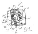
- Fig. 3 illustrates the nested arrangement of lock cylinder 11 and switch insert 40, wherein for better illustration of the lock cylinder 11 is shown without the cover 12.
- Fig. 3 illustrates that the lock cylinder 11 and the switch insert 40 are arranged overlapping each other in the direction of the longitudinal axis of the lock cylinder 11, so that the lock cylinder 11 is immersed in the interior of the switch insert 40, so that the beard 26 is in the region of the switching insert 40.
- the switch insert has a housing which comprises a first housing section for at least one electrical contact bridge and a second housing section for connection terminals.
- the first housing portion is formed substantially disc-shaped, whereas the second housing portion with the Connecting terminals 42 extends on the outer circumference of the first housing portion.
- the lock cylinder 11 immersed into the switch insert 40 so far that the beard 26 is located within the second housing section receiving the connection terminals 42. It is therefore provided in the switching insert a central receiving area for the lock cylinder 11, which is surrounded by the terminals 42 and thus the second housing portion.
- the switching insert 40 has a rotatable actuator 44 which actuates a arranged in the first housing portion (not shown) contact bridge.
- the actuation of the actuator 44 by the beard 26 by means of two drivers 46 (in Fig. 3 only the left driver is visible).
- the two drivers 46 are pin-shaped and integrally connected to the actuator 44. In this way, the beard 26 can be twisted so that it abuts one of the drivers 46 and thereby the actuator 44 is rotated to adjust the provided within the first housing portion contact bridge.
- the lock cylinder 11 has a length of about 40 mm, wherein the depth of the cast housing 10 in the longitudinal direction is only about 48 mm.
Landscapes
- Engineering & Computer Science (AREA)
- Mechanical Engineering (AREA)
- Switch Cases, Indication, And Locking (AREA)
- Push-Button Switches (AREA)
Claims (10)
- Commutateur à clé comprenant un insert de commutateur (40) qui est agencé dans un boîtier en fonderie (10), dont un côté frontal ouvert est fermé par un couvercle (12), et dans lequel un cylindre de serrure (11) doté d'un panneton (26) est fixé sur le couvercle (12),
dans lequel une saillie de verrouillage (24) est réalisée d'une seule pièce avec le boîtier en fonderie (10) en saillie vers l'intérieur de celui-ci, saillie qui, dans la position fermée du cylindre de serrure (11), est engagée par le panneton (26) par l'arrière,
une saillie de montage (30) est réalisée d'une seule pièce avec le boîtier en fonderie (10) en saillie vers l'intérieur de celui-ci, saillie sur laquelle est fixé le couvercle, en particulier vissé,
un côté antérieur (30') de la saillie de montage (30) est réalisé à titre de butée pour le couvercle (12),
une autre butée (28') pour le couvercle (12) est réalisée sur le côté intérieur, opposé à la saillie de montage (30), du boîtier en fonderie (10), et l'autre butée est formée par un côté frontal (28') d'une base en forme de plaque (28) sur laquelle est conformée la saillie de verrouillage (24). - Commutateur à clé selon la revendication 1,
caractérisé en ce que la saillie de verrouillage (24) et la saillie de montage (30) sont réalisées sur des faces intérieures mutuellement opposées du boîtier en fonderie (10). - Commutateur à clé selon la revendication 1,
caractérisé en ce que le couvercle (12) comprend une portion conformée en crochet (36) qui engage la saillie de montage (30) par l'arrière. - Commutateur à clé selon l'une au moins des revendications précédentes,
caractérisé en ce que le couvercle (12) est une pièce de fonderie sur laquelle est conformée une barrette de fixation (14) pour la fixation du cylindre de serrure (11), et la barrette de fixation (14) est réalisée sous la forme d'un logement à section en forme de J. - Commutateur à clé selon la revendication 4,
caractérisé en ce que le cylindre de serrure (11) est fixé sur le logement avec une vis (20), laquelle traverse la branche droite (16) du logement en étant dépourvue de filetage. - Commutateur à clé selon l'une au moins des revendications précédentes,
caractérisé en ce que le cylindre de serrure (11) et l'insert de commutateur (40) sont agencés en chevauchement mutuel en direction de l'axe longitudinal du cylindre de serrure (11), et le panneton (26) plongeant en particulier dans l'insert de commutateur (40). - Commutateur à clé selon l'une des revendications précédentes, caractérisé en ce que l'insert de commutateur (40) comprend un boîtier dans lequel plonge le cylindre de serrure (11).
- Commutateur à clé selon la revendication 7,
caractérisé en ce que le boîtier comprend une première portion de boîtier pour au moins un pont de contact et une seconde portion de boîtier pour des bornes de connexion (42), et le cylindre de serrure (11) plonge dans au moins la seconde portion de boîtier. - Commutateur à clé selon l'une des revendications 6 à 8,
caractérisé en ce que le cylindre de serrure (11) plonge dans une zone de réception centrale du boîtier, et la seconde portion de boîtier délimite la zone de réception au moins partiellement radialement vers l'extérieur. - Commutateur à clé selon l'une des revendications 7 à 9,
caractérisé en ce que l'insert de commutateur (40) comprend un actionneur (44) capable d'être actionné en rotation pour faire commuter le pontet de contact avec au moins un élément d'entraînement (46) qui coopère directement avec le panneton du cylindre de serrure, élément d'entraînement qui ne dépasse pas au-delà du boîtier de l'insert de commutateur (40) en direction longitudinale du cylindre de serrure (11).
Priority Applications (1)
| Application Number | Priority Date | Filing Date | Title |
|---|---|---|---|
| EP07014440.7A EP2019404B1 (fr) | 2007-07-23 | 2007-07-23 | Interrupteur à clé |
Applications Claiming Priority (1)
| Application Number | Priority Date | Filing Date | Title |
|---|---|---|---|
| EP07014440.7A EP2019404B1 (fr) | 2007-07-23 | 2007-07-23 | Interrupteur à clé |
Publications (2)
| Publication Number | Publication Date |
|---|---|
| EP2019404A1 EP2019404A1 (fr) | 2009-01-28 |
| EP2019404B1 true EP2019404B1 (fr) | 2014-04-02 |
Family
ID=38535313
Family Applications (1)
| Application Number | Title | Priority Date | Filing Date |
|---|---|---|---|
| EP07014440.7A Active EP2019404B1 (fr) | 2007-07-23 | 2007-07-23 | Interrupteur à clé |
Country Status (1)
| Country | Link |
|---|---|
| EP (1) | EP2019404B1 (fr) |
Families Citing this family (3)
| Publication number | Priority date | Publication date | Assignee | Title |
|---|---|---|---|---|
| CN104425156A (zh) * | 2013-09-07 | 2015-03-18 | 天津视觉天堂影像文化传媒有限责任公司 | 安全开关锁 |
| CN104425157A (zh) * | 2013-09-09 | 2015-03-18 | 天津视觉天堂影像文化传媒有限责任公司 | 锁具形开关 |
| DE102019100305A1 (de) * | 2019-01-08 | 2020-07-09 | Claus Baumgart | Schlüsselschalter |
Family Cites Families (3)
| Publication number | Priority date | Publication date | Assignee | Title |
|---|---|---|---|---|
| DE1870490U (de) | 1962-12-24 | 1963-04-18 | Gebhard Huegle | Elektrischer schlossschalter. |
| DE19830139B4 (de) * | 1998-07-06 | 2017-01-19 | Geba Elektromechanische und elektronische Schaltgeräte Fabrik GmbH | Schlüsselschaltervorrichtung |
| DE10327267A1 (de) * | 2003-06-17 | 2005-01-20 | Hörmann KG Antriebstechnik | Notentriegelungsvorrichtung |
-
2007
- 2007-07-23 EP EP07014440.7A patent/EP2019404B1/fr active Active
Also Published As
| Publication number | Publication date |
|---|---|
| EP2019404A1 (fr) | 2009-01-28 |
Similar Documents
| Publication | Publication Date | Title |
|---|---|---|
| DE19545196A1 (de) | Drehriegel | |
| EP1856417B1 (fr) | Armature a capacite elevee destinee a connecter deux composants | |
| EP1802831B1 (fr) | Cylindre de fermeture modulaire | |
| EP2019404B1 (fr) | Interrupteur à clé | |
| DE4006707C2 (de) | Vorreiberverschluß | |
| EP2264267B1 (fr) | Serrure | |
| DE8911765U1 (de) | Verschlußgehäuse mit Flansch zur Montage in einem Durchbruch einer dünnwandigen Fläche, insbesondere Blechschranktür oder Blechkastendeckel | |
| DE19726331C2 (de) | Rohrschelle | |
| EP3680927B1 (fr) | Interrupteur à clé | |
| DE102017218709A1 (de) | Einsteckteil für einen Steckplatz in einer teilbaren Kabeldurchführung | |
| DE202016007457U1 (de) | Drehriegelschloss | |
| WO2023232182A1 (fr) | Agencement de barres de verrouillage | |
| EP0428029B1 (fr) | Serrure | |
| DE3134471A1 (de) | "zylinderschloss" | |
| EP0056982A1 (fr) | Came pour loqueteau | |
| DE102008049329A1 (de) | Schlosskastengehäuse für Ganzglastüren | |
| EP2169152B1 (fr) | Clé avec un premier et un second élément | |
| DE102019209382A1 (de) | Gehäuse für einen Antrieb und Antrieb | |
| EP3931417B1 (fr) | Dispositif de verrouillage pour une armoire de commande | |
| DE202005003529U1 (de) | Schließvorrichtungs-Anordnung | |
| EP1263010A1 (fr) | Interrupteur à clef avec commande à câble | |
| EP1577465A1 (fr) | Élément de verrouillage avec fixation pour élément d'actionnement | |
| DE9002502U1 (de) | Vorreiberverschluß | |
| EP4707503A1 (fr) | Dispositif de capuchon de protection, dispositif de blocage, dispositif de blocage de protection contre la poussière et dispositif de fermeture | |
| DE102022113578A1 (de) | Stangenverschluss |
Legal Events
| Date | Code | Title | Description |
|---|---|---|---|
| PUAI | Public reference made under article 153(3) epc to a published international application that has entered the european phase |
Free format text: ORIGINAL CODE: 0009012 |
|
| 17P | Request for examination filed |
Effective date: 20080507 |
|
| AK | Designated contracting states |
Kind code of ref document: A1 Designated state(s): AT BE BG CH CY CZ DE DK EE ES FI FR GB GR HU IE IS IT LI LT LU LV MC MT NL PL PT RO SE SI SK TR |
|
| AX | Request for extension of the european patent |
Extension state: AL BA HR MK RS |
|
| AKX | Designation fees paid |
Designated state(s): CH DE FR GB LI |
|
| 17Q | First examination report despatched |
Effective date: 20100311 |
|
| GRAP | Despatch of communication of intention to grant a patent |
Free format text: ORIGINAL CODE: EPIDOSNIGR1 |
|
| RIC1 | Information provided on ipc code assigned before grant |
Ipc: E05B 17/20 20060101ALN20130606BHEP Ipc: E05B 9/04 20060101ALI20130606BHEP Ipc: H01H 27/06 20060101AFI20130606BHEP |
|
| INTG | Intention to grant announced |
Effective date: 20130625 |
|
| GRAS | Grant fee paid |
Free format text: ORIGINAL CODE: EPIDOSNIGR3 |
|
| GRAA | (expected) grant |
Free format text: ORIGINAL CODE: 0009210 |
|
| AK | Designated contracting states |
Kind code of ref document: B1 Designated state(s): CH DE FR GB LI |
|
| REG | Reference to a national code |
Ref country code: GB Ref legal event code: FG4D Free format text: NOT ENGLISH |
|
| REG | Reference to a national code |
Ref country code: CH Ref legal event code: EP |
|
| REG | Reference to a national code |
Ref country code: CH Ref legal event code: NV Representative=s name: DR. GRAF AND PARTNER AG INTELLECTUAL PROPERTY, CH |
|
| REG | Reference to a national code |
Ref country code: DE Ref legal event code: R096 Ref document number: 502007012921 Country of ref document: DE Effective date: 20140515 |
|
| REG | Reference to a national code |
Ref country code: DE Ref legal event code: R097 Ref document number: 502007012921 Country of ref document: DE |
|
| PLBE | No opposition filed within time limit |
Free format text: ORIGINAL CODE: 0009261 |
|
| STAA | Information on the status of an ep patent application or granted ep patent |
Free format text: STATUS: NO OPPOSITION FILED WITHIN TIME LIMIT |
|
| 26N | No opposition filed |
Effective date: 20150106 |
|
| REG | Reference to a national code |
Ref country code: DE Ref legal event code: R097 Ref document number: 502007012921 Country of ref document: DE Effective date: 20150106 |
|
| REG | Reference to a national code |
Ref country code: FR Ref legal event code: PLFP Year of fee payment: 10 |
|
| REG | Reference to a national code |
Ref country code: FR Ref legal event code: PLFP Year of fee payment: 11 |
|
| REG | Reference to a national code |
Ref country code: FR Ref legal event code: PLFP Year of fee payment: 12 |
|
| PGFP | Annual fee paid to national office [announced via postgrant information from national office to epo] |
Ref country code: GB Payment date: 20250722 Year of fee payment: 19 |
|
| PGFP | Annual fee paid to national office [announced via postgrant information from national office to epo] |
Ref country code: FR Payment date: 20250724 Year of fee payment: 19 |
|
| PGFP | Annual fee paid to national office [announced via postgrant information from national office to epo] |
Ref country code: CH Payment date: 20250801 Year of fee payment: 19 |
|
| PGFP | Annual fee paid to national office [announced via postgrant information from national office to epo] |
Ref country code: DE Payment date: 20250926 Year of fee payment: 19 |