EP2020175A1 - Moissonneuse dotée d'un dispositif de transbordement réglable - Google Patents
Moissonneuse dotée d'un dispositif de transbordement réglable Download PDFInfo
- Publication number
- EP2020175A1 EP2020175A1 EP08012749A EP08012749A EP2020175A1 EP 2020175 A1 EP2020175 A1 EP 2020175A1 EP 08012749 A EP08012749 A EP 08012749A EP 08012749 A EP08012749 A EP 08012749A EP 2020175 A1 EP2020175 A1 EP 2020175A1
- Authority
- EP
- European Patent Office
- Prior art keywords
- harvesting machine
- machine according
- shaft
- ejection opening
- section
- Prior art date
- Legal status (The legal status is an assumption and is not a legal conclusion. Google has not performed a legal analysis and makes no representation as to the accuracy of the status listed.)
- Granted
Links
- 238000003306 harvesting Methods 0.000 title claims description 31
- 239000004459 forage Substances 0.000 claims abstract description 18
- 241001124569 Lycaenidae Species 0.000 description 3
- 241000209149 Zea Species 0.000 description 2
- 235000005824 Zea mays ssp. parviglumis Nutrition 0.000 description 2
- 235000002017 Zea mays subsp mays Nutrition 0.000 description 2
- 235000005822 corn Nutrition 0.000 description 2
- 230000001133 acceleration Effects 0.000 description 1
- 230000015572 biosynthetic process Effects 0.000 description 1
- 239000012141 concentrate Substances 0.000 description 1
- 239000000446 fuel Substances 0.000 description 1
- 239000000463 material Substances 0.000 description 1
- 230000000630 rising effect Effects 0.000 description 1
- 230000007704 transition Effects 0.000 description 1
Images


Classifications
-
- A—HUMAN NECESSITIES
- A01—AGRICULTURE; FORESTRY; ANIMAL HUSBANDRY; HUNTING; TRAPPING; FISHING
- A01D—HARVESTING; MOWING
- A01D43/00—Mowers combined with apparatus performing additional operations while mowing
- A01D43/08—Mowers combined with apparatus performing additional operations while mowing with means for cutting up the mown crop, e.g. forage harvesters
- A01D43/086—Mowers combined with apparatus performing additional operations while mowing with means for cutting up the mown crop, e.g. forage harvesters and means for collecting, gathering or loading mown material
- A01D43/087—Mowers combined with apparatus performing additional operations while mowing with means for cutting up the mown crop, e.g. forage harvesters and means for collecting, gathering or loading mown material with controllable discharge spout
Definitions
- the present invention relates to a self-propelled harvester with a transfer device for transferring crop from the harvester to a transport vehicle adjacent to the harvester.
- a transfer device for transferring crop from the harvester to a transport vehicle adjacent to the harvester.
- Such an unloading device generally comprises a so-called discharge chute, a discharge channel which can be placed bridging over the side wall of a transport vehicle in order to load the crop into an upwardly open cargo space of the transport vehicle.
- DE 32 24 269 A1 proposes a harvester with an ejection manifold which is divided into two pivotally interconnected sections. In a working position of the discharge chute, the two sections form a continuous line and touch approximately at the level of the roof of a cab of the harvester. The upper portion of the discharge chute may be swung downwardly to reduce the height of the harvester to a roadworthy value, thereby breaking the line. Even in the downwardly pivoted position, the chute obstructs the view from the cab.
- a harvesting machine having an ejection elbow which is extensible at its free end by a displaceable element in a substantially horizontal direction.
- the sliding element allows the uniform Loading a support vehicle with crop even if the harvester is equipped with a far to the side unloading harvest header, in particular a corn header, which prevents the escort vehicle to drive close to the harvester. Since the free end of the discharge elbow extends substantially horizontally, no appreciable change in height of the discharge elbow is associated with the extension or retraction of the displaceable element.
- the object of the present invention is to provide a harvesting machine capable of loading high-level escort vehicles without impairing the roadworthiness of the discharge chute.
- the object is achieved in that in a harvesting machine with a machine housing and an ejection opening of the machine housing movably mounted discharge elbow, the ejection opening is height-adjustable to the machine housing.
- the ejection opening is height-adjustable to the machine housing.
- the ejection opening is preferably an upper end of a first shaft section of a shaft, which is telescopic at least two, preferably exactly two Having mutually displaceable shaft sections.
- the manhole sections may be of constant cross-section to provide continuous guidance for crops to be ejected both in a raised and lowered position and possibly also in intermediate positions.
- At least the second shaft section diverges downward, and the first shaft section having the ejection opening engages in the second shaft section.
- the divergent shape facilitates the formation of a streamlined transition to a processing chamber of the harvesting machine, such as a chopper drum, which extends over a substantial portion of the width of the machine housing.
- a consequence of the divergent shape is that there is a gap in the lowered position between the well sections.
- the divergent shape of the second manhole section or of the whole manhole makes it possible to receive a high-width crop stream at an inlet at the lower end of the manhole.
- an inlet width at the lower end of the shaft can be over 700 mm.
- the shaft processing tools such as a header, a Preceding chopper drum or cracker rolls large width that allow a quick and economical harvesting.
- the walls of the second shaft section diverge downward at an angle of at most 20 °, preferably 10 ° to 18 °, to the shaft axis. Smaller angles make for a given inlet width at the bottom of the shaft, an inordinately large height of the shaft required; larger angles have the problem that crops can deposit on the inner surface of the manhole section
- post accelerators for accelerating the crop to the longitudinal mid-plane and upwards may be arranged on a foot portion of a lower one of the manhole sections on both sides of a longitudinal center plane to provide efficient conveyance of the crop.
- Nachbeschreiber can also be provided on a downwardly diverging shaft, but their task there is essentially only the acceleration of the crop in the shaft longitudinal direction, since the merging is achieved to the longitudinal center plane substantially by the shape of the shaft.
- the first manhole section is slidable upward and away from a cab of the harvester.
- the ejection opening is close to the driver's cab and the spur for driving on the road with little projection on the machine housing can be placed in the raised position, the distance of the discharge chute to the driver's cab and thus the range of the discharge elbow is increased.
- the spout is also rotatable about a vertical axis with the spout opening as the center.
- the cab obstructs rotation of the discharge chute the less the higher the discharge opening.
- the freedom of rotation of the discharge chute usually only slightly beyond 180 °, it is possible with the invention easily, a freedom of rotation of the chute of 210 ° or more, even better of at least 240 ° or even an unlimited freedom of rotation of the discharge chute to realize.
- the achievable rotational freedom is greater, the higher the ejection opening is on the harvester.
- the freedom of rotation is unlimited.
- a vehicle to be loaded does not necessarily have to travel in a conventional manner next to the harvesting vehicle or behind it, but it may also have a projection relative to the harvesting vehicle. Since the driver of the harvester can see the transport vehicle well while driving without having to look around, the harvesting operation is simplified.
- the latter is preferably pivotable about a horizontal axis adjacent the spout opening from its raised working position to a lowered travel position.
- the invention is applicable to any harvesters that transfer collected crop to a support vehicle using a chute.
- a preferred field of application of the invention are forage harvesters, since in these crops are generally issued during the harvesting process continuously over the chute.
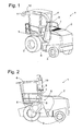
- Fig. 1 shows a field harvester 1 according to the invention in a perspective view obliquely from behind.
- a machine housing 2 of the forage harvester 1 includes a motor for driving the wheels 3, internal units of the machine housing 2 such as a chopper drum and / or cracker rollers and a not shown in the figure, mounted on a front of the forage harvester 1 header.
- Harvested from the ground with the help of the harvest header crop is crushed in a not visible in the figure, inside the machine housing 2 below a cab 4 arranged chopping drum, grains contained in the crop, especially corn, are crushed by the cutterhead cracker rollers, and finally that Crop output in a rising behind the cab 4 chute 5.
- Fig. 1 shows a field harvester 1 according to the invention in a perspective view obliquely from behind.
- a machine housing 2 of the forage harvester 1 includes a motor for driving the wheels 3, internal units of the machine housing 2 such as a chopper drum and / or cracker rollers and
- a Nachbelixer 6 is arranged at a lower end of the discharge chute 5. This comprises in a chamber, a rotor with a plurality of rotating blades, on the one hand, the crushed Driving crop by direct contact in the chute 5 upwards and on the other hand form a radial fan whose air flow drives the crop over the entire length of the discharge chute and beyond.
- the discharge chute is composed of two telescopically intermeshing shaft sections 7, 8. At a turntable 9 forming the upper end of the shaft section 7, an ejection elbow 10 is rotatably mounted about a vertical axis of the turntable 9.
- the Figures 1 and 2 show the chute 10 in an orientation that allows the over-loading of crop in a next to the forage harvester 1 driving, not shown transport vehicle.
- An adjustable discharge flap 11 at the free end of the discharge chute 10 is directed steeply downwards, so that the crop is dropped almost vertically down into the transport vehicle.
- Fig. 3 shows a section through the discharge chute 5 along the line III-III of Fig. 2 , While, as in Fig. 2 shown, the dimension of the discharge chute 5 across the cutting plane III-III is substantially constant over the entire height of the discharge chute 5, takes in the plane of the Fig. 3 the width of the discharge chute 5 from the circular turntable 9 down continuously to.
- This shape of the discharge chute 5 facilitates the transfer of the chopped crop from the chopper drum extending over a majority of the width of the machine housing 2 into the discharge chute 5.
- the chopper drum may have a width of 800 or even 1000 mm and above; any subsequent cracker rollers are each slightly narrower than the cutterhead to concentrate the crop flow, and an inlet at the bottom of the tray section 8 is again somewhat narrower than the cracker rollers.
- Fig. 3 shows with solid lines the upper manhole section 7 in a maximum raised position. In this position, a lower edge of the shaft section 7 lies completely on the inside at an upper edge of the lower shaft section 8.
- the shaft sections 7, 8 and the adjoining spout 10 form a continuous line for the crop from which this, driven by the air flow of the Nachbevanters 6, out of the cutterhead into the cargo compartment of the transport vehicle.
- the walls of the shaft sections 7, 8 span with the dash-dotted line longitudinal axis of the shaft at an angle ⁇ of 14 °.
- the discharge chute 10 is connected to the turntable 9 via a hinge 13 with a horizontal axis. If, as in Fig. 4 and 5 shown, the shaft section 7 is in the lowered position, in which the turntable 9 is substantially flush with the surface of the machine housing 2, can be additionally lowered by pivoting in the hinge 13 of the spout 10, so that he just above the machine housing. 2 extends.
- the discharge chute 5 is not exactly vertical but relative to the vehicle longitudinal direction oriented towards the back. This has the consequence that in the raised position of the Figures 1 and 2 the turntable 9 is spaced from the rear wall of the cab 4. The greater this distance, the less the rotational freedom of the discharge chute 10 is limited by the vertical axis of the turntable 9 through the cab 4.
- the shaft sections 7, 8 can be so long that in a raised position, when the turntable 9 is above the roof of the car 4 or just below, the discharge chute 10 has a freedom of rotation of 360 °. In the lowered position, however, in particular in Fig. 5 can be seen, the turntable 9 is moved directly to the rear wall of the cab 4, so as to minimize the projection of the free end 11 of the discharge chute 10 to the rear beyond the machine housing 2 addition.
- Fig. 6 shows a section similar to that of Fig. 3 through the discharge chute of a forage harvester according to a second embodiment of the invention.
- a foot section 14 of the discharge chute 5 ' which is substantially wider than the manhole sections 7', 8 ', both sides of a longitudinal mid-plane of the forage harvester 1 shown as a dot-dash line are two post-accelerators 15 with the order of transversal to the cutting plane Fig.
- the inlet opening 17 is not substantially narrower than the chopper drum 18 and substantially wider than the chute 5 '.
- the rotation of the post-accelerator 15 rotating behind the inlet opening 17 the crop is conveyed to the center of the foot section 14 and driven from there into the discharge chute 5 '.
- the discharge chute 5 'always works the same regardless of how far the shaft sections 7', 8 'overlap or are pulled apart.
- the Matterlade wasted the forage harvester 1 can be exactly adapted to the loading edge height of the transport vehicle. The crop does not have to be lifted higher than absolutely necessary for overcrowding.
- the post-accelerators 15 By consequently operating the post-accelerators 15 with power adapted to the transfer height, fuel can be saved.
Landscapes
- Life Sciences & Earth Sciences (AREA)
- Environmental Sciences (AREA)
- Harvester Elements (AREA)
- Threshing Machine Elements (AREA)
- Harvesting Machines For Specific Crops (AREA)
Applications Claiming Priority (1)
| Application Number | Priority Date | Filing Date | Title |
|---|---|---|---|
| DE102007036799A DE102007036799A1 (de) | 2007-08-03 | 2007-08-03 | Erntemaschine mit verstellbarer Überladeeinrichtung |
Publications (2)
| Publication Number | Publication Date |
|---|---|
| EP2020175A1 true EP2020175A1 (fr) | 2009-02-04 |
| EP2020175B1 EP2020175B1 (fr) | 2014-09-10 |
Family
ID=39926558
Family Applications (1)
| Application Number | Title | Priority Date | Filing Date |
|---|---|---|---|
| EP08012749.1A Not-in-force EP2020175B1 (fr) | 2007-08-03 | 2008-07-15 | Moissonneuse dotée d'un dispositif de transbordement réglable |
Country Status (4)
| Country | Link |
|---|---|
| US (1) | US8438821B2 (fr) |
| EP (1) | EP2020175B1 (fr) |
| DE (1) | DE102007036799A1 (fr) |
| RU (1) | RU2463767C2 (fr) |
Families Citing this family (8)
| Publication number | Priority date | Publication date | Assignee | Title |
|---|---|---|---|---|
| USD619627S1 (en) * | 2009-05-29 | 2010-07-13 | Claas Kgaa Mbh | Harvester spout |
| US20110011046A1 (en) * | 2009-07-14 | 2011-01-20 | Byard Robert B | Discharge diverter for lawnmower and similar lawn care apparatus |
| US8528845B2 (en) * | 2010-05-07 | 2013-09-10 | Anders Ragnarsson | Flexible chipper chute having two chip discharge configurations |
| USD667850S1 (en) * | 2012-02-13 | 2012-09-25 | J. & M. Manufacturing Co., Inc. | Grain auger housing having an askewed discharge outlet attachment |
| JP6296355B2 (ja) * | 2014-10-28 | 2018-03-20 | 井関農機株式会社 | コンバイン |
| AR116122A1 (es) * | 2018-10-02 | 2021-04-07 | Accorroni Rivas Bruno | Máquina picadora de biomasa de caña de azúcar incorporada sobre una cosechadora |
| CN112715149A (zh) * | 2021-01-15 | 2021-04-30 | 陈业才 | 整秆式或切段式一行或二行同时收割的甘蔗联合收割机 |
| EP4399958B1 (fr) * | 2023-01-12 | 2025-10-29 | CLAAS Saulgau GmbH | Ramasseuse-hacheuse dotée d'un coude d'éjection |
Citations (10)
| Publication number | Priority date | Publication date | Assignee | Title |
|---|---|---|---|---|
| US1336065A (en) | 1915-09-24 | 1920-04-06 | Nicholas M Bowers | Hay-loader |
| US2778510A (en) * | 1952-10-14 | 1957-01-22 | Cobey Corp | Swivel discharge stack for agricultural harvester |
| US3464471A (en) * | 1967-07-06 | 1969-09-02 | Case Co J I | Blower spout mechanism |
| US4148274A (en) | 1974-10-15 | 1979-04-10 | Agfa-Gevaert N.V. | Processing apparatus |
| US4184274A (en) * | 1977-08-31 | 1980-01-22 | Vohl Paul Eugene | Ejection tube assembly for a snowblower |
| DE3224269A1 (de) * | 1981-07-07 | 1983-03-17 | Alois Pöttinger Landmaschinen-Gesellschaft m.b.H., 8900 Augsburg | Auswurfkruemmer fuer landwirtschaftliche maschinen |
| EP0492195A1 (fr) * | 1990-12-13 | 1992-07-01 | Claas Ohg | Faucheuse-hacheuse |
| DE10211706A1 (de) | 2002-03-16 | 2003-09-25 | Deere & Co | Austrageinrichtung einer landwirtschaftlichen Erntemaschine |
| US20040116169A1 (en) * | 2002-08-28 | 2004-06-17 | Heinrich Isfort | Device for controlling a forager chute |
| DE10335583A1 (de) * | 2003-07-31 | 2005-03-10 | Claas Selbstfahr Erntemasch | Ladeeinrichtung für landwirtschaftliche Erntemaschine |
Family Cites Families (18)
| Publication number | Priority date | Publication date | Assignee | Title |
|---|---|---|---|---|
| US708082A (en) * | 1902-03-17 | 1902-09-02 | Frank L Sackett | Chute. |
| US1618531A (en) * | 1926-05-10 | 1927-02-22 | Francis H Hampton | Funnel |
| US2253794A (en) * | 1940-03-22 | 1941-08-26 | Raymond H Lindholm | Ensilage cutter attachment for tractors |
| US2634570A (en) * | 1949-05-06 | 1953-04-14 | Idaho Egg Producers | Horizontal topper and loader |
| US3070940A (en) * | 1958-07-17 | 1963-01-01 | Patent Concern Nv | Forage harvesters |
| US3911650A (en) * | 1974-01-02 | 1975-10-14 | Donald F Johnson | Hay loading apparatus |
| US4821495A (en) * | 1987-03-23 | 1989-04-18 | Deere & Company | Blower and discharge spout assembly |
| SU1584805A1 (ru) * | 1988-09-20 | 1990-08-15 | Производственное объединение "Херсонский комбайновый завод им.Г.И.Петровского" | Выгрузной силосопровод |
| US4996831A (en) * | 1990-05-07 | 1991-03-05 | Deere & Company | Cotton basket extension latch |
| SU1752255A1 (ru) * | 1990-12-29 | 1992-08-07 | Головное Специализированное Конструкторское Бюро По Комплексу Кормоуборочных Машин Производственного Объединения "Гомсельмаш" | Выгрузной трубопровод сельскохоз йственной уборочной машины |
| US5857908A (en) * | 1996-12-18 | 1999-01-12 | Case Corporation | Duct structure for a cotton harvester |
| DE29700426U1 (de) * | 1997-01-11 | 1997-05-15 | Claas KGaA, 33428 Harsewinkel | Selbstfahrender Feldhäcksler mit am Ende seines Auswurfrohres angeordneter verschwenkbarer Klappe |
| DE10021657C2 (de) * | 2000-05-04 | 2002-08-01 | Krone Bernhard Gmbh Maschf | Erntemaschine, insbesondere selbstfahrender Feldhäcksler |
| RU2258350C2 (ru) * | 2001-12-28 | 2005-08-20 | Чинов Александр Константинович | Выгрузной трубопровод кормоуборочного комбайна |
| DE10228880B4 (de) * | 2002-06-27 | 2005-09-08 | Jakob Voets Ing. Grad. Gmbh & Co. Kg Rheinische Landschaftspflege | Mähgerät zur Rasen- und Landschaftswiesenpflege mit einer Vorrichtung zur Aufnahme und Zerkleinerung von Mähgut |
| SE526228C2 (sv) * | 2003-10-30 | 2005-08-02 | Sandvik Intellectual Property | Bulklastanordning |
| US7117817B2 (en) * | 2004-08-03 | 2006-10-10 | Troy Overstreet | Animal feed harvesting and dispensing system |
| US7204752B2 (en) * | 2005-09-19 | 2007-04-17 | Cnh America Llc | Automatically deployable and storable cover apparatus for directing cotton flow from a conveyor duct of a cotton harvester to a cotton receiver thereof |
-
2007
- 2007-08-03 DE DE102007036799A patent/DE102007036799A1/de not_active Withdrawn
-
2008
- 2008-07-15 EP EP08012749.1A patent/EP2020175B1/fr not_active Not-in-force
- 2008-07-31 RU RU2008131474/13A patent/RU2463767C2/ru active
- 2008-08-04 US US12/185,784 patent/US8438821B2/en not_active Expired - Fee Related
Patent Citations (10)
| Publication number | Priority date | Publication date | Assignee | Title |
|---|---|---|---|---|
| US1336065A (en) | 1915-09-24 | 1920-04-06 | Nicholas M Bowers | Hay-loader |
| US2778510A (en) * | 1952-10-14 | 1957-01-22 | Cobey Corp | Swivel discharge stack for agricultural harvester |
| US3464471A (en) * | 1967-07-06 | 1969-09-02 | Case Co J I | Blower spout mechanism |
| US4148274A (en) | 1974-10-15 | 1979-04-10 | Agfa-Gevaert N.V. | Processing apparatus |
| US4184274A (en) * | 1977-08-31 | 1980-01-22 | Vohl Paul Eugene | Ejection tube assembly for a snowblower |
| DE3224269A1 (de) * | 1981-07-07 | 1983-03-17 | Alois Pöttinger Landmaschinen-Gesellschaft m.b.H., 8900 Augsburg | Auswurfkruemmer fuer landwirtschaftliche maschinen |
| EP0492195A1 (fr) * | 1990-12-13 | 1992-07-01 | Claas Ohg | Faucheuse-hacheuse |
| DE10211706A1 (de) | 2002-03-16 | 2003-09-25 | Deere & Co | Austrageinrichtung einer landwirtschaftlichen Erntemaschine |
| US20040116169A1 (en) * | 2002-08-28 | 2004-06-17 | Heinrich Isfort | Device for controlling a forager chute |
| DE10335583A1 (de) * | 2003-07-31 | 2005-03-10 | Claas Selbstfahr Erntemasch | Ladeeinrichtung für landwirtschaftliche Erntemaschine |
Also Published As
| Publication number | Publication date |
|---|---|
| EP2020175B1 (fr) | 2014-09-10 |
| RU2463767C2 (ru) | 2012-10-20 |
| DE102007036799A1 (de) | 2009-02-05 |
| US20090113866A1 (en) | 2009-05-07 |
| US8438821B2 (en) | 2013-05-14 |
| RU2008131474A (ru) | 2010-02-10 |
Similar Documents
| Publication | Publication Date | Title |
|---|---|---|
| EP2020175B1 (fr) | Moissonneuse dotée d'un dispositif de transbordement réglable | |
| EP1145619B1 (fr) | Machine de récolte pour travail sur pente | |
| EP1393613B1 (fr) | Dispositif de contrôle pour une goulotte de transfert | |
| DE60127193T2 (de) | Korntank einer Erntemaschine | |
| EP1074175B1 (fr) | Distributeur pour le résidu des produits de récolte éjecté d'une moissonneuse-batteuse | |
| EP0580026B1 (fr) | Faucheuse avec boîtier et avec canal arrière d'expectoration ayant un dispositif de guidage | |
| EP1344446A1 (fr) | Dispositif de décharge d'une récolteuse agricole | |
| EP0787425B1 (fr) | Hacheuse et dispositif convoyeur | |
| EP0044505B1 (fr) | Récolteuse pourvue d'un dispositif convoyeur de la récolte | |
| EP3078256B1 (fr) | Chariot de recolte comprenant un appareil de dosage et d'epandage | |
| EP1068791A1 (fr) | Faucheuse automotrice munie de convoyeurs | |
| DE19832787B4 (de) | Selbstfahrender Kompostumsetzer | |
| EP1330951B1 (fr) | Appareil mélangeur de fourrage | |
| AT513427B1 (de) | Erntewagen zum Aufnehmen und Transport von Pflanzen oder Pflanzenteilen | |
| EP1588601B1 (fr) | Machine de récolte avec un dispositif de décharge | |
| EP1514470A1 (fr) | Véhicule de distribution de fourrages | |
| DE1942733A1 (de) | Erntemaschine | |
| DE69021061T2 (de) | Entleerungsvorrichtung für den Sammelbehälter eines Mähdreschers. | |
| EP3069596B1 (fr) | Ensileuse | |
| EP0540130A2 (fr) | Dispositif de mélange et de dosage de fourrage pour bétail ou similaire | |
| EP1264527B1 (fr) | Groupement de fixation d'un arrangement pour traiter et convoyer des grains | |
| EP0260334B1 (fr) | Dispositif de vidage | |
| DE68904501T2 (de) | Maschine zum versetzen von auf dem boden liegendem pflanzengut. | |
| DE1086082B (de) | Heu- und Gruenfutterlader mit Zerkleinerungs- und Abwurfvorrichtung | |
| EP4223402A1 (fr) | Mélangeur de fourrage avec vis de mélange améliorée |
Legal Events
| Date | Code | Title | Description |
|---|---|---|---|
| PUAI | Public reference made under article 153(3) epc to a published international application that has entered the european phase |
Free format text: ORIGINAL CODE: 0009012 |
|
| 17P | Request for examination filed |
Effective date: 20080804 |
|
| AK | Designated contracting states |
Kind code of ref document: A1 Designated state(s): AT BE BG CH CY CZ DE DK EE ES FI FR GB GR HR HU IE IS IT LI LT LU LV MC MT NL NO PL PT RO SE SI SK TR |
|
| AX | Request for extension of the european patent |
Extension state: AL BA MK RS |
|
| 17Q | First examination report despatched |
Effective date: 20090804 |
|
| AKX | Designation fees paid |
Designated state(s): AT BE BG CH CY CZ DE DK EE ES FI FR GB GR HR HU IE IS IT LI LT LU LV MC MT NL NO PL PT RO SE SI SK TR |
|
| GRAP | Despatch of communication of intention to grant a patent |
Free format text: ORIGINAL CODE: EPIDOSNIGR1 |
|
| INTG | Intention to grant announced |
Effective date: 20140120 |
|
| GRAS | Grant fee paid |
Free format text: ORIGINAL CODE: EPIDOSNIGR3 |
|
| GRAA | (expected) grant |
Free format text: ORIGINAL CODE: 0009210 |
|
| AK | Designated contracting states |
Kind code of ref document: B1 Designated state(s): AT BE BG CH CY CZ DE DK EE ES FI FR GB GR HR HU IE IS IT LI LT LU LV MC MT NL NO PL PT RO SE SI SK TR |
|
| REG | Reference to a national code |
Ref country code: GB Ref legal event code: FG4D Free format text: NOT ENGLISH |
|
| REG | Reference to a national code |
Ref country code: CH Ref legal event code: EP |
|
| REG | Reference to a national code |
Ref country code: IE Ref legal event code: FG4D Free format text: LANGUAGE OF EP DOCUMENT: GERMAN |
|
| REG | Reference to a national code |
Ref country code: AT Ref legal event code: REF Ref document number: 686184 Country of ref document: AT Kind code of ref document: T Effective date: 20141015 |
|
| REG | Reference to a national code |
Ref country code: DE Ref legal event code: R096 Ref document number: 502008012183 Country of ref document: DE Effective date: 20141023 |
|
| PG25 | Lapsed in a contracting state [announced via postgrant information from national office to epo] |
Ref country code: NO Free format text: LAPSE BECAUSE OF FAILURE TO SUBMIT A TRANSLATION OF THE DESCRIPTION OR TO PAY THE FEE WITHIN THE PRESCRIBED TIME-LIMIT Effective date: 20141210 Ref country code: GR Free format text: LAPSE BECAUSE OF FAILURE TO SUBMIT A TRANSLATION OF THE DESCRIPTION OR TO PAY THE FEE WITHIN THE PRESCRIBED TIME-LIMIT Effective date: 20141211 Ref country code: LT Free format text: LAPSE BECAUSE OF FAILURE TO SUBMIT A TRANSLATION OF THE DESCRIPTION OR TO PAY THE FEE WITHIN THE PRESCRIBED TIME-LIMIT Effective date: 20140910 Ref country code: FI Free format text: LAPSE BECAUSE OF FAILURE TO SUBMIT A TRANSLATION OF THE DESCRIPTION OR TO PAY THE FEE WITHIN THE PRESCRIBED TIME-LIMIT Effective date: 20140910 Ref country code: SE Free format text: LAPSE BECAUSE OF FAILURE TO SUBMIT A TRANSLATION OF THE DESCRIPTION OR TO PAY THE FEE WITHIN THE PRESCRIBED TIME-LIMIT Effective date: 20140910 Ref country code: ES Free format text: LAPSE BECAUSE OF FAILURE TO SUBMIT A TRANSLATION OF THE DESCRIPTION OR TO PAY THE FEE WITHIN THE PRESCRIBED TIME-LIMIT Effective date: 20140910 |
|
| REG | Reference to a national code |
Ref country code: NL Ref legal event code: VDEP Effective date: 20140910 |
|
| REG | Reference to a national code |
Ref country code: LT Ref legal event code: MG4D |
|
| PG25 | Lapsed in a contracting state [announced via postgrant information from national office to epo] |
Ref country code: LV Free format text: LAPSE BECAUSE OF FAILURE TO SUBMIT A TRANSLATION OF THE DESCRIPTION OR TO PAY THE FEE WITHIN THE PRESCRIBED TIME-LIMIT Effective date: 20140910 Ref country code: HR Free format text: LAPSE BECAUSE OF FAILURE TO SUBMIT A TRANSLATION OF THE DESCRIPTION OR TO PAY THE FEE WITHIN THE PRESCRIBED TIME-LIMIT Effective date: 20140910 Ref country code: CY Free format text: LAPSE BECAUSE OF FAILURE TO SUBMIT A TRANSLATION OF THE DESCRIPTION OR TO PAY THE FEE WITHIN THE PRESCRIBED TIME-LIMIT Effective date: 20140910 |
|
| PG25 | Lapsed in a contracting state [announced via postgrant information from national office to epo] |
Ref country code: NL Free format text: LAPSE BECAUSE OF FAILURE TO SUBMIT A TRANSLATION OF THE DESCRIPTION OR TO PAY THE FEE WITHIN THE PRESCRIBED TIME-LIMIT Effective date: 20140910 |
|
| PG25 | Lapsed in a contracting state [announced via postgrant information from national office to epo] |
Ref country code: SK Free format text: LAPSE BECAUSE OF FAILURE TO SUBMIT A TRANSLATION OF THE DESCRIPTION OR TO PAY THE FEE WITHIN THE PRESCRIBED TIME-LIMIT Effective date: 20140910 Ref country code: EE Free format text: LAPSE BECAUSE OF FAILURE TO SUBMIT A TRANSLATION OF THE DESCRIPTION OR TO PAY THE FEE WITHIN THE PRESCRIBED TIME-LIMIT Effective date: 20140910 Ref country code: RO Free format text: LAPSE BECAUSE OF FAILURE TO SUBMIT A TRANSLATION OF THE DESCRIPTION OR TO PAY THE FEE WITHIN THE PRESCRIBED TIME-LIMIT Effective date: 20140910 Ref country code: PT Free format text: LAPSE BECAUSE OF FAILURE TO SUBMIT A TRANSLATION OF THE DESCRIPTION OR TO PAY THE FEE WITHIN THE PRESCRIBED TIME-LIMIT Effective date: 20150112 Ref country code: CZ Free format text: LAPSE BECAUSE OF FAILURE TO SUBMIT A TRANSLATION OF THE DESCRIPTION OR TO PAY THE FEE WITHIN THE PRESCRIBED TIME-LIMIT Effective date: 20140910 Ref country code: IS Free format text: LAPSE BECAUSE OF FAILURE TO SUBMIT A TRANSLATION OF THE DESCRIPTION OR TO PAY THE FEE WITHIN THE PRESCRIBED TIME-LIMIT Effective date: 20150110 |
|
| PG25 | Lapsed in a contracting state [announced via postgrant information from national office to epo] |
Ref country code: PL Free format text: LAPSE BECAUSE OF FAILURE TO SUBMIT A TRANSLATION OF THE DESCRIPTION OR TO PAY THE FEE WITHIN THE PRESCRIBED TIME-LIMIT Effective date: 20140910 |
|
| REG | Reference to a national code |
Ref country code: DE Ref legal event code: R097 Ref document number: 502008012183 Country of ref document: DE |
|
| PLBE | No opposition filed within time limit |
Free format text: ORIGINAL CODE: 0009261 |
|
| STAA | Information on the status of an ep patent application or granted ep patent |
Free format text: STATUS: NO OPPOSITION FILED WITHIN TIME LIMIT |
|
| PG25 | Lapsed in a contracting state [announced via postgrant information from national office to epo] |
Ref country code: DK Free format text: LAPSE BECAUSE OF FAILURE TO SUBMIT A TRANSLATION OF THE DESCRIPTION OR TO PAY THE FEE WITHIN THE PRESCRIBED TIME-LIMIT Effective date: 20140910 |
|
| 26N | No opposition filed |
Effective date: 20150611 |
|
| PG25 | Lapsed in a contracting state [announced via postgrant information from national office to epo] |
Ref country code: IT Free format text: LAPSE BECAUSE OF FAILURE TO SUBMIT A TRANSLATION OF THE DESCRIPTION OR TO PAY THE FEE WITHIN THE PRESCRIBED TIME-LIMIT Effective date: 20140910 |
|
| PG25 | Lapsed in a contracting state [announced via postgrant information from national office to epo] |
Ref country code: SI Free format text: LAPSE BECAUSE OF FAILURE TO SUBMIT A TRANSLATION OF THE DESCRIPTION OR TO PAY THE FEE WITHIN THE PRESCRIBED TIME-LIMIT Effective date: 20140910 |
|
| PG25 | Lapsed in a contracting state [announced via postgrant information from national office to epo] |
Ref country code: MC Free format text: LAPSE BECAUSE OF FAILURE TO SUBMIT A TRANSLATION OF THE DESCRIPTION OR TO PAY THE FEE WITHIN THE PRESCRIBED TIME-LIMIT Effective date: 20140910 |
|
| REG | Reference to a national code |
Ref country code: CH Ref legal event code: PL |
|
| GBPC | Gb: european patent ceased through non-payment of renewal fee |
Effective date: 20150715 |
|
| PG25 | Lapsed in a contracting state [announced via postgrant information from national office to epo] |
Ref country code: LU Free format text: LAPSE BECAUSE OF FAILURE TO SUBMIT A TRANSLATION OF THE DESCRIPTION OR TO PAY THE FEE WITHIN THE PRESCRIBED TIME-LIMIT Effective date: 20150715 |
|
| REG | Reference to a national code |
Ref country code: IE Ref legal event code: MM4A |
|
| PG25 | Lapsed in a contracting state [announced via postgrant information from national office to epo] |
Ref country code: LI Free format text: LAPSE BECAUSE OF NON-PAYMENT OF DUE FEES Effective date: 20150731 Ref country code: CH Free format text: LAPSE BECAUSE OF NON-PAYMENT OF DUE FEES Effective date: 20150731 Ref country code: GB Free format text: LAPSE BECAUSE OF NON-PAYMENT OF DUE FEES Effective date: 20150715 |
|
| REG | Reference to a national code |
Ref country code: FR Ref legal event code: ST Effective date: 20160331 |
|
| PG25 | Lapsed in a contracting state [announced via postgrant information from national office to epo] |
Ref country code: FR Free format text: LAPSE BECAUSE OF NON-PAYMENT OF DUE FEES Effective date: 20150731 |
|
| PG25 | Lapsed in a contracting state [announced via postgrant information from national office to epo] |
Ref country code: IE Free format text: LAPSE BECAUSE OF NON-PAYMENT OF DUE FEES Effective date: 20150715 |
|
| REG | Reference to a national code |
Ref country code: AT Ref legal event code: MM01 Ref document number: 686184 Country of ref document: AT Kind code of ref document: T Effective date: 20150715 |
|
| PG25 | Lapsed in a contracting state [announced via postgrant information from national office to epo] |
Ref country code: AT Free format text: LAPSE BECAUSE OF NON-PAYMENT OF DUE FEES Effective date: 20150715 |
|
| PG25 | Lapsed in a contracting state [announced via postgrant information from national office to epo] |
Ref country code: MT Free format text: LAPSE BECAUSE OF FAILURE TO SUBMIT A TRANSLATION OF THE DESCRIPTION OR TO PAY THE FEE WITHIN THE PRESCRIBED TIME-LIMIT Effective date: 20140910 |
|
| PG25 | Lapsed in a contracting state [announced via postgrant information from national office to epo] |
Ref country code: HU Free format text: LAPSE BECAUSE OF FAILURE TO SUBMIT A TRANSLATION OF THE DESCRIPTION OR TO PAY THE FEE WITHIN THE PRESCRIBED TIME-LIMIT; INVALID AB INITIO Effective date: 20080715 Ref country code: BG Free format text: LAPSE BECAUSE OF FAILURE TO SUBMIT A TRANSLATION OF THE DESCRIPTION OR TO PAY THE FEE WITHIN THE PRESCRIBED TIME-LIMIT Effective date: 20140910 |
|
| PG25 | Lapsed in a contracting state [announced via postgrant information from national office to epo] |
Ref country code: TR Free format text: LAPSE BECAUSE OF FAILURE TO SUBMIT A TRANSLATION OF THE DESCRIPTION OR TO PAY THE FEE WITHIN THE PRESCRIBED TIME-LIMIT Effective date: 20140910 |
|
| REG | Reference to a national code |
Ref country code: DE Ref legal event code: R082 Ref document number: 502008012183 Country of ref document: DE Representative=s name: BEETZ & PARTNER MBB PATENTANWAELTE, DE Ref country code: DE Ref legal event code: R082 Ref document number: 502008012183 Country of ref document: DE Representative=s name: BEETZ & PARTNER MBB PATENT- UND RECHTSANWAELTE, DE |
|
| PGFP | Annual fee paid to national office [announced via postgrant information from national office to epo] |
Ref country code: BE Payment date: 20210721 Year of fee payment: 14 Ref country code: DE Payment date: 20210721 Year of fee payment: 14 |
|
| REG | Reference to a national code |
Ref country code: DE Ref legal event code: R119 Ref document number: 502008012183 Country of ref document: DE |
|
| REG | Reference to a national code |
Ref country code: BE Ref legal event code: MM Effective date: 20220731 |
|
| PG25 | Lapsed in a contracting state [announced via postgrant information from national office to epo] |
Ref country code: DE Free format text: LAPSE BECAUSE OF NON-PAYMENT OF DUE FEES Effective date: 20230201 Ref country code: BE Free format text: LAPSE BECAUSE OF NON-PAYMENT OF DUE FEES Effective date: 20220731 |