EP2020264A2 - Améliorations portant sur des dispositifs à gachette - Google Patents
Améliorations portant sur des dispositifs à gachette Download PDFInfo
- Publication number
- EP2020264A2 EP2020264A2 EP08252628A EP08252628A EP2020264A2 EP 2020264 A2 EP2020264 A2 EP 2020264A2 EP 08252628 A EP08252628 A EP 08252628A EP 08252628 A EP08252628 A EP 08252628A EP 2020264 A2 EP2020264 A2 EP 2020264A2
- Authority
- EP
- European Patent Office
- Prior art keywords
- spray head
- plunger
- container
- nozzle
- trigger sprayer
- Prior art date
- Legal status (The legal status is an assumption and is not a legal conclusion. Google has not performed a legal analysis and makes no representation as to the accuracy of the status listed.)
- Withdrawn
Links
Images


Classifications
-
- B—PERFORMING OPERATIONS; TRANSPORTING
- B05—SPRAYING OR ATOMISING IN GENERAL; APPLYING FLUENT MATERIALS TO SURFACES, IN GENERAL
- B05B—SPRAYING APPARATUS; ATOMISING APPARATUS; NOZZLES
- B05B11/00—Single-unit hand-held apparatus in which flow of contents is produced by the muscular force of the operator at the moment of use
- B05B11/0005—Components or details
- B05B11/0027—Means for neutralising the actuation of the sprayer ; Means for preventing access to the sprayer actuation means
- B05B11/0029—Valves not actuated by pressure
-
- B—PERFORMING OPERATIONS; TRANSPORTING
- B05—SPRAYING OR ATOMISING IN GENERAL; APPLYING FLUENT MATERIALS TO SURFACES, IN GENERAL
- B05B—SPRAYING APPARATUS; ATOMISING APPARATUS; NOZZLES
- B05B11/00—Single-unit hand-held apparatus in which flow of contents is produced by the muscular force of the operator at the moment of use
- B05B11/01—Single-unit hand-held apparatus in which flow of contents is produced by the muscular force of the operator at the moment of use characterised by the means producing the flow
- B05B11/10—Pump arrangements for transferring the contents from the container to a pump chamber by a sucking effect and forcing the contents out through the dispensing nozzle
- B05B11/1042—Components or details
- B05B11/1043—Sealing or attachment arrangements between pump and container
- B05B11/1049—Attachment arrangements comprising a deformable or resilient ferrule clamped or locked onto the neck of the container by displacing, e.g. sliding, a sleeve surrounding the ferrule
-
- B—PERFORMING OPERATIONS; TRANSPORTING
- B05—SPRAYING OR ATOMISING IN GENERAL; APPLYING FLUENT MATERIALS TO SURFACES, IN GENERAL
- B05B—SPRAYING APPARATUS; ATOMISING APPARATUS; NOZZLES
- B05B15/00—Details of spraying plant or spraying apparatus not otherwise provided for; Accessories
- B05B15/30—Dip tubes
-
- B—PERFORMING OPERATIONS; TRANSPORTING
- B05—SPRAYING OR ATOMISING IN GENERAL; APPLYING FLUENT MATERIALS TO SURFACES, IN GENERAL
- B05B—SPRAYING APPARATUS; ATOMISING APPARATUS; NOZZLES
- B05B15/00—Details of spraying plant or spraying apparatus not otherwise provided for; Accessories
- B05B15/60—Arrangements for mounting, supporting or holding spraying apparatus
- B05B15/68—Arrangements for adjusting the position of spray heads
-
- B—PERFORMING OPERATIONS; TRANSPORTING
- B05—SPRAYING OR ATOMISING IN GENERAL; APPLYING FLUENT MATERIALS TO SURFACES, IN GENERAL
- B05B—SPRAYING APPARATUS; ATOMISING APPARATUS; NOZZLES
- B05B11/00—Single-unit hand-held apparatus in which flow of contents is produced by the muscular force of the operator at the moment of use
- B05B11/01—Single-unit hand-held apparatus in which flow of contents is produced by the muscular force of the operator at the moment of use characterised by the means producing the flow
- B05B11/10—Pump arrangements for transferring the contents from the container to a pump chamber by a sucking effect and forcing the contents out through the dispensing nozzle
- B05B11/1042—Components or details
- B05B11/1043—Sealing or attachment arrangements between pump and container
- B05B11/1045—Sealing or attachment arrangements between pump and container the pump being preassembled as an independent unit before being mounted on the container
-
- B—PERFORMING OPERATIONS; TRANSPORTING
- B05—SPRAYING OR ATOMISING IN GENERAL; APPLYING FLUENT MATERIALS TO SURFACES, IN GENERAL
- B05B—SPRAYING APPARATUS; ATOMISING APPARATUS; NOZZLES
- B05B11/00—Single-unit hand-held apparatus in which flow of contents is produced by the muscular force of the operator at the moment of use
- B05B11/01—Single-unit hand-held apparatus in which flow of contents is produced by the muscular force of the operator at the moment of use characterised by the means producing the flow
- B05B11/10—Pump arrangements for transferring the contents from the container to a pump chamber by a sucking effect and forcing the contents out through the dispensing nozzle
- B05B11/1042—Components or details
- B05B11/1052—Actuation means
- B05B11/1056—Actuation means comprising rotatable or articulated levers
- B05B11/1057—Triggers, i.e. actuation means consisting of a single lever having one end rotating or pivoting around an axis or a hinge fixedly attached to the container, and another end directly actuated by the user
-
- B—PERFORMING OPERATIONS; TRANSPORTING
- B05—SPRAYING OR ATOMISING IN GENERAL; APPLYING FLUENT MATERIALS TO SURFACES, IN GENERAL
- B05B—SPRAYING APPARATUS; ATOMISING APPARATUS; NOZZLES
- B05B15/00—Details of spraying plant or spraying apparatus not otherwise provided for; Accessories
- B05B15/60—Arrangements for mounting, supporting or holding spraying apparatus
- B05B15/65—Mounting arrangements for fluid connection of the spraying apparatus or its outlets to flow conduits
- B05B15/652—Mounting arrangements for fluid connection of the spraying apparatus or its outlets to flow conduits whereby the jet can be oriented
Definitions
- the invention to which this application relates is improvements to trigger sprayer products and methods of manufacturing thereof.
- Conventional trigger sprayer products comprise two parts, a spray head which includes the dispensing apparatus, and a container to which the spray head is affixed and from which material is dispensed.
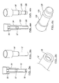
- the spray head is provided with a handle which actuates a plunger to draw up fluid through a dip tube connected thereto and extending in the container, and expelled via a nozzle.
- the spray heads are transported down a production line to a filling station, at which point the containers are filled with fluid and the spray head is connected to the container to form the finished product.
- the spray head is typically held by the end of the dip tube to maintain the spray head in a particular alignment ready for connection with the container.
- the dip tubes are typically flexible, it is possible for the spray head to become misaligned if the tubes bend as they are moved down the line. In addition, the tubes can become damaged if they are pushed too far or misaligned with the container when they are insetted.
- a belt is often used to guide or push the components together. Whete the nozzle is moveable between an on position and an off position, if the belt catches the nozzle during the connecting operation, the nozzle can be left partially or fully in the on position, such that leakage occurs during transportation.
- the erection means can knock the nozzle into the on position.
- a further problem in manufacturing trigger spray products is realised at the point at which the spray head is connected to the container.
- the two parts are provided with inter-engaging components, and the two parts are forced together such that they are locked together in a particular orientation, often in a non-releasable manner.
- the problem with this method is that if the two parts are not correctly aligned when they are associated, damage can be caused to the parts when they are forced together, or when they are forced together they are locked in an incorrect orientation which may have further implications in processing the product further and may make if difficult to transport.
- damage can be caused to the parts when they are forced together, or when they are forced together they are locked in an incorrect orientation which may have further implications in processing the product further and may make if difficult to transport.
- spray heads are connected to containers with flat surfaces, if the spray head is locked at an acute angle relative to the flat surface, the products cannot be packed as efficiently because the head protrudes at an angle preventing the products fitting together as well.
- An aim of the present invention is to provide a method of manufacturing a trigger sprayer so that it does not become damaged during manufacture.
- a further aim of the invention is to provide a closure mechanism which improves orientation of the spray head with the container.
- a method of manufacturing a trigger sprayer product including the steps of:-
- the length of the plunger is range-taking.
- the length of the plunger can be varied to suit the production line apparatus without affecting the dosage provided thereby.
- the length of the plunger ranges from around 20mm to around 100mm although it will be appreciated that these dimensions will also vary depending on the size of the container.
- the diameter of the plunger is substantially constant along the portion thereof which is variable in length.
- the portion of the plunger which is used to pick up the spray head only varies in length which makes it easier to handle during movement down the production line, as the production line apparatus does not have to be adapted to gripping products of different diameters.
- the spray head is provided with a housing, and the plunger extends therebeyond.
- the dip tube is applied at the filling point.
- the method allows the spray head to be supported by the mote resilient plunger during transportation thereof in the manufacturing system, and as the dip tubes are not inserted into the plungers until they reach the filling point there is less risk that they will become damaged during manufacture.
- the plunger is provided with an internal barb for retaining the dip tube therein.
- the dip tube is provided with an external barb to allow the dip tube to be retained externally on the plunger.
- dip tube and plunger are made from substantially the same material.
- At least a part of the plunger is made from low density polyethylene (LDPE) which is a relatively flexible material.
- LDPE low density polyethylene
- the dip tube is made from LDPE.
- At least a part of the plunger is made from polypropylene (PP), which is a relatively stiff material.
- PP polypropylene
- the upper part can be made from LDPE to provide better sealing properties, whereas the lower part can be made from PP to increase the resilience of the plunger.
- the plunger is provided with an internal shoulder to prevent further insertion of the dip tube.
- the spray head is provided with a nozzle, said nozzle provided with locking means.
- the nozzle is rotatably mounted on the body of the spray head.
- the nozzle is moveable between an on position and an off position.
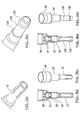
- the locking means includes one or more protrusions and/or recesses on the nozzle for engaging one or more protrusions and/or recesses on the body.
- the nozzle is frictionally locked in position when the protrusions on one of the nozzle or body are engaged with corresponding recesses on the other.
- the nozzle is unlocked by overcoming the frictional forces holding the nozzle in position.
- the nozzle is maintained in the off position during production and transportation, and is maintained in the on position when being used by a user.
- the outer perimeter of the nozzle is substantially square or rectangular, the nozzle being provided with four faces corresponding to four internal recesses.
- two protrusions are provided on the body for engaging the recesses to lock the nozzle in the on or off position.
- the faces are impressed with on and/or off indicators/symbols, which can typically be felt by touch of a user.
- Grooves or other gripping means on the corners of the nozzle can be provided to increase the grip a user can exert on the nozzle to turn the same between the positions.
- a trigger sprayer product including a spray head fitted to a container via a closure mechanism, said closure mechanism comprising an outer closure part and an inner closure part, said inner closure part being provided with a plurality of moveable lugs, said lugs being resiliently biased outwardly, and capable of being forced inwardly by the outer closure when the outer closure is forced thereover on connccting the spray head to the container, the outer closure being provided with a first plurality of protrusions for retaining the inner closure in an unassembled configuration, and a second plurality of protrusions for retaining the inner closure in an assembled configuration, characterised in that the lugs retain the spray head on the container.
- the container is provided with a neck onto which the spray head is fitted.
- the neck is provided with a ridge under which the lugs are forced to retain the spray head to the container.
- the lugs and the neck are provided with engagement means for maintaining the spray head in a particular orientation.
- the engagement means includes a plurality of engaging protrusions and recesses.
- the lugs are forced under the ridge of the container to hold the spray head thereonto, and arc provided with protrusions which engage ridges on the neck so that the orientation of the spray head relative to the container is maintained.
- the orientation can be adjusted by applying enough force to rotate the spray head, as the protrusions click over the neighbouring recesses.
- the inner closure is provided with one or more bore seals for engaging the neck of the container and/or a retaining ring provided on the display head.
- the spray head is releasable from the container, typically by overcoming the retaining force of the second plurality of protrusions retaining the inner closure in an assembled configuration.
- the spray head includes a weakened section and releasing means to enable the user to actuate the same to break the outer closure, thereby releasing the spray head from the container. As the broken outer closure cannot be refitted to the container this also provides means to detect tampering of the product.
- a two-click seal 61 is provided in the form of a number of protrusions and corresponding recesses to ensure the lower part is sealed to the upper part.
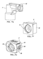
- Figures 7a-g illustrate further details of the nozzle 6 which is rotatably mounted on the spray head body 4, and moveable between on and off positions situated at 90 dcgtees to each other.
- the nozzle 6 is typically square, provided with four faces 98, each of which may be marked with symbols or indications to signify the on or off position to the user.
- the nozzle 6' may also be more rectangular in shape which further illustrates to the user which position the nozzle is in due to the asymmetric appearance.
- Locking means are provided in this example in the form of four recesses 90 on the rear of the nozzle, two of which are correspondingly engaged by two protrusions 92 disposed on the spray head body when locked in an on or off position.
- the locking means retains the nozzle in the off position during production and transportation thereof, with sufficient force to withstand knocks that would otherwise potentially move the nozzle to the on position.
- the user can overcome this frictional force to move the nozzle to the on position when required for use.
- Grooves 94 on the nozzle help the user to grip the nozzle to rotate the same, as do the on/off indications 96 which are impressed so as to allow the user to be able to increase the gripping force exertable on the nozzle.
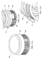
- Figures 8a-11c illustrate a closure mechanism including an outer closure part 70 and an inner closure part 72.
- the inner closure 72 is provided with a plurality of lugs 74 which arc designed to ride over and then grip under a ridge 82 provided on a container neck 84, to retain the spray head on the container.
- a first plurality of protrusions 78 maintain the inner closure in position so that it is ready to be assembled.
- the lugs are angled outwardly in their rest position, as shown in Figure 8a , but when the outer closure is pushed down over the inner closure during assembly and over the ridge 82 of the neck 84, the lugs are forced inwardly by the inner wall of the outer closure 70 as shown in Figure 8b , thereby gripping the neck 84 underneath the ridge 82.
- bore seals 80 may be provided to improve retention of the components to each other.
- the outer closure is provided with a second plurality of protrusions 76 which engage the lower edge of the inner closure to prevent relative movement of the outer closure 70.
- the neck 84 and lugs 74 are provided with engagement means in the form of, in this example, protrusions 86 on the lugs which engage recesses 88 on the neck.
- engagement means in the form of, in this example, protrusions 86 on the lugs which engage recesses 88 on the neck.
- protrusions engage the recesses to maintain the spray head in a particular orientation.
- the engagement is relatively weak, such that a user can overcome the engagement force and rotate the spray head to a different orientation relative to the container. The spray head can therefore be clicked into a new position via means similar to a ratchet mechanism.
- closure mechanism provides a means for connecting spray heads to containers while ensuring correctable relative orientation thereof.
- the outer closure 70 may be provided with a weakened section and releasing means in the form of tab 89. The user can pull the tab, once the closure is in the assembled position, to break the wall of the outer closure vertically along the weakened section, thereby releasing the spray head from the container.
- the broken outer closure provides evidence of tampering to the user, as is cannot be refitted to the container.
Landscapes
- Containers And Packaging Bodies Having A Special Means To Remove Contents (AREA)
Applications Claiming Priority (1)
| Application Number | Priority Date | Filing Date | Title |
|---|---|---|---|
| GBGB0715121.0A GB0715121D0 (en) | 2007-08-03 | 2007-08-03 | Improvements to trigger sprayer products |
Publications (2)
| Publication Number | Publication Date |
|---|---|
| EP2020264A2 true EP2020264A2 (fr) | 2009-02-04 |
| EP2020264A3 EP2020264A3 (fr) | 2009-02-25 |
Family
ID=38529228
Family Applications (1)
| Application Number | Title | Priority Date | Filing Date |
|---|---|---|---|
| EP08252628A Withdrawn EP2020264A3 (fr) | 2007-08-03 | 2008-08-04 | Améliorations portant sur des dispositifs à gachette. |
Country Status (2)
| Country | Link |
|---|---|
| EP (1) | EP2020264A3 (fr) |
| GB (1) | GB0715121D0 (fr) |
Cited By (3)
| Publication number | Priority date | Publication date | Assignee | Title |
|---|---|---|---|---|
| WO2012035445A1 (fr) * | 2010-09-16 | 2012-03-22 | Guala Dispensing S.P.A. | Distributeur de type à gâchette |
| US20120234870A1 (en) * | 2011-03-15 | 2012-09-20 | Good Robert J | Dip tube connectors and pump systems using the same |
| CN110461480A (zh) * | 2016-09-12 | 2019-11-15 | 里克有限责任公司 | 扳机喷雾器 |
Family Cites Families (12)
| Publication number | Priority date | Publication date | Assignee | Title |
|---|---|---|---|---|
| GB692254A (en) * | 1948-08-06 | 1953-06-03 | New Hygiene Ltd | Improvements in or relating to apparatus for atomizing or spraying liquids |
| FR2528328B1 (fr) * | 1982-06-11 | 1985-11-22 | Valve Precision Sarl | Dispositif de pulverisation pour liquides |
| JPH0678108B2 (ja) * | 1989-03-15 | 1994-10-05 | 澁谷工業株式会社 | ディスペンサの方向規制装置 |
| DE4338791C2 (de) * | 1993-11-12 | 1996-05-30 | Innocos Gmbh | Verschlußvorrichtung für einen Behälter mit einer handbetätigten Pumpe |
| US6364172B1 (en) * | 1998-12-10 | 2002-04-02 | Afa Polytek, B.V. | Liquid dispenser and assembly methods therefor |
| US6227411B1 (en) * | 1999-08-13 | 2001-05-08 | Saint-Gobain Calmar Inc. | Fluid dispenser with child-resistant nozzle assembly |
| JP2001315707A (ja) * | 2000-04-28 | 2001-11-13 | Lion Corp | ポンプ式ディスペンサーの装着装置 |
| US6776311B2 (en) * | 2002-11-13 | 2004-08-17 | Emsar, Incorporated | Dispenser assembly for a fragrance or personal care bottle and a method of assembling same |
| FR2859983B1 (fr) * | 2003-09-22 | 2006-03-10 | Valois Sas | Dispositif de fixation et procede de montage pour fixer un organe de distribution sur une ouverture de reservoir |
| DE202004003671U1 (de) * | 2004-03-08 | 2005-07-21 | Ophardt Hygiene-Technik Gmbh + Co. Kg | Dosierpumpe |
| FR2891533B1 (fr) * | 2005-10-04 | 2007-12-07 | Valois Sas | Organe de recouvrement, procede de fabrication d'un tel organe et distributeur de produit fluide utilisant un tel organe. |
| US20070132149A1 (en) * | 2005-11-29 | 2007-06-14 | Hildebrand George R | Methods of making foam nozzles for trigger dispensers |
-
2007
- 2007-08-03 GB GBGB0715121.0A patent/GB0715121D0/en not_active Ceased
-
2008
- 2008-08-04 EP EP08252628A patent/EP2020264A3/fr not_active Withdrawn
Cited By (16)
| Publication number | Priority date | Publication date | Assignee | Title |
|---|---|---|---|---|
| US9919326B2 (en) | 2010-09-16 | 2018-03-20 | The Clorox Company | Trigger dispenser |
| US8870033B2 (en) | 2010-09-16 | 2014-10-28 | Guala Dispensing S.P.A. | Trigger dispenser |
| US8931668B2 (en) | 2010-09-16 | 2015-01-13 | The Clorox Company | Trigger dispenser device |
| WO2012035445A1 (fr) * | 2010-09-16 | 2012-03-22 | Guala Dispensing S.P.A. | Distributeur de type à gâchette |
| US11571703B2 (en) | 2010-09-16 | 2023-02-07 | The Clorox Company | Trigger dispenser |
| US20120234870A1 (en) * | 2011-03-15 | 2012-09-20 | Good Robert J | Dip tube connectors and pump systems using the same |
| US20120234872A1 (en) * | 2011-03-15 | 2012-09-20 | Meadwestvaco Calmar, Inc. | Dip tube connectors and pump systems using the same |
| US9827581B2 (en) * | 2011-03-15 | 2017-11-28 | Silgan Dispensing Systems Corporation | Dip tube connectors and pump systems using the same |
| US11406996B2 (en) | 2011-03-15 | 2022-08-09 | The Clorox Company | Dip tube connectors and pump systems using the same |
| US10124357B2 (en) * | 2011-03-15 | 2018-11-13 | Silgan Dispensing Systems Corporation | Dip tube connectors and pump systems using the same |
| US10646888B2 (en) | 2011-03-15 | 2020-05-12 | Silgan Dispensing Systems Corporation | Dip tube connectors and pump systems using the same |
| US11648575B2 (en) | 2011-03-15 | 2023-05-16 | The Clorox Company | Dip tube connectors and pump systems using the same |
| US10870122B2 (en) | 2011-03-15 | 2020-12-22 | The Clorox Company | Dip tube connectors and pump systems using the same |
| CN110461480A (zh) * | 2016-09-12 | 2019-11-15 | 里克有限责任公司 | 扳机喷雾器 |
| US11247221B2 (en) | 2016-09-12 | 2022-02-15 | Rieke Llc | Trigger sprayer |
| EP3509755A4 (fr) * | 2016-09-12 | 2020-05-13 | Rieke Corporation | Pulvérisateur à gâchette |
Also Published As
| Publication number | Publication date |
|---|---|
| EP2020264A3 (fr) | 2009-02-25 |
| GB0715121D0 (en) | 2007-09-12 |
Similar Documents
| Publication | Publication Date | Title |
|---|---|---|
| EP3683169B1 (fr) | Procédé d'assemblage d'un système de distribution pour distribuer un milieu fluide | |
| US2686081A (en) | Plastic pressurized container and dispenser | |
| US12296153B2 (en) | Method of sealing a syringe barrel | |
| BR112014030467B1 (pt) | Válvula para descarregar um fluido, método para descarregar um fluido a partir da mesma, uso de uma válvula e seringa | |
| US20150272197A1 (en) | Container | |
| JP2015501766A (ja) | ライナベースの移送および分配コンテナのための閉塞具/コネクタおよびライナベースの移送および分配コンテナを充填する方法 | |
| EP3604161B1 (fr) | Couvercle destiné à un récipient de stockage de matériau liquide, et récipient de stockage de matériau liquide | |
| JP2016515985A (ja) | 容器 | |
| US20160100703A1 (en) | Universal threaded bottle cap and straw | |
| US9617054B2 (en) | Dual thread nozzle and cap assembly for dispensing pouch | |
| GB2058726A (en) | Glue dispenser | |
| US10370178B2 (en) | Single action dispensing device with sliding sleeve having a plug | |
| EP2020264A2 (fr) | Améliorations portant sur des dispositifs à gachette | |
| US11319118B2 (en) | Child-resistant locking cap for laminated tubes with improved locking cap insert to reduce substance leakage after the locking cap is closed | |
| US20130105515A1 (en) | Dispenser system | |
| TWI630150B (zh) | 配件、用於施配系統的配件接合器及其製造方法 | |
| US20080035597A1 (en) | Child Resistant Closure | |
| CN106998888B (zh) | 具有改进的开启系统的容器 | |
| AU2021245680A1 (en) | Medical syringe barrel, and packaging for same | |
| CN108883870A (zh) | 气溶胶阀构造 | |
| KR101279013B1 (ko) | 휴대용 향수용기 | |
| US20070078390A1 (en) | Injection syringe | |
| US9849248B2 (en) | Dispenser assembly for liquids comprising flexible barrel and rigid plunger | |
| JP2006193172A (ja) | 打栓型歯科用液体収納容器 | |
| US20180105330A1 (en) | Snap cap with deep plug and seal overmold |
Legal Events
| Date | Code | Title | Description |
|---|---|---|---|
| PUAI | Public reference made under article 153(3) epc to a published international application that has entered the european phase |
Free format text: ORIGINAL CODE: 0009012 |
|
| PUAL | Search report despatched |
Free format text: ORIGINAL CODE: 0009013 |
|
| AK | Designated contracting states |
Kind code of ref document: A2 Designated state(s): AT BE BG CH CY CZ DE DK EE ES FI FR GB GR HR HU IE IS IT LI LT LU LV MC MT NL NO PL PT RO SE SI SK TR |
|
| AX | Request for extension of the european patent |
Extension state: AL BA MK RS |
|
| AK | Designated contracting states |
Kind code of ref document: A3 Designated state(s): AT BE BG CH CY CZ DE DK EE ES FI FR GB GR HR HU IE IS IT LI LT LU LV MC MT NL NO PL PT RO SE SI SK TR |
|
| AX | Request for extension of the european patent |
Extension state: AL BA MK RS |
|
| 17P | Request for examination filed |
Effective date: 20090811 |
|
| 17Q | First examination report despatched |
Effective date: 20090902 |
|
| AKX | Designation fees paid |
Designated state(s): AT BE BG CH CY CZ DE DK EE ES FI FR GB GR HR HU IE IS IT LI LT LU LV MC MT NL NO PL PT RO SE SI SK TR |
|
| STAA | Information on the status of an ep patent application or granted ep patent |
Free format text: STATUS: THE APPLICATION IS DEEMED TO BE WITHDRAWN |
|
| 18D | Application deemed to be withdrawn |
Effective date: 20100312 |