EP2020272A1 - Procédé et dispositif de soudage de soudures circulaires - Google Patents
Procédé et dispositif de soudage de soudures circulaires Download PDFInfo
- Publication number
- EP2020272A1 EP2020272A1 EP08013744A EP08013744A EP2020272A1 EP 2020272 A1 EP2020272 A1 EP 2020272A1 EP 08013744 A EP08013744 A EP 08013744A EP 08013744 A EP08013744 A EP 08013744A EP 2020272 A1 EP2020272 A1 EP 2020272A1
- Authority
- EP
- European Patent Office
- Prior art keywords
- root
- welding
- nozzle
- gap joint
- components
- Prior art date
- Legal status (The legal status is an assumption and is not a legal conclusion. Google has not performed a legal analysis and makes no representation as to the accuracy of the status listed.)
- Ceased
Links
- 238000003466 welding Methods 0.000 title claims abstract description 66
- 238000000034 method Methods 0.000 title claims abstract description 29
- 238000002360 preparation method Methods 0.000 claims abstract description 9
- 229910000831 Steel Inorganic materials 0.000 claims abstract description 5
- 239000010959 steel Substances 0.000 claims abstract description 5
- 229910045601 alloy Inorganic materials 0.000 claims abstract description 3
- 239000000956 alloy Substances 0.000 claims abstract description 3
- 230000008878 coupling Effects 0.000 claims description 18
- 238000010168 coupling process Methods 0.000 claims description 18
- 238000005859 coupling reaction Methods 0.000 claims description 18
- 239000000463 material Substances 0.000 claims description 6
- PXHVJJICTQNCMI-UHFFFAOYSA-N Nickel Chemical compound [Ni] PXHVJJICTQNCMI-UHFFFAOYSA-N 0.000 claims description 4
- 239000000919 ceramic Substances 0.000 claims description 4
- 239000010453 quartz Substances 0.000 claims description 4
- VYPSYNLAJGMNEJ-UHFFFAOYSA-N silicon dioxide Inorganic materials O=[Si]=O VYPSYNLAJGMNEJ-UHFFFAOYSA-N 0.000 claims description 4
- RYGMFSIKBFXOCR-UHFFFAOYSA-N Copper Chemical compound [Cu] RYGMFSIKBFXOCR-UHFFFAOYSA-N 0.000 claims description 2
- 229910000881 Cu alloy Inorganic materials 0.000 claims description 2
- 229910010293 ceramic material Inorganic materials 0.000 claims description 2
- 239000004020 conductor Substances 0.000 claims description 2
- 229910052802 copper Inorganic materials 0.000 claims description 2
- 239000010949 copper Substances 0.000 claims description 2
- 229910052759 nickel Inorganic materials 0.000 claims description 2
- WFKWXMTUELFFGS-UHFFFAOYSA-N tungsten Chemical compound [W] WFKWXMTUELFFGS-UHFFFAOYSA-N 0.000 abstract description 10
- 239000011261 inert gas Substances 0.000 abstract description 8
- 229910052721 tungsten Inorganic materials 0.000 abstract description 6
- 239000010937 tungsten Substances 0.000 abstract description 6
- 230000008569 process Effects 0.000 abstract description 5
- 230000008901 benefit Effects 0.000 description 3
- 238000011161 development Methods 0.000 description 2
- 230000018109 developmental process Effects 0.000 description 2
- 239000007772 electrode material Substances 0.000 description 2
- 239000007789 gas Substances 0.000 description 2
- 230000035939 shock Effects 0.000 description 2
- 238000004904 shortening Methods 0.000 description 2
- 241001156002 Anthonomus pomorum Species 0.000 description 1
- 238000004026 adhesive bonding Methods 0.000 description 1
- 230000006378 damage Effects 0.000 description 1
- 230000007547 defect Effects 0.000 description 1
- 238000001514 detection method Methods 0.000 description 1
- 238000005516 engineering process Methods 0.000 description 1
- KEUKAQNPUBYCIC-UHFFFAOYSA-N ethaneperoxoic acid;hydrogen peroxide Chemical compound OO.CC(=O)OO KEUKAQNPUBYCIC-UHFFFAOYSA-N 0.000 description 1
- 230000004927 fusion Effects 0.000 description 1
- 238000003780 insertion Methods 0.000 description 1
- 230000037431 insertion Effects 0.000 description 1
- 238000004519 manufacturing process Methods 0.000 description 1
- 229910000734 martensite Inorganic materials 0.000 description 1
- 230000009467 reduction Effects 0.000 description 1
- 230000008439 repair process Effects 0.000 description 1
- 230000002123 temporal effect Effects 0.000 description 1
Images
Classifications
-
- B—PERFORMING OPERATIONS; TRANSPORTING
- B23—MACHINE TOOLS; METAL-WORKING NOT OTHERWISE PROVIDED FOR
- B23K—SOLDERING OR UNSOLDERING; WELDING; CLADDING OR PLATING BY SOLDERING OR WELDING; CUTTING BY APPLYING HEAT LOCALLY, e.g. FLAME CUTTING; WORKING BY LASER BEAM
- B23K9/00—Arc welding or cutting
- B23K9/02—Seam welding; Backing means; Inserts
- B23K9/0213—Narrow gap welding
-
- B—PERFORMING OPERATIONS; TRANSPORTING
- B23—MACHINE TOOLS; METAL-WORKING NOT OTHERWISE PROVIDED FOR
- B23K—SOLDERING OR UNSOLDERING; WELDING; CLADDING OR PLATING BY SOLDERING OR WELDING; CUTTING BY APPLYING HEAT LOCALLY, e.g. FLAME CUTTING; WORKING BY LASER BEAM
- B23K9/00—Arc welding or cutting
- B23K9/02—Seam welding; Backing means; Inserts
- B23K9/028—Seam welding; Backing means; Inserts for curved planar seams
- B23K9/0282—Seam welding; Backing means; Inserts for curved planar seams for welding tube sections
- B23K9/0286—Seam welding; Backing means; Inserts for curved planar seams for welding tube sections with an electrode moving around the fixed tube during the welding operation
-
- B—PERFORMING OPERATIONS; TRANSPORTING
- B23—MACHINE TOOLS; METAL-WORKING NOT OTHERWISE PROVIDED FOR
- B23K—SOLDERING OR UNSOLDERING; WELDING; CLADDING OR PLATING BY SOLDERING OR WELDING; CUTTING BY APPLYING HEAT LOCALLY, e.g. FLAME CUTTING; WORKING BY LASER BEAM
- B23K9/00—Arc welding or cutting
- B23K9/16—Arc welding or cutting making use of shielding gas
- B23K9/167—Arc welding or cutting making use of shielding gas and of a non-consumable electrode
-
- B—PERFORMING OPERATIONS; TRANSPORTING
- B23—MACHINE TOOLS; METAL-WORKING NOT OTHERWISE PROVIDED FOR
- B23K—SOLDERING OR UNSOLDERING; WELDING; CLADDING OR PLATING BY SOLDERING OR WELDING; CUTTING BY APPLYING HEAT LOCALLY, e.g. FLAME CUTTING; WORKING BY LASER BEAM
- B23K9/00—Arc welding or cutting
- B23K9/24—Features related to electrodes
- B23K9/28—Supporting devices for electrodes
- B23K9/29—Supporting devices adapted for making use of shielding means
- B23K9/291—Supporting devices adapted for making use of shielding means the shielding means being a gas
-
- B—PERFORMING OPERATIONS; TRANSPORTING
- B23—MACHINE TOOLS; METAL-WORKING NOT OTHERWISE PROVIDED FOR
- B23K—SOLDERING OR UNSOLDERING; WELDING; CLADDING OR PLATING BY SOLDERING OR WELDING; CUTTING BY APPLYING HEAT LOCALLY, e.g. FLAME CUTTING; WORKING BY LASER BEAM
- B23K9/00—Arc welding or cutting
- B23K9/24—Features related to electrodes
- B23K9/28—Supporting devices for electrodes
- B23K9/29—Supporting devices adapted for making use of shielding means
- B23K9/291—Supporting devices adapted for making use of shielding means the shielding means being a gas
- B23K9/296—Supporting devices adapted for making use of shielding means the shielding means being a gas using non-consumable electrodes
-
- B—PERFORMING OPERATIONS; TRANSPORTING
- B23—MACHINE TOOLS; METAL-WORKING NOT OTHERWISE PROVIDED FOR
- B23K—SOLDERING OR UNSOLDERING; WELDING; CLADDING OR PLATING BY SOLDERING OR WELDING; CUTTING BY APPLYING HEAT LOCALLY, e.g. FLAME CUTTING; WORKING BY LASER BEAM
- B23K2101/00—Articles made by soldering, welding or cutting
- B23K2101/04—Tubular or hollow articles
- B23K2101/10—Pipe-lines
Definitions
- the invention relates to a method for welding round seams for connecting two components, in particular of thick-walled components or pipes, wherein a root is produced in a narrow gap between the components and the narrow gap is then filled by fully mechanical orbital welding. Furthermore, the invention relates to a device for welding round seams for connecting two components, in particular of thick-walled components or pipes, with a TIG torch having a nozzle, in particular manually guided TIG torch, the nozzle having an electrode arranged at least in sections inside the nozzle having.
- devices for welding round seams for connecting two components which have a TIG torch having a nozzle, wherein the nozzle has an at least partially disposed within the nozzle electrode.
- TIG orbital narrow gap welding compared to building site welding methods that can be used comparably is the result of the significant reduction in the seam volume.
- a very high temporal and technical effort in preparing the seam preparation due to low tolerance specifications and in particular for aligning the seams due to extremely low tolerances required for assembly prior to welding in terms of edge offset and seam root clearance.
- This elaborate preparation with regard to the positioning of the components to be connected serves for the reliable detection of the root when fully mechanical TIG orbital welding is used in order to avoid welding defects.
- this significant amount of time to maintain the tolerance specifications, which allow the use of fully mechanical root welding but a significant part of the advantage of TIG orbital welding is repealed. This is especially true for thick-walled components, as a potentially required repair is increasingly costly, taking into account that the wall thickness of the components to be joined is often 100 mm and more.
- the present invention is therefore based on the object of specifying a method and a device for welding round seams, according to which a secure welded connection can be realized in a simple manner.
- the above object is achieved on the one hand by a method having the features of patent claim 1. Thereafter, the method of the aforementioned type is configured and further developed such that the root is manually welded by means of the TIG method - m-141.
- the root is manually welded in accordance with the invention by means of the TIG process - m-141.
- the effort in terms of setting and positioning of the components is considerably reduced, since the existing for manual welding tolerance specifications from a procedural point of view are far from as strict as it is the case of fully mechanical orbital welding by means of the orbital device. Rather, by means of manual welding, compared to fully mechanical welding, significantly increased manufacturing reliability in root welding under reproducible conditions is possible. The stem and seam preparation tolerances are far greater.
- orbital welding is TIG welding - v-141. This is therefore a tungsten inert gas welding.
- At least one supporting layer on the root could be manually welded by means of the TIG method - m-141.
- at least one support layer to be arranged on the root could also be welded manually.
- this width could be selected between 0 and 5 mm. As a result, a secure and very stable root can be generated.
- the chamfering of the narrow gap joint in the filling layer region could be selected as a steep flank with a flank angle of 0 ° to a maximum of 5 °.
- a secure fusion of the root and, on the other hand, a low gap volume to be filled is achieved.
- more than 50% of the depth of the narrow gap joint could be selected as such steep flank.
- the components to be joined could have wall thicknesses of 45 mm or more and / or be made of a steel or nickel-based alloy.
- steel for example, ferritic or martensitic steels come into question.
- the above object is further achieved by a device having the features of claim 9. Thereafter, the device of the type mentioned is designed and further developed such that the nozzle has at least at its free end an oval or rectangular cross-sectional shape.
- the nozzle has an oval or rectangular cross-sectional shape at least at its free end.
- This oval or rectangular cross-sectional shape offers in comparison to known round cross-sectional shapes on the one hand a particularly safe and easy access even in narrow gap joints and on the other hand sufficient for the welding process internal volume of the nozzle. Consequently, with the nozzle according to the invention a secure welded connection can be realized in a simple manner.
- the nozzle could have a coupling region for direct or indirect coupling to a burner body and an end region having the free end, and the end region and the coupling region could preferably be reversibly connected to one another.
- This at least two-part design of the nozzle offers a high flexibility and adaptability of the nozzle to different circumstances and situations, in particular with regard to the width and depth of a narrow gap joint.
- different end regions can be connectable with one and the same coupling region.
- a replacement of a worn end region could be made possible by further use of an existing coupling region in a simple manner, which can save material and costs.
- the end region could be positively and / or positively connected to the coupling region, in which case adhesive bonding is also conceivable.
- the end region - preferably positive and / or non-positive - could be plugged or screwed onto the coupling region or inserted or screwed into the coupling region.
- a simple interchangeability of the end portion is realized.
- the nozzle could be made of a quartz material or of a ceramic material, preferably a drawn ceramic.
- the free end or the end region of the nozzle can be adapted in terms of its length to the particular application.
- the free end or the end area of the nozzle could be at least 45 mm long.
- the free end or end portion of the nozzle could be at least 50mm or at least 55mm in length.
- the nozzle could be assigned a support device for the electrode.
- a support device for the electrode.
- accidental contact of the free end or the end portion of the nozzle could be prevented by the electrode.
- Such unwanted contact depending on the nozzle material used, could result in thermal shock and destruction of the free end or end portion of the nozzle.
- the support means could guide the electrode opposite the free end or end portion of the nozzle.
- the support means could be formed of poor thermal conductivity material.
- the support device could have a ceramic or quartz ring surrounding the electrode.
- the support means could be arranged in the end region or near the free end of the nozzle. This allows a particularly secure guidance of the electrode.
- the electrode could be assigned an electrode guide, which is extended up to a further component of the burner, in particular up to a gas lens or clamping sleeve. As a result, a centering of the electrode could be achieved.
- the electrode could have an adapter piece for effective shortening of the electrode relative to the total length required by the nozzle length, so that only a front end of the electrode could be formed from the actual electrode material, for example tungsten.
- the adapter piece could be formed from an electrically particularly highly conductive material, which in a further advantageous manner copper or a copper alloy offers.
- the adapter piece could be connected in a simple manner mechanically or cohesively to the electrode in order to ensure a secure connection between the adapter piece and the actual electrode material.
- the adapter piece could be fixed in or on a clamping sleeve of the burner.
- a shortening of the actual tungsten electrode thus achieved is easily possible with an electrode length between clamping and arc of more than 50 mm.
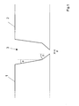
- Fig. 1 shows a schematic representation of an application for an embodiment of the method according to the invention for welding round seams for connecting two components 1 and 2.
- a root in a narrow gap joint 3 between the components 1 and 2 generates and the narrow gap joint 3 is then filled by fully mechanical orbital welding.
- Fig. 1 For the sake of simplicity, only a section of the components 1 and 2 in the area of the narrow gap joint 3 is shown.
- the root is manually welded using the TIG process - m-141.
- the width d of a root gap in the narrow gap joint 3 is selected between 0 and 5 mm. Furthermore, the chamfering of the narrow gap joint 3 in the filling layer area is selected with a flank angle ⁇ of at most 5 °. The chamfering of the narrow gap joint 3 in the root area is selected with a V-seam preparation with an angle ⁇ of about 30 °.
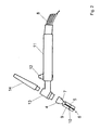
- Fig. 2 shows a schematic representation of the basic structure of a burner of an embodiment of a device according to the invention for welding round seams.
- the burner has a nozzle 4 with an electrode 5 arranged inside the nozzle 4.
- the nozzle 4 at its free end 6 has a rectangular cross-sectional shape. Due to this cross-sectional shape is a easy insertion of the nozzle in the narrow gap joint 3 between two components 1 and 2 to be connected possible.
- the nozzle 4 has a coupling region 7 for coupling or screwing to a burner body 13 and an end region 9 having the free end 6. Furthermore, the end region 9 and the coupling region 7 are reversibly connected to one another. Specifically, the end portion 9 is attachable to the coupling region 7 to form a suitably long nozzle 4, with which the root can be welded manually in a narrow gap joint 3.
- the end portion 9 of the nozzle 4 is at least 50 mm long.
- the nozzle 4 further has a supporting device for the electrode 5 in the form of a ring 10, which surrounds the electrode 5.
- the burner furthermore has a handle 11 with a pushbutton switch 12 arranged thereon and a connection region 8.
- the handle 11 is arranged on a burner body 13, on which a burner cap 14 is inserted.
- gas or water-cooled burners are used in TIG welding, depending on the required arc performance.
Landscapes
- Engineering & Computer Science (AREA)
- Physics & Mathematics (AREA)
- Plasma & Fusion (AREA)
- Mechanical Engineering (AREA)
- Arc Welding In General (AREA)
- Butt Welding And Welding Of Specific Article (AREA)
Applications Claiming Priority (1)
| Application Number | Priority Date | Filing Date | Title |
|---|---|---|---|
| DE102007036289A DE102007036289A1 (de) | 2007-07-31 | 2007-07-31 | Verfahren und eine Vorrichtung zum Schweißen von Rundnähten |
Publications (1)
| Publication Number | Publication Date |
|---|---|
| EP2020272A1 true EP2020272A1 (fr) | 2009-02-04 |
Family
ID=39885054
Family Applications (1)
| Application Number | Title | Priority Date | Filing Date |
|---|---|---|---|
| EP08013744A Ceased EP2020272A1 (fr) | 2007-07-31 | 2008-07-31 | Procédé et dispositif de soudage de soudures circulaires |
Country Status (2)
| Country | Link |
|---|---|
| EP (1) | EP2020272A1 (fr) |
| DE (1) | DE102007036289A1 (fr) |
Cited By (12)
| Publication number | Priority date | Publication date | Assignee | Title |
|---|---|---|---|---|
| RU2545869C2 (ru) * | 2009-06-10 | 2015-04-10 | Сименс Акциенгезелльшафт | Способ сварки для валов при вертикальной оси вращения |
| CN104668744A (zh) * | 2015-02-12 | 2015-06-03 | 中国科学院等离子体物理研究所 | 用于厚壁核聚变真空室的自动tig焊接工艺 |
| CN105195869A (zh) * | 2015-11-12 | 2015-12-30 | 上海电气核电设备有限公司 | 一种镍基焊丝异种金属冷丝tig全位置焊接方法 |
| CN105522260A (zh) * | 2016-02-03 | 2016-04-27 | 江苏电力装备有限公司 | 厚壁管道窄间隙氩弧自动焊焊接方法 |
| US9517524B2 (en) | 2013-11-12 | 2016-12-13 | Lincoln Global, Inc. | Welding wire spool support |
| US9527153B2 (en) | 2013-03-14 | 2016-12-27 | Lincoln Global, Inc. | Camera and wire feed solution for orbital welder system |
| CN106378518A (zh) * | 2016-11-30 | 2017-02-08 | 东方电气集团东方锅炉股份有限公司 | 一种用于大直径薄壁不锈钢筒体工件环缝的tig焊方法 |
| US9731385B2 (en) | 2013-11-12 | 2017-08-15 | Lincoln Global, Inc. | Orbital welder with wire height adjustment assembly |
| US9770775B2 (en) | 2013-11-11 | 2017-09-26 | Lincoln Global, Inc. | Orbital welding torch systems and methods with lead/lag angle stop |
| US9969025B2 (en) | 2011-11-18 | 2018-05-15 | Lincoln Global, Inc. | System for mounting a tractor unit on a guide track |
| CN112975053A (zh) * | 2021-03-04 | 2021-06-18 | 双龙集团有限公司 | 一种镍基合金的筒体及其制造方法、犁刀式混合机 |
| CN115007981A (zh) * | 2022-06-08 | 2022-09-06 | 国家石油天然气管网集团有限公司 | 一种窄坡口低应力的厚壁管道对焊方法 |
Citations (6)
| Publication number | Priority date | Publication date | Assignee | Title |
|---|---|---|---|---|
| CA1055120A (fr) * | 1976-04-29 | 1979-05-22 | Canadian General Electric Company Limited | Pistolet a souder dans des entre-deux etroits et profonds |
| EP0025989A1 (fr) * | 1979-09-20 | 1981-04-01 | Westinghouse Electric Corporation | Torche de soudage à l'arc à gaz-tungstène et procédé de soudage |
| US4343983A (en) * | 1979-09-20 | 1982-08-10 | Westinghouse Electric Corp. | Non-consumable composite welding electrode |
| EP0819495A2 (fr) * | 1996-06-20 | 1998-01-21 | General Electric Company | Dispositif de jonction de composants métalliques utilisant une buse de charge large et mince |
| EP1136169A1 (fr) * | 1999-07-12 | 2001-09-26 | Hitachi Construction Machinery Co., Ltd. | Procede de soudage et dispositif de soudage a ecartement serre |
| US20060201915A1 (en) * | 2005-03-09 | 2006-09-14 | Takeshi Obana | Welding process for stainless steel piping |
Family Cites Families (8)
| Publication number | Priority date | Publication date | Assignee | Title |
|---|---|---|---|---|
| DE2920917C3 (de) * | 1979-05-23 | 1982-03-25 | Umbert 7519 Eppingen Schulz | Schutzgasschweißbrenner |
| DD148598A1 (de) * | 1980-01-17 | 1981-06-03 | Joerg Steeger | Vorrichtung zum verkuerzen der reststuecke von schweissstaeben |
| DD246932A1 (de) * | 1986-02-26 | 1987-06-24 | Leipzig Chemieanlagen | Vorrichtung zur schweissbadsicherung zum schweissen von rundnaehten an gekruemmten bauteilen |
| DD265575A1 (de) * | 1987-10-16 | 1989-03-08 | Berlin Fahrzeugausruestung | Vorrichtung zur badsicherung beim lichtbogenschweissen |
| US5030812A (en) * | 1989-06-13 | 1991-07-09 | Nkk Corporation | Method for one-side root pass welding of a pipe joint |
| ES2129086T3 (es) * | 1994-01-29 | 1999-06-01 | Asea Brown Boveri | Procedimiento para unir piezas metalicas por medio de soldadura por fusion con arco voltaico. |
| DE19729781C1 (de) * | 1997-07-11 | 1998-09-10 | Ruhr Oel Gmbh | Verfahren zum Schweißen von Formkörpern aus aufgekohltem, hitzebeständigem Stahl |
| US6754956B1 (en) * | 2002-12-04 | 2004-06-29 | General Electric Company | Methods for manufacturing a nozzle box assembly for a steam turbine |
-
2007
- 2007-07-31 DE DE102007036289A patent/DE102007036289A1/de not_active Ceased
-
2008
- 2008-07-31 EP EP08013744A patent/EP2020272A1/fr not_active Ceased
Patent Citations (6)
| Publication number | Priority date | Publication date | Assignee | Title |
|---|---|---|---|---|
| CA1055120A (fr) * | 1976-04-29 | 1979-05-22 | Canadian General Electric Company Limited | Pistolet a souder dans des entre-deux etroits et profonds |
| EP0025989A1 (fr) * | 1979-09-20 | 1981-04-01 | Westinghouse Electric Corporation | Torche de soudage à l'arc à gaz-tungstène et procédé de soudage |
| US4343983A (en) * | 1979-09-20 | 1982-08-10 | Westinghouse Electric Corp. | Non-consumable composite welding electrode |
| EP0819495A2 (fr) * | 1996-06-20 | 1998-01-21 | General Electric Company | Dispositif de jonction de composants métalliques utilisant une buse de charge large et mince |
| EP1136169A1 (fr) * | 1999-07-12 | 2001-09-26 | Hitachi Construction Machinery Co., Ltd. | Procede de soudage et dispositif de soudage a ecartement serre |
| US20060201915A1 (en) * | 2005-03-09 | 2006-09-14 | Takeshi Obana | Welding process for stainless steel piping |
Non-Patent Citations (1)
| Title |
|---|
| LAMBS R ET AL: "NARROW GAP REPAIR WELDING IN NUCLEAR POWER PLANTS", WELDING AND METAL FABRICATION, IPC LTD. HAYWARDS HEATH, GB, vol. 66, no. 9, 1 October 1998 (1998-10-01), pages 21/22, XP000781907, ISSN: 0043-2245 * |
Cited By (12)
| Publication number | Priority date | Publication date | Assignee | Title |
|---|---|---|---|---|
| RU2545869C2 (ru) * | 2009-06-10 | 2015-04-10 | Сименс Акциенгезелльшафт | Способ сварки для валов при вертикальной оси вращения |
| US9969025B2 (en) | 2011-11-18 | 2018-05-15 | Lincoln Global, Inc. | System for mounting a tractor unit on a guide track |
| US9527153B2 (en) | 2013-03-14 | 2016-12-27 | Lincoln Global, Inc. | Camera and wire feed solution for orbital welder system |
| US9770775B2 (en) | 2013-11-11 | 2017-09-26 | Lincoln Global, Inc. | Orbital welding torch systems and methods with lead/lag angle stop |
| US9517524B2 (en) | 2013-11-12 | 2016-12-13 | Lincoln Global, Inc. | Welding wire spool support |
| US9731385B2 (en) | 2013-11-12 | 2017-08-15 | Lincoln Global, Inc. | Orbital welder with wire height adjustment assembly |
| CN104668744A (zh) * | 2015-02-12 | 2015-06-03 | 中国科学院等离子体物理研究所 | 用于厚壁核聚变真空室的自动tig焊接工艺 |
| CN105195869A (zh) * | 2015-11-12 | 2015-12-30 | 上海电气核电设备有限公司 | 一种镍基焊丝异种金属冷丝tig全位置焊接方法 |
| CN105522260A (zh) * | 2016-02-03 | 2016-04-27 | 江苏电力装备有限公司 | 厚壁管道窄间隙氩弧自动焊焊接方法 |
| CN106378518A (zh) * | 2016-11-30 | 2017-02-08 | 东方电气集团东方锅炉股份有限公司 | 一种用于大直径薄壁不锈钢筒体工件环缝的tig焊方法 |
| CN112975053A (zh) * | 2021-03-04 | 2021-06-18 | 双龙集团有限公司 | 一种镍基合金的筒体及其制造方法、犁刀式混合机 |
| CN115007981A (zh) * | 2022-06-08 | 2022-09-06 | 国家石油天然气管网集团有限公司 | 一种窄坡口低应力的厚壁管道对焊方法 |
Also Published As
| Publication number | Publication date |
|---|---|
| DE102007036289A1 (de) | 2009-02-05 |
Similar Documents
| Publication | Publication Date | Title |
|---|---|---|
| DE102007036289A1 (de) | Verfahren und eine Vorrichtung zum Schweißen von Rundnähten | |
| EP2226146B1 (fr) | Procédé d'assemblage de deux pièces métalliques, notamment symétriques de révolution, par soudage TIG et appareil pour la mise en oeuvre d'un tel procédé | |
| EP3188871B1 (fr) | Matériau de soudage et procédé de production d'un assemblage au moyen d'une liaison par matière | |
| EP0519223B1 (fr) | Raccord étanche aux gaz entre tuyaux de faibles diamètres, procédé et appareil de fabrication | |
| DE4008675A1 (de) | Elektromagnetisch betaetigbares ventil | |
| DE69732000T2 (de) | Vorrichtung zum Verbinden metallischer Bauteile mit einer breiten dünnen Zusatzdüse | |
| EP2216122A1 (fr) | Tuyau à gaz de protection et tuyau de contact d'un dispositif destiné à la soudure améliorée d'intervalles serrés | |
| DE102010028772A1 (de) | Verfahren und Vorrichtung zum Verbinden zweier Drahtenden | |
| DE102019100581A1 (de) | Gasdüse zum Ausströmen eines Schutzgasstromes und Brennerhals mit einer Gasdüse | |
| EP2216123A1 (fr) | Tuyau à gaz de protection et tuyau de contact d'un dispositif destiné à la soudure améliorée d'intervalles serrés | |
| DE3615947C1 (en) | Welding and centring ring | |
| EP1606599B1 (fr) | Element de mesure presentant l'elasticite d'un ressort, pourvu d'un element de liaison plat soudable | |
| WO2010089184A1 (fr) | Tube de gaz de protection et tube de contact d'un dispositif permettant d'améliorer le soudage à fente étroite | |
| EP2216120B1 (fr) | Tuyau à gaz de protection et tuyau de contact d'un dispositif destiné à la soudure améliorée d'intervalles serrés | |
| DE69105128T2 (de) | Verfahren zur Herstellung eines Verbundrohres. | |
| DE10303853A1 (de) | Zusammengesetzte Kraftstoff-Hochdruck-Metalleitung mit einem inneren und einem äußeren Rohrteil sowie Herstellungsverfahren dafür | |
| EP1468185B1 (fr) | Ecrou tendeur de buse pour soupape d'injection et procede de production dudit ecrou tendeur de buse | |
| DD259662A1 (de) | Fuegestelle an rohren aus stahl | |
| DE19730418C2 (de) | Verfahren zum Verbinden eines Rohres mit einem Verbindungsabschnitt eines Anschlußstückes und Anschlußstück hierfür | |
| DE102008031323A1 (de) | Schweißvorrichtung | |
| DE202007010770U1 (de) | Vorrichtung zum Schweißen von Rundnähten | |
| EP0857905B1 (fr) | Conduite flexible de gaz | |
| DE3841325A1 (de) | Als flachduese ausgebildete schutzgasduese fuer schutzgasschweissbrenner | |
| EP2543461B1 (fr) | Méthode de soudage d'une bride en aluminium sur un tube en aluminium, dans laquelle une torche plasma est tournée une seule fois autour du tube ou de la bride | |
| DE102016110769B4 (de) | Fügeverbindung und -verfahren für Schweißbrennerbauteile |
Legal Events
| Date | Code | Title | Description |
|---|---|---|---|
| PUAI | Public reference made under article 153(3) epc to a published international application that has entered the european phase |
Free format text: ORIGINAL CODE: 0009012 |
|
| AK | Designated contracting states |
Kind code of ref document: A1 Designated state(s): AT BE BG CH CY CZ DE DK EE ES FI FR GB GR HR HU IE IS IT LI LT LU LV MC MT NL NO PL PT RO SE SI SK TR |
|
| AX | Request for extension of the european patent |
Extension state: AL BA MK RS |
|
| 17P | Request for examination filed |
Effective date: 20090612 |
|
| 17Q | First examination report despatched |
Effective date: 20090708 |
|
| AKX | Designation fees paid |
Designated state(s): AT BE BG CH CY CZ DE DK EE ES FI FR GB GR HR HU IE IS IT LI LT LU LV MC MT NL NO PL PT RO SE SI SK TR |
|
| APBK | Appeal reference recorded |
Free format text: ORIGINAL CODE: EPIDOSNREFNE |
|
| APBN | Date of receipt of notice of appeal recorded |
Free format text: ORIGINAL CODE: EPIDOSNNOA2E |
|
| APBR | Date of receipt of statement of grounds of appeal recorded |
Free format text: ORIGINAL CODE: EPIDOSNNOA3E |
|
| APAF | Appeal reference modified |
Free format text: ORIGINAL CODE: EPIDOSCREFNE |
|
| RAP1 | Party data changed (applicant data changed or rights of an application transferred) |
Owner name: BHR HOCHDRUCK-ROHRLEITUNGSBAU GMBH |
|
| RAP1 | Party data changed (applicant data changed or rights of an application transferred) |
Owner name: BHR HOCHDRUCK-ROHRLEITUNGSBAU GMBH Owner name: BILFINGER PIPING TECHNOLOGIES GMBH |
|
| RAP1 | Party data changed (applicant data changed or rights of an application transferred) |
Owner name: BILFINGER PIPING TECHNOLOGIES GMBH |
|
| APBT | Appeal procedure closed |
Free format text: ORIGINAL CODE: EPIDOSNNOA9E |
|
| STAA | Information on the status of an ep patent application or granted ep patent |
Free format text: STATUS: THE APPLICATION HAS BEEN REFUSED |
|
| 18R | Application refused |
Effective date: 20150518 |