EP2020344A1 - Poche d'air pour véhicules automobiles - Google Patents
Poche d'air pour véhicules automobiles Download PDFInfo
- Publication number
- EP2020344A1 EP2020344A1 EP07015275A EP07015275A EP2020344A1 EP 2020344 A1 EP2020344 A1 EP 2020344A1 EP 07015275 A EP07015275 A EP 07015275A EP 07015275 A EP07015275 A EP 07015275A EP 2020344 A1 EP2020344 A1 EP 2020344A1
- Authority
- EP
- European Patent Office
- Prior art keywords
- airbag
- envelope
- bond
- edge
- chambers
- Prior art date
- Legal status (The legal status is an assumption and is not a legal conclusion. Google has not performed a legal analysis and makes no representation as to the accuracy of the status listed.)
- Granted
Links
Images
Classifications
-
- B—PERFORMING OPERATIONS; TRANSPORTING
- B60—VEHICLES IN GENERAL
- B60R—VEHICLES, VEHICLE FITTINGS, OR VEHICLE PARTS, NOT OTHERWISE PROVIDED FOR
- B60R21/00—Arrangements or fittings on vehicles for protecting or preventing injuries to occupants or pedestrians in case of accidents or other traffic risks
- B60R21/02—Occupant safety arrangements or fittings, e.g. crash pads
- B60R21/16—Inflatable occupant restraints or confinements designed to inflate upon impact or impending impact, e.g. air bags
- B60R21/23—Inflatable members
- B60R21/231—Inflatable members characterised by their shape, construction or spatial configuration
- B60R21/2334—Expansion control features
- B60R21/2346—Soft diffusers
-
- B—PERFORMING OPERATIONS; TRANSPORTING
- B60—VEHICLES IN GENERAL
- B60R—VEHICLES, VEHICLE FITTINGS, OR VEHICLE PARTS, NOT OTHERWISE PROVIDED FOR
- B60R21/00—Arrangements or fittings on vehicles for protecting or preventing injuries to occupants or pedestrians in case of accidents or other traffic risks
- B60R21/02—Occupant safety arrangements or fittings, e.g. crash pads
- B60R21/16—Inflatable occupant restraints or confinements designed to inflate upon impact or impending impact, e.g. air bags
- B60R21/23—Inflatable members
- B60R21/231—Inflatable members characterised by their shape, construction or spatial configuration
- B60R21/232—Curtain-type airbags deploying mainly in a vertical direction from their top edge
-
- B—PERFORMING OPERATIONS; TRANSPORTING
- B60—VEHICLES IN GENERAL
- B60R—VEHICLES, VEHICLE FITTINGS, OR VEHICLE PARTS, NOT OTHERWISE PROVIDED FOR
- B60R21/00—Arrangements or fittings on vehicles for protecting or preventing injuries to occupants or pedestrians in case of accidents or other traffic risks
- B60R21/02—Occupant safety arrangements or fittings, e.g. crash pads
- B60R21/16—Inflatable occupant restraints or confinements designed to inflate upon impact or impending impact, e.g. air bags
- B60R21/23—Inflatable members
- B60R21/231—Inflatable members characterised by their shape, construction or spatial configuration
- B60R21/233—Inflatable members characterised by their shape, construction or spatial configuration comprising a plurality of individual compartments; comprising two or more bag-like members, one within the other
- B60R2021/23316—Inner seams, e.g. creating separate compartments or used as tethering means
-
- B—PERFORMING OPERATIONS; TRANSPORTING
- B60—VEHICLES IN GENERAL
- B60R—VEHICLES, VEHICLE FITTINGS, OR VEHICLE PARTS, NOT OTHERWISE PROVIDED FOR
- B60R21/00—Arrangements or fittings on vehicles for protecting or preventing injuries to occupants or pedestrians in case of accidents or other traffic risks
- B60R21/02—Occupant safety arrangements or fittings, e.g. crash pads
- B60R21/16—Inflatable occupant restraints or confinements designed to inflate upon impact or impending impact, e.g. air bags
- B60R21/23—Inflatable members
- B60R21/235—Inflatable members characterised by their material
- B60R2021/23571—Inflatable members characterised by their material characterised by connections between panels
- B60R2021/2358—Bonding
-
- B—PERFORMING OPERATIONS; TRANSPORTING
- B60—VEHICLES IN GENERAL
- B60R—VEHICLES, VEHICLE FITTINGS, OR VEHICLE PARTS, NOT OTHERWISE PROVIDED FOR
- B60R21/00—Arrangements or fittings on vehicles for protecting or preventing injuries to occupants or pedestrians in case of accidents or other traffic risks
- B60R21/02—Occupant safety arrangements or fittings, e.g. crash pads
- B60R21/16—Inflatable occupant restraints or confinements designed to inflate upon impact or impending impact, e.g. air bags
- B60R21/23—Inflatable members
- B60R21/235—Inflatable members characterised by their material
- B60R2021/23571—Inflatable members characterised by their material characterised by connections between panels
- B60R2021/23585—Vulcanisation
-
- B—PERFORMING OPERATIONS; TRANSPORTING
- B60—VEHICLES IN GENERAL
- B60R—VEHICLES, VEHICLE FITTINGS, OR VEHICLE PARTS, NOT OTHERWISE PROVIDED FOR
- B60R21/00—Arrangements or fittings on vehicles for protecting or preventing injuries to occupants or pedestrians in case of accidents or other traffic risks
- B60R21/02—Occupant safety arrangements or fittings, e.g. crash pads
- B60R21/16—Inflatable occupant restraints or confinements designed to inflate upon impact or impending impact, e.g. air bags
- B60R21/23—Inflatable members
- B60R21/231—Inflatable members characterised by their shape, construction or spatial configuration
- B60R21/2334—Expansion control features
- B60R21/2342—Tear seams
Definitions
- the invention relates to an airbag for motor vehicles with an airbag shell, which has at least one bond, are bonded together by the material layers of the airbag shell.
- the bonds serve, for example, on the one hand to close the airbag envelope and on the other hand to form chambers within the airbag envelope, which are largely separated from one another in terms of flow and to which the gas supplied by a gas generator is distributed for inflating the airbag via a gas distributor.
- the distance between the layers of material approaches zero at the splices, which entails relatively high loads on the splices.
- the layers of material in the region of the splices lie flat against one another. This results in the inflation of the airbag and inflated airbag a so-called “peeling" stress on the splices, which leads to a release of the adhesive bond - ie to a separation of the bonded together material layers either with or without destroying one or both layers of material - even at relatively low loads.
- the material layers of the airbag cover are therefore additionally sewn together in practice.
- connections of the material layers is also called of so-called “darts", in allusion to the material layers additionally connecting seams.
- a disadvantage of the mentioned known types of connection however, the relatively high production costs, which result from the fact that with the bonding and sewing two different, almost cost equal manufacturing steps are required.
- the object of the invention is to provide a low-cost airbag that can be produced at the same time satisfies all the requirements in practice.
- the bond is linear or strip-shaped and extends in such a way that stresses of the bond occurring during inflation of the airbag and when the airbag is inflated are distributed along their length such that stress peaks are avoided.
- the invention makes use of the fact that it is not foreseeable for the person skilled in the art that it is not the peeling stress of the bonds per se which sets their load capacity relatively low, but that the load capacity of not by seams or other measures reinforced or secured bonds is substantially increased if the bonds have a suitable course and, for example, extend from edge to edge or connection area to connection area (see below), ie not "in the middle of the airbag” or - in other words - not at a distance to a Edge region or a connection region of the airbag cover ends, as is the case, for example, in known darts of subdivided into several chambers air bags to allow an overflow of the gas from chamber to chamber.
- an at least partially internal gas distributor can be provided.
- the invention does not limit to exclusively adhesive joints comprehensive air bags is. Rather, the invention also includes, for example, such arrangements in which, in addition to the Abklebem seams are provided, in particular compared to the length of the Trennklebitch short seams that provide at certain points of the airbag cover for an additional reinforcement or securing the bond or other purposes can.
- One advantage of the possibility afforded by the invention of working with seamless bonds is that the bonds can be designed specifically as "predetermined separation points" at which the connection between the layers of material is released in a controlled manner, without damaging the material layers and causing the airbag to leak, when loads occur that exceed a given level. If, for example, it is ensured that an edge seal closing the airbag cover withstands such loads, which lead to detachment of one or more release bonds, the inventive design of the release bonds can achieve that the release bonds loosen when the load is overloaded, and thus the airbag of one such load can yield in a controlled manner, wherein the retention function of the airbag is maintained.
- Excessive stress may be due, for example, to an excessively high temperature and / or excessive gas pressure to which the release bonds are exposed when inflated by the incoming gas.
- loose the bond is to be understood here that the material layers bonded together are not destroyed, but are retained, ie that, as it were, the adhesive medium dissolves or dissolves or separates or is torn. In this way, a controlled separation of the previously bonded together material layers can be achieved.
- the bond is provided in the form of a closed line or a closed strip, or that the adhesion begins and ends in regions or at locations of the airbag envelope at which the material layers of the airbag envelope are interconnected.
- the bond ends "in the middle of the airbag", that is to say in regions in which the material layers of the airbag envelope are unconnected to or lie against one another in the deflated state.
- the bonds are thus lines or stripes that "never end", i. E. there is no "end point” at which to attack forces and cause excessive stresses or strains on the bond.
- the bonds thus run endpoint-free or without free, i. without vulnerable, endpoint.
- the bond may be a release bond forming a sticker separating two chambers of the airbag cover and formed between the air bag envelope defining material layers, or edge bonding, for closing the airbag cover in areas where the airbag cover is open when the airbag is deflated , Material layers of the airbag shell are glued together.
- An inventive airbag can have both one or more such release bonds and at the same time one or more such edge bonds.
- the airbag envelope is subdivided into a plurality of chambers and comprises a gas distributor located at least partially in the airbag envelope, via which of a gas generator generated gas for inflating the airbag can enter into the chambers, wherein the chambers are separated by at least one sticker, which comprises a line or strip-shaped release bond, which is formed between the chambers bounding material layers of the airbag envelope and extending between two areas in the case of a deflated airbag, edge regions of the expanded airbag cover are.
- a non-rectilinear separating adhesive preferably has only a slight curvature, in the sense of a consistent application of the principle to avoid stress peaks wherever possible and useful.
- the distance between the material layers of the airbag envelope glued together also approaches zero when the airbag is inflated and when the airbag is inflated.
- the gas distributor is included in the release bond.
- the gas distributor is formed by at least one flexible and / or flexible material layer.
- the material layers of the airbag envelope delimiting the chambers can be bonded to one another in at least one first section and to at least one second section having at least one material layer forming the gas distributor.
- a further embodiment proposes that the release bond has at least one branch at which a first section, along which the material layers bounding the chambers are glued together, merges into a second section, which comprises at least two sections along which at least one each bounds the chambers Material layer is glued to at least one of the gas distributor forming material layer.
- the material layers are arranged such that the release bond is exposed during inflation of the airbag and when inflated airbag substantially exclusively an exfoliating load.
- material layers of the airbag envelope are glued to one another by at least one edge gluing.
- the edge gluing can in particular be linear or strip-shaped.
- the material layers prefferably be arranged, at least in regions, in the area of the edge gluing, such that the edge gluing when the airbag is inflated and when the airbag is inflated is subjected essentially exclusively to a shearing load.
- Bonding which is affected by shear forces, can be subjected to higher loads than bonds that are exfoliated before the bond dissolves.
- peeling-loaded release bonds can be used be designed in response to expected loads so that they dissolve controlled, before the air bag is therefore leaking, because, for example, the edge adhesive dissolves or yields the air bag cover elsewhere the load applied in each case.
- the material layers are brought into a shear stress configuration at least in regions by folding over, folding over and / or folding at least one material layer.
- the airbag cover comprises at least two layers of material which are superimposed on unobstructed airbag and spread airbag cover with inner sides facing each other, at least partially folded over an edge region of a material layer around an edge region of the other material layer to form the Randklebung and / or folded and glued with its inside with the outside of the other material layer.
- an edge region of one material layer can be folded down, folded over and / or folded without involving the other material layer, so that the edge region then adheres with its inside to the inside of the same material layer and its outside to the inside of the other material layer becomes. This also creates a sheared edge gluing.
- the spread-out airbag cover when the airbag is not inflated, has a basic shape whose edge region at least in areas closed by edge gluing exclusively of straight and / or - with the exception of optionally provided corner regions - slightly curved sections is formed.
- Such an embodiment in turn represents a consistent application of the principle of avoiding stress peaks, and thus allows a further simplification and thus cost reduction in the manufacture of the airbag.
- the release bond can be designed such that, when a predeterminable, depending on the inflation conditions load exceeds the connection between the bonded together material layers while maintaining the gas tightness of the airbag cover dissolves.
- the gas distributor is arranged close to the edge.
- the gas distributor may be tubular, tubular or channel-shaped.
- the gas distributor may be provided with a plurality of gas outlet openings, at least two of which do not open into the same chamber.
- the invention also relates to an airbag module for motor vehicles with at least one inflatable airbag according to the invention and at least one gas generator for inflating the airbag.
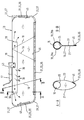
- the airbag module comprises an airbag cover 13 shown in the expanded state and a gas generator 17.
- the airbag cover 13 comprises two material layers 21, 23 which have substantially the same shape and the same size and in a manner explained in more detail below for forming the airbag cover 13 glued together.
- an internal gas distributor 15 or channel which comprises a material layer 25 and is integrated in the airbag envelope 13 or forms part of the airbag envelope 13.
- the layers 21, 23 of the airbag cover 13 on the one hand and the layer 25 of the gas distributor 15 may be made of the same material or of different materials.
- the gas distributor 15 may be a separate component which is connected to the material layers 21, 23 of the airbag envelope in the manufacture of the airbag.
- the gas distributor 15 may be formed by a section of at least one appropriately cut material layer 21, 23 of the airbag envelope 13.
- the gas distributor 15 is tubular and arranged directly on an edge region of the airbag envelope 13, as can be seen in particular from the sectional views AA and BB.
- a kind of pocket 43 is formed outside of the airbag envelope 13, which can be formed by a separate material layer or by at least one suitably cut material layer 21, 23 of the airbag envelope 13.
- the pocket 43 serves to receive a gas generator 17, which protrudes into the gas distributor 15 via the pocket 43.
- the gas generator 17 is formed in this embodiment thrust neutral, ie from the discharge end of the gas generator 17 located inside the gas distributor 15, the gas flows in opposite directions into the gas distributor 15.
- the material layers 21, 23 of the airbag envelope 13 are connected to one another at the upper edge region of the airbag envelope 13 in the figure, that is to say at the edge region where the gas distributor 15 is arranged. This can be done either by any desired connection means or the material layers 21 , 23 may also be integrally connected to each other, ie the airbag cover 13 insofar comprises a single piece of material, which is folded over to form the material layers 21, 23 at the upper edge region.
- the gas distributor 15 is provided with a plurality of gas outlet openings 39 which are arranged so that each of a plurality of chambers 11 of the airbag can be supplied with gas virtually simultaneously.
- three chambers 11 are provided, wherein the left and the right chamber 11 can be filled in each case via one of the one or more gas outlet openings 39 end faces of the gas distributor 15 with gas, while the central chamber 11 with the gas distributor 15 over several Gas outlet openings 39 is in communication, which are formed in the lateral surface of the gas distributor 15.
- a provided between the middle chamber 11 and the right chamber 11 portion of the airbag forms a passive region 41 which is not filled with gas during inflation of the airbag.
- the formation of the chambers 11 in the airbag cover 13 and the airbag cover 13 is done by gluing the respective material layers.
- an edge gluing 31 is provided in the edge region.
- corner regions 37 are the material layers 21, 23rd simply flat to each other and are glued line or strip-shaped together. These areas of the edge bond 31 are therefore subjected to an exfoliating load when loaded, ie during inflation of the airbag and when the airbag is inflated.
- the rectilinear regions 35 of the airbag boundary are formed in another way: a material layer 21 is provided with strip-shaped tabs 45, which are folded over to produce the airbag envelope 13 and folded over the other material layer 23 such that the insides of the tabs 45 are on the outside of the other Laying material layer 23 and can be glued to this.
- the rectilinear portions 35 of the edge bond 31 are thus subjected to a shear stress under load.
- the material layers 21, 23 are connected to each other either by any means, e.g. by gluing and / or sewing, or the material layers 21, 23 form integrally formed portions of a single layer of material, which is used according to the appropriate blank for producing the airbag envelope 13 and folded at the top to the two (sub) layers 21st To form 23.
- the edge adhesive 31 can be subjected to comparatively high loads due to the shear stress configuration provided in the linear regions 35, ie the tightness of the airbag skin 13 is also relative ensures high loads.
- the shape or contour of the expanded airbag envelope 13 can be chosen so that only rectilinear or slightly curved regions 35 are present, with the exception of the corner regions 37, which can be relatively easily brought into a shear stress configuration as explained above.
- the airbag contour whose capacity can be increased accordingly.
- a plurality of line or strip-shaped separating bonds 19 are provided, on which the material layers 21, 23 of the airbag envelope 13 -as in the corner regions 37 -are glued together only one upon the other and are consequently subjected to an exfoliating stress when loaded ,
- the separating bonds 19 extend with the involvement of the gas distributor 15 from edge region to edge region, so that no ends ending within the airbag volume are present and an overflow of gas from chamber 11 to chamber 11 is not possible. Consequently, the gas can only pass through the gas distributor 15 into the chambers 11 and therefore not into the passive region 41 of the airbag envelope 15, which is thus not inflated with it.
- a second section of the release bonds 19 each comprises two subsections 29a, 29b in which one of the material layers 21, 23 of the airbag cover 13 is connected to the material layer 25 of the gas distributor 15.
- the separating bonds 19 thus have a branching on the gas distributor 15, wherein it has been found that the load capacity of the release bonds 19 in the branching area is significantly larger than originally expected.
- the airbag When the release bonds 19 are released due to a load exceeding a certain level without destroying or damaging the material layers, the airbag nevertheless remains gas-tight and thus - but without the original chamber division - Functional in principle, since the edge bond 31 of the load continues to withstand and thus continue a protective gas volume is available. As already mentioned, a controlled yielding of the airbag can hereby be realized by the release bonds 19 being interpreted to a certain extent as "intended separation points".
- the material layers 21, 23 are rounded off in the corner regions 37, so that they substantially follow the course of the edge adhesion 31. Consequently, little material remains outside the edge adhesive 31.
- the corner regions 37 can be made square, as indicated in the figure by the example of the upper right corner by a dashed line.
- the additional material i. the resulting material bag, can be used to connect the air bag in the vehicle, for example, guy lines or other fasteners.
- the airbag is shown here as a so-called center module, in which the inflation by the gas generator 17 in a central region - viewed in a direction from front to back - takes place.
- the airbag can also be a so-called final fill module, in which the gas generator at least slightly away from the air bag at the end of a longitudinally extending along the air bag and provided with gas outlet openings gas line is arranged, for example in the form of a pipe or a tube.
- the airbag may also be provided on its longitudinal side opposite the gas distributor or channel 15, that is to say in the figure on the lower side, with one or more internal channels which allow an overflow of gas from a chamber 11 in an adjacent chamber 11 allows.
- two adjacent chambers 11 are connected to each other by a channel.
- This allows a pressure equalization between the chambers 11.
- Such pressure equalization channels preferably correspond substantially to the gas distributor 15, ie consist of at least one flexible and / or flexible material layer and are in particular formed as a hose.
- the course of the release bonds 19 in the region of the pressure equalization channels then preferably corresponds to the course of the release bonds 19 in the region of the gas distributor 15, ie the release bonds 19 continue to run from edge to edge.
Landscapes
- Engineering & Computer Science (AREA)
- Mechanical Engineering (AREA)
- Air Bags (AREA)
Priority Applications (2)
| Application Number | Priority Date | Filing Date | Title |
|---|---|---|---|
| EP07015275.6A EP2020344B1 (fr) | 2007-08-03 | 2007-08-03 | Poche d'air pour véhicules automobiles |
| PCT/EP2008/005456 WO2009018884A1 (fr) | 2007-08-03 | 2008-07-03 | Airbag fixé par collage pour véhicules à moteur |
Applications Claiming Priority (1)
| Application Number | Priority Date | Filing Date | Title |
|---|---|---|---|
| EP07015275.6A EP2020344B1 (fr) | 2007-08-03 | 2007-08-03 | Poche d'air pour véhicules automobiles |
Publications (2)
| Publication Number | Publication Date |
|---|---|
| EP2020344A1 true EP2020344A1 (fr) | 2009-02-04 |
| EP2020344B1 EP2020344B1 (fr) | 2014-07-16 |
Family
ID=38831303
Family Applications (1)
| Application Number | Title | Priority Date | Filing Date |
|---|---|---|---|
| EP07015275.6A Active EP2020344B1 (fr) | 2007-08-03 | 2007-08-03 | Poche d'air pour véhicules automobiles |
Country Status (2)
| Country | Link |
|---|---|
| EP (1) | EP2020344B1 (fr) |
| WO (1) | WO2009018884A1 (fr) |
Cited By (1)
| Publication number | Priority date | Publication date | Assignee | Title |
|---|---|---|---|---|
| JP2016117466A (ja) * | 2014-12-24 | 2016-06-30 | オートリブ ディベロップメント エービー | カーテンエアバッグ装置 |
Citations (3)
| Publication number | Priority date | Publication date | Assignee | Title |
|---|---|---|---|---|
| DE19939618A1 (de) | 1998-08-20 | 2000-05-18 | Takata Corp | Schutzpolster für den Kopf eines Fahrzeuginsassen |
| US20010019201A1 (en) | 1998-08-20 | 2001-09-06 | Yasushi Masuda | Protective cushion for vehicle occupant's head |
| WO2002000476A1 (fr) | 2000-06-23 | 2002-01-03 | Breed Automotive Technology, Inc. | Systeme de protection d'un passager de vehicule |
Family Cites Families (8)
| Publication number | Priority date | Publication date | Assignee | Title |
|---|---|---|---|---|
| JPH04356249A (ja) * | 1991-05-31 | 1992-12-09 | Achilles Corp | 車輌用エアバック |
| US6355123B1 (en) * | 1998-07-06 | 2002-03-12 | Methode Electronics, Inc. | Roll-over air bag having a reinforced perimeter seal and associated method for producing a flat reinforced seal in a roll-over air bag |
| EP1179454A3 (fr) * | 2000-08-10 | 2003-03-12 | Nihon Plast Co., Ltd. | Pièces de coussin de sécurité superposées, assemblées à l'aide de silicones |
| JP2003072505A (ja) * | 2001-08-30 | 2003-03-12 | Takata Corp | 自動車乗員頭部の保護バッグ |
| JP2003072500A (ja) * | 2001-09-07 | 2003-03-12 | Takata Corp | 自動車乗員頭部の保護バッグ |
| JP4380525B2 (ja) * | 2004-12-20 | 2009-12-09 | 豊田合成株式会社 | 頭部保護エアバッグ |
| DE202005001182U1 (de) * | 2005-01-25 | 2005-06-09 | Trw Automotive Safety Systems Gmbh | Gassack einer Rückhalteeinrichtung |
| DE102005021371A1 (de) * | 2005-05-04 | 2006-11-23 | Autoliv Development Ab | Gassack |
-
2007
- 2007-08-03 EP EP07015275.6A patent/EP2020344B1/fr active Active
-
2008
- 2008-07-03 WO PCT/EP2008/005456 patent/WO2009018884A1/fr not_active Ceased
Patent Citations (3)
| Publication number | Priority date | Publication date | Assignee | Title |
|---|---|---|---|---|
| DE19939618A1 (de) | 1998-08-20 | 2000-05-18 | Takata Corp | Schutzpolster für den Kopf eines Fahrzeuginsassen |
| US20010019201A1 (en) | 1998-08-20 | 2001-09-06 | Yasushi Masuda | Protective cushion for vehicle occupant's head |
| WO2002000476A1 (fr) | 2000-06-23 | 2002-01-03 | Breed Automotive Technology, Inc. | Systeme de protection d'un passager de vehicule |
Cited By (1)
| Publication number | Priority date | Publication date | Assignee | Title |
|---|---|---|---|---|
| JP2016117466A (ja) * | 2014-12-24 | 2016-06-30 | オートリブ ディベロップメント エービー | カーテンエアバッグ装置 |
Also Published As
| Publication number | Publication date |
|---|---|
| WO2009018884A1 (fr) | 2009-02-12 |
| EP2020344B1 (fr) | 2014-07-16 |
Similar Documents
| Publication | Publication Date | Title |
|---|---|---|
| EP0974498B1 (fr) | Système de retenue à sac de sécurité gonflable | |
| EP2203331B1 (fr) | Système d'airbag pour protéger un occupant d'un véhicule | |
| EP3956181B1 (fr) | Sac gonflable tissé en une seule pièce | |
| DE60001058T2 (de) | Aufblasbarer luftsack | |
| EP2222517B1 (fr) | Sac gonflable pourvu d'une tubulure de remplissage et dispositif comprenant un sac gonflable et un générateur de gaz | |
| EP0881130A2 (fr) | Sac gonflable pour un système de retenue d'un passager dans un véhicule | |
| WO2008142142A2 (fr) | Répartiteur de flux gazeux pour un module sac gonflable | |
| DE102014212238A1 (de) | Gassack für ein Fahrzeuginsassen-Rückhaltesystem und Verfahren zum Falten eines Gassacks für ein Fahrzeuginsassen-Rückhaltesystem | |
| DE2221260A1 (de) | Vorrichtung zur Verhinderung von Reifenpannen | |
| DE10361372A1 (de) | Aufblasbarer Vorhang | |
| EP0936981A1 (fr) | Sac a gaz pour un module airbag, et procede et dispositif de pliage d'un sac a gaz | |
| DE102010040119B4 (de) | Gassack für ein Personen-Schutzsystem eines Fahrzeugs und Verfahren zu dessen Herstellung | |
| DE102019109901B4 (de) | Gassack für eine Gassackeinheit zum Schutz eines Knie-/Unterschenkelbereiches und Verfahren zum Herstellen eines Gassacks | |
| EP2389304B1 (fr) | Sac gonflable pour un système de retenue des passagers d'un véhicule et procédé de production d'une sac gonflable | |
| EP2020344B1 (fr) | Poche d'air pour véhicules automobiles | |
| DE102008036353A1 (de) | Gassackeinrichtung | |
| WO2011073445A1 (fr) | Coussin à gaz pour un système de protection de personnes d'un véhicule et procédé pour sa fabrication | |
| EP2939583B1 (fr) | Procédé et dispositif de production d'un sac d'aspirateur et sac d'aspirateur | |
| EP2032399B1 (fr) | Coussin gonflable ainsi que procédé de fabrication d'un coussin gonflable | |
| DE102005055135B4 (de) | Gassack für eine Insassenrückhalteeinrichtung und Verfahren zur Herstellung eines Gassackes für eine Insassenrückhalteeinrichtung | |
| DE10220364A1 (de) | Sicherheitseinrichtung | |
| WO2013131954A1 (fr) | Système de coussin de sécurité gonflable pour véhicule automobile et procédé de fabrication d'un système de coussin de sécurité gonflable | |
| WO2012131002A1 (fr) | Coussin gonflable pour un système de protection de personne d'un véhicule et son procédé de fabrication | |
| EP2033852A1 (fr) | Guidage de gaz | |
| DE102022129962A1 (de) | Airbag und verfahren zum packen eines airbags |
Legal Events
| Date | Code | Title | Description |
|---|---|---|---|
| PUAI | Public reference made under article 153(3) epc to a published international application that has entered the european phase |
Free format text: ORIGINAL CODE: 0009012 |
|
| 17P | Request for examination filed |
Effective date: 20080528 |
|
| AK | Designated contracting states |
Kind code of ref document: A1 Designated state(s): AT BE BG CH CY CZ DE DK EE ES FI FR GB GR HU IE IS IT LI LT LU LV MC MT NL PL PT RO SE SI SK TR |
|
| AX | Request for extension of the european patent |
Extension state: AL BA HR MK RS |
|
| 17Q | First examination report despatched |
Effective date: 20090703 |
|
| AKX | Designation fees paid |
Designated state(s): AT BE BG CH CY CZ DE DK EE ES FI FR GB GR HU IE IS IT LI LT LU LV MC MT NL PL PT RO SE SI SK TR |
|
| RAP1 | Party data changed (applicant data changed or rights of an application transferred) |
Owner name: AUTOLIV DEVELOPMENT AB |
|
| REG | Reference to a national code |
Ref country code: DE Ref legal event code: R079 Ref document number: 502007013280 Country of ref document: DE Free format text: PREVIOUS MAIN CLASS: B60R0021233000 Ipc: B60R0021232000 |
|
| RIC1 | Information provided on ipc code assigned before grant |
Ipc: B60R 21/2346 20110101ALI20130819BHEP Ipc: B60R 21/232 20110101AFI20130819BHEP Ipc: B60R 21/233 20060101ALI20130819BHEP Ipc: B60R 21/235 20060101ALI20130819BHEP Ipc: B60R 21/2342 20110101ALI20130819BHEP |
|
| GRAP | Despatch of communication of intention to grant a patent |
Free format text: ORIGINAL CODE: EPIDOSNIGR1 |
|
| INTG | Intention to grant announced |
Effective date: 20131023 |
|
| GRAP | Despatch of communication of intention to grant a patent |
Free format text: ORIGINAL CODE: EPIDOSNIGR1 |
|
| GRAS | Grant fee paid |
Free format text: ORIGINAL CODE: EPIDOSNIGR3 |
|
| GRAA | (expected) grant |
Free format text: ORIGINAL CODE: 0009210 |
|
| INTG | Intention to grant announced |
Effective date: 20140519 |
|
| AK | Designated contracting states |
Kind code of ref document: B1 Designated state(s): AT BE BG CH CY CZ DE DK EE ES FI FR GB GR HU IE IS IT LI LT LU LV MC MT NL PL PT RO SE SI SK TR |
|
| REG | Reference to a national code |
Ref country code: GB Ref legal event code: FG4D Free format text: NOT ENGLISH |
|
| REG | Reference to a national code |
Ref country code: CH Ref legal event code: EP |
|
| REG | Reference to a national code |
Ref country code: IE Ref legal event code: FG4D Free format text: LANGUAGE OF EP DOCUMENT: GERMAN |
|
| REG | Reference to a national code |
Ref country code: AT Ref legal event code: REF Ref document number: 677410 Country of ref document: AT Kind code of ref document: T Effective date: 20140815 |
|
| REG | Reference to a national code |
Ref country code: DE Ref legal event code: R096 Ref document number: 502007013280 Country of ref document: DE Effective date: 20140828 |
|
| REG | Reference to a national code |
Ref country code: NL Ref legal event code: VDEP Effective date: 20140716 |
|
| REG | Reference to a national code |
Ref country code: LT Ref legal event code: MG4D |
|
| PG25 | Lapsed in a contracting state [announced via postgrant information from national office to epo] |
Ref country code: PT Free format text: LAPSE BECAUSE OF FAILURE TO SUBMIT A TRANSLATION OF THE DESCRIPTION OR TO PAY THE FEE WITHIN THE PRESCRIBED TIME-LIMIT Effective date: 20141117 Ref country code: GR Free format text: LAPSE BECAUSE OF FAILURE TO SUBMIT A TRANSLATION OF THE DESCRIPTION OR TO PAY THE FEE WITHIN THE PRESCRIBED TIME-LIMIT Effective date: 20141017 Ref country code: BG Free format text: LAPSE BECAUSE OF FAILURE TO SUBMIT A TRANSLATION OF THE DESCRIPTION OR TO PAY THE FEE WITHIN THE PRESCRIBED TIME-LIMIT Effective date: 20141016 Ref country code: ES Free format text: LAPSE BECAUSE OF FAILURE TO SUBMIT A TRANSLATION OF THE DESCRIPTION OR TO PAY THE FEE WITHIN THE PRESCRIBED TIME-LIMIT Effective date: 20140716 Ref country code: FI Free format text: LAPSE BECAUSE OF FAILURE TO SUBMIT A TRANSLATION OF THE DESCRIPTION OR TO PAY THE FEE WITHIN THE PRESCRIBED TIME-LIMIT Effective date: 20140716 Ref country code: SE Free format text: LAPSE BECAUSE OF FAILURE TO SUBMIT A TRANSLATION OF THE DESCRIPTION OR TO PAY THE FEE WITHIN THE PRESCRIBED TIME-LIMIT Effective date: 20140716 Ref country code: LT Free format text: LAPSE BECAUSE OF FAILURE TO SUBMIT A TRANSLATION OF THE DESCRIPTION OR TO PAY THE FEE WITHIN THE PRESCRIBED TIME-LIMIT Effective date: 20140716 |
|
| PG25 | Lapsed in a contracting state [announced via postgrant information from national office to epo] |
Ref country code: CY Free format text: LAPSE BECAUSE OF FAILURE TO SUBMIT A TRANSLATION OF THE DESCRIPTION OR TO PAY THE FEE WITHIN THE PRESCRIBED TIME-LIMIT Effective date: 20140716 Ref country code: PL Free format text: LAPSE BECAUSE OF FAILURE TO SUBMIT A TRANSLATION OF THE DESCRIPTION OR TO PAY THE FEE WITHIN THE PRESCRIBED TIME-LIMIT Effective date: 20140716 Ref country code: IS Free format text: LAPSE BECAUSE OF FAILURE TO SUBMIT A TRANSLATION OF THE DESCRIPTION OR TO PAY THE FEE WITHIN THE PRESCRIBED TIME-LIMIT Effective date: 20141116 Ref country code: NL Free format text: LAPSE BECAUSE OF FAILURE TO SUBMIT A TRANSLATION OF THE DESCRIPTION OR TO PAY THE FEE WITHIN THE PRESCRIBED TIME-LIMIT Effective date: 20140716 Ref country code: LV Free format text: LAPSE BECAUSE OF FAILURE TO SUBMIT A TRANSLATION OF THE DESCRIPTION OR TO PAY THE FEE WITHIN THE PRESCRIBED TIME-LIMIT Effective date: 20140716 |
|
| REG | Reference to a national code |
Ref country code: CH Ref legal event code: PL |
|
| REG | Reference to a national code |
Ref country code: DE Ref legal event code: R097 Ref document number: 502007013280 Country of ref document: DE |
|
| PG25 | Lapsed in a contracting state [announced via postgrant information from national office to epo] |
Ref country code: DK Free format text: LAPSE BECAUSE OF FAILURE TO SUBMIT A TRANSLATION OF THE DESCRIPTION OR TO PAY THE FEE WITHIN THE PRESCRIBED TIME-LIMIT Effective date: 20140716 Ref country code: MC Free format text: LAPSE BECAUSE OF FAILURE TO SUBMIT A TRANSLATION OF THE DESCRIPTION OR TO PAY THE FEE WITHIN THE PRESCRIBED TIME-LIMIT Effective date: 20140716 Ref country code: RO Free format text: LAPSE BECAUSE OF FAILURE TO SUBMIT A TRANSLATION OF THE DESCRIPTION OR TO PAY THE FEE WITHIN THE PRESCRIBED TIME-LIMIT Effective date: 20140716 Ref country code: LI Free format text: LAPSE BECAUSE OF NON-PAYMENT OF DUE FEES Effective date: 20140831 Ref country code: EE Free format text: LAPSE BECAUSE OF FAILURE TO SUBMIT A TRANSLATION OF THE DESCRIPTION OR TO PAY THE FEE WITHIN THE PRESCRIBED TIME-LIMIT Effective date: 20140716 Ref country code: BE Free format text: LAPSE BECAUSE OF NON-PAYMENT OF DUE FEES Effective date: 20140831 Ref country code: SK Free format text: LAPSE BECAUSE OF FAILURE TO SUBMIT A TRANSLATION OF THE DESCRIPTION OR TO PAY THE FEE WITHIN THE PRESCRIBED TIME-LIMIT Effective date: 20140716 Ref country code: IT Free format text: LAPSE BECAUSE OF FAILURE TO SUBMIT A TRANSLATION OF THE DESCRIPTION OR TO PAY THE FEE WITHIN THE PRESCRIBED TIME-LIMIT Effective date: 20140716 Ref country code: CZ Free format text: LAPSE BECAUSE OF FAILURE TO SUBMIT A TRANSLATION OF THE DESCRIPTION OR TO PAY THE FEE WITHIN THE PRESCRIBED TIME-LIMIT Effective date: 20140716 Ref country code: CH Free format text: LAPSE BECAUSE OF NON-PAYMENT OF DUE FEES Effective date: 20140831 |
|
| REG | Reference to a national code |
Ref country code: IE Ref legal event code: MM4A |
|
| PLBE | No opposition filed within time limit |
Free format text: ORIGINAL CODE: 0009261 |
|
| STAA | Information on the status of an ep patent application or granted ep patent |
Free format text: STATUS: NO OPPOSITION FILED WITHIN TIME LIMIT |
|
| 26N | No opposition filed |
Effective date: 20150417 |
|
| GBPC | Gb: european patent ceased through non-payment of renewal fee |
Effective date: 20141016 |
|
| PG25 | Lapsed in a contracting state [announced via postgrant information from national office to epo] |
Ref country code: GB Free format text: LAPSE BECAUSE OF NON-PAYMENT OF DUE FEES Effective date: 20141016 |
|
| PG25 | Lapsed in a contracting state [announced via postgrant information from national office to epo] |
Ref country code: IE Free format text: LAPSE BECAUSE OF NON-PAYMENT OF DUE FEES Effective date: 20140803 |
|
| REG | Reference to a national code |
Ref country code: AT Ref legal event code: MM01 Ref document number: 677410 Country of ref document: AT Kind code of ref document: T Effective date: 20140803 |
|
| PG25 | Lapsed in a contracting state [announced via postgrant information from national office to epo] |
Ref country code: AT Free format text: LAPSE BECAUSE OF NON-PAYMENT OF DUE FEES Effective date: 20140803 Ref country code: SI Free format text: LAPSE BECAUSE OF FAILURE TO SUBMIT A TRANSLATION OF THE DESCRIPTION OR TO PAY THE FEE WITHIN THE PRESCRIBED TIME-LIMIT Effective date: 20140716 |
|
| PG25 | Lapsed in a contracting state [announced via postgrant information from national office to epo] |
Ref country code: MT Free format text: LAPSE BECAUSE OF FAILURE TO SUBMIT A TRANSLATION OF THE DESCRIPTION OR TO PAY THE FEE WITHIN THE PRESCRIBED TIME-LIMIT Effective date: 20140716 |
|
| PG25 | Lapsed in a contracting state [announced via postgrant information from national office to epo] |
Ref country code: LU Free format text: LAPSE BECAUSE OF NON-PAYMENT OF DUE FEES Effective date: 20140803 Ref country code: HU Free format text: LAPSE BECAUSE OF FAILURE TO SUBMIT A TRANSLATION OF THE DESCRIPTION OR TO PAY THE FEE WITHIN THE PRESCRIBED TIME-LIMIT; INVALID AB INITIO Effective date: 20070803 Ref country code: TR Free format text: LAPSE BECAUSE OF FAILURE TO SUBMIT A TRANSLATION OF THE DESCRIPTION OR TO PAY THE FEE WITHIN THE PRESCRIBED TIME-LIMIT Effective date: 20140716 |
|
| REG | Reference to a national code |
Ref country code: FR Ref legal event code: PLFP Year of fee payment: 10 |
|
| REG | Reference to a national code |
Ref country code: FR Ref legal event code: PLFP Year of fee payment: 11 |
|
| REG | Reference to a national code |
Ref country code: FR Ref legal event code: PLFP Year of fee payment: 12 |
|
| PGFP | Annual fee paid to national office [announced via postgrant information from national office to epo] |
Ref country code: FR Payment date: 20190829 Year of fee payment: 13 |
|
| PG25 | Lapsed in a contracting state [announced via postgrant information from national office to epo] |
Ref country code: FR Free format text: LAPSE BECAUSE OF NON-PAYMENT OF DUE FEES Effective date: 20200831 |
|
| PGFP | Annual fee paid to national office [announced via postgrant information from national office to epo] |
Ref country code: DE Payment date: 20250827 Year of fee payment: 19 |