EP2020346A2 - Appareil et procédé pour démarrer un moteur d'automobile à l'aide d'un bouton de démarrage - Google Patents
Appareil et procédé pour démarrer un moteur d'automobile à l'aide d'un bouton de démarrage Download PDFInfo
- Publication number
- EP2020346A2 EP2020346A2 EP08160693A EP08160693A EP2020346A2 EP 2020346 A2 EP2020346 A2 EP 2020346A2 EP 08160693 A EP08160693 A EP 08160693A EP 08160693 A EP08160693 A EP 08160693A EP 2020346 A2 EP2020346 A2 EP 2020346A2
- Authority
- EP
- European Patent Office
- Prior art keywords
- signal
- key fob
- engine
- button
- starting
- Prior art date
- Legal status (The legal status is an assumption and is not a legal conclusion. Google has not performed a legal analysis and makes no representation as to the accuracy of the status listed.)
- Withdrawn
Links
Images





Classifications
-
- F—MECHANICAL ENGINEERING; LIGHTING; HEATING; WEAPONS; BLASTING
- F02—COMBUSTION ENGINES; HOT-GAS OR COMBUSTION-PRODUCT ENGINE PLANTS
- F02N—STARTING OF COMBUSTION ENGINES; STARTING AIDS FOR SUCH ENGINES, NOT OTHERWISE PROVIDED FOR
- F02N11/00—Starting of engines by means of electric motors
- F02N11/08—Circuits specially adapted for starting of engines
-
- B—PERFORMING OPERATIONS; TRANSPORTING
- B60—VEHICLES IN GENERAL
- B60R—VEHICLES, VEHICLE FITTINGS, OR VEHICLE PARTS, NOT OTHERWISE PROVIDED FOR
- B60R25/00—Fittings or systems for preventing or indicating unauthorised use or theft of vehicles
- B60R25/20—Means to switch the anti-theft system on or off
- B60R25/2063—Ignition switch geometry
-
- B—PERFORMING OPERATIONS; TRANSPORTING
- B60—VEHICLES IN GENERAL
- B60R—VEHICLES, VEHICLE FITTINGS, OR VEHICLE PARTS, NOT OTHERWISE PROVIDED FOR
- B60R25/00—Fittings or systems for preventing or indicating unauthorised use or theft of vehicles
- B60R25/01—Fittings or systems for preventing or indicating unauthorised use or theft of vehicles operating on vehicle systems or fittings, e.g. on doors, seats or windscreens
- B60R25/04—Fittings or systems for preventing or indicating unauthorised use or theft of vehicles operating on vehicle systems or fittings, e.g. on doors, seats or windscreens operating on the propulsion system, e.g. engine or drive motor
- B60R25/045—Fittings or systems for preventing or indicating unauthorised use or theft of vehicles operating on vehicle systems or fittings, e.g. on doors, seats or windscreens operating on the propulsion system, e.g. engine or drive motor by limiting or cutting the electrical supply to the propulsion unit
-
- B—PERFORMING OPERATIONS; TRANSPORTING
- B60—VEHICLES IN GENERAL
- B60R—VEHICLES, VEHICLE FITTINGS, OR VEHICLE PARTS, NOT OTHERWISE PROVIDED FOR
- B60R25/00—Fittings or systems for preventing or indicating unauthorised use or theft of vehicles
- B60R25/20—Means to switch the anti-theft system on or off
- B60R25/24—Means to switch the anti-theft system on or off using electronic identifiers containing a code not memorised by the user
-
- F—MECHANICAL ENGINEERING; LIGHTING; HEATING; WEAPONS; BLASTING
- F02—COMBUSTION ENGINES; HOT-GAS OR COMBUSTION-PRODUCT ENGINE PLANTS
- F02N—STARTING OF COMBUSTION ENGINES; STARTING AIDS FOR SUCH ENGINES, NOT OTHERWISE PROVIDED FOR
- F02N11/00—Starting of engines by means of electric motors
- F02N11/10—Safety devices
-
- F—MECHANICAL ENGINEERING; LIGHTING; HEATING; WEAPONS; BLASTING
- F02—COMBUSTION ENGINES; HOT-GAS OR COMBUSTION-PRODUCT ENGINE PLANTS
- F02N—STARTING OF COMBUSTION ENGINES; STARTING AIDS FOR SUCH ENGINES, NOT OTHERWISE PROVIDED FOR
- F02N15/00—Other power-operated starting apparatus; Component parts, details, or accessories, not provided for in, or of interest apart from groups F02N5/00 - F02N13/00
- F02N15/10—Safety devices not otherwise provided for
Definitions
- the present invention relates to an apparatus and a method for starting the engine of an automobile, and more particularly, to an apparatus and a method for starting the engine of an automobile using a start-button, which allow a proper user to start the engine through a simple operation of the start-button for starting the engine without having a car key.
- an ignition lock device for starting the engine of an automobile is also called a start switch for starting the engine and integrated with a locking device of a steering column in order to prevent the automobile from being stolen.
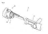
- a conventional ignition lock device 1 of an automobile is fixed to a steering column 3 connected to a steering wheel 2 and includes a key hole 13 into which a car key is inserted by a driver.
- the ignition lock device 1 includes an ignition lock body 11 and a key cylinder 12.
- the ignition lock body 11 is integrated with the steering column 2 and fixed to the steering column 3 and includes the key hole 13 formed at the front side.
- the key cylinder 12 is combined with the inside of the ignition lock body 11 through a combining pin P and rotated with the car key being inserted thereinto such that the car key operates.
- the key cylinder 12 includes the key hole 13 and a cylinder cover 14 for protecting the outer face of the ignition lock body 11.
- the rotating operation of the car key is composed of four steps of a locking step, an accessory power supply step, a controller and driver on step, and a starting step. The car key is inserted into or ejected from the key hole 13 only in the locking step.
- the aforementioned conventional ignition lock device is a mechanical lock device provided near a car door locking unit and the steering column.
- This mechanical lock device operates according to the rotating operation of the car key inserted by a driver to start the engine or cancel a locked state of the steering column.
- the conventional mechanical lock device requires the driver to insert the car key thereinto and rotate the car key. Furthermore, even though the conventional mechanical lock device is damaged, the engine can be started through a simple operation. Accordingly, the automobile having the mechanical lock device is easily stolen.
- a smart key is provided to some of recent automobiles on the market.
- the car using the smart key has a key cylinder and a steering column in modified structures such that the car key cannot be inserted into the key cylinder when normal authentication is not performed.
- a user can lock/unlock the doors of the car only using the smart key and start the car according to an authentication result without inserting the car key into the key cylinder.
- An apparatus for starting the engine of au automobile using a start-button comprises an ignition lock body, a key cylinder, a start-button, and a controller.
- the ignition lock body is connected to a steering column of the automobile.
- the key cylinder combined with the inside of the ignition lock body is extended into the ignition lock body and includes a motor with a shaft that is connected to the steering column and has a first hole formed at one end thereof and a safety member inserted/separated into/from the first hole.
- the start-button applies a starting signal for starting the engine to the controller.
- the controller receives the starting signal from the start-button, performs authentication on a key FOB of the automobile, separates the safety member from the first hole when the key FOB passes authentication and drives the motor to operate the steering column connected to the shaft so as to start the engine.
- the controller inserts the safety member into the first hole to lock the shaft when the engine is started.
- a method for starting the engine of an automobile using a start-button comprises the steps of determining whether a plurality of signals including the start-button are on, requesting a key FOB to transmit the ID thereof, receiving the ID from the key FOB, and performing authentication on the key FOB using the received ID when the signals are on, providing power to a starting motor and applying a driving signal to a motor driver to drive a motor when the key FOB passes authentication, driving a shaft according to the operation of the motor to operate a steering column and driving the starting motor to start the engine, and inserting a safety member into a first hole of the shaft to block the shaft from moving and rotating when the engine is started.
- the key cylinder and the ignition lock body are integrated with each other, the steering column is operated using the motor provided to the inside of the key cylinder, and a proper user can operate the start-button to easily start the engine without having a car key. Accordingly, it is possible to automatically start the engine only using the start-button without inserting a mechanical car key into the key cylinder.
- the safety member is inserted into a hole formed at the shaft to block the shaft from moving and rotating when the engine is started, and thus the motor is prevented from rotating due to external impact applied to the car and other noise impacts caused by an uneven surface of road.
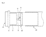
- an apparatus for starting the engine of an automobile includes an ignition lock body 100, a key cylinder 200, a start-button 400, and a controller 300.
- the ignition lock body 100 is connected to a steering column of the automobile.
- the key cylinder 200 is combined with the inside of the ignition lock body 100.
- the key cylinder 200 is extended into the ignition lock body 200 and includes a motor 21 that is connected to the steering column and has a shaft 22 with a first hole 24 formed at one end thereof and a safety member 25 inserted into and separated from the first hole 24.
- the start-button 400 applies a starting signal for starting the engine to the controller 300.
- the controller 300 is a microprocessor that controls the overall operation of the apparatus for starting the engine of the automobile.
- the controller 300 receives the starting signal from the start-button 400 and performs authentication on a key FOB 500 of the automobile.
- the controller 500 separates the safety member 25 from the first hole 24 and drives the motor 21 to operate the steering column connected to the shaft 22 so as to start the engine.
- the controller 300 inserts the safety member 25 into the first hole 24 to lock the shaft 22.
- the ignition lock body 100 can have a hollow cylindrical shape.
- the key cylinder 200 is mechanically combined with the inside of the ignition lock body 100 through a combining member such as a combining pin or bonding.
- the ignition lock body 100 is connected to the steering column connected to a steering wheel of the automobile.
- the key cylinder 200 includes the motor 21 with the shaft 22 and the safety member 25.
- the shaft 22 is connected to the steering column and has the first hole 24 having a predetermined size formed at one end thereof.
- the motor 21 is driven under the control of the controller 300 to move and rotate the shaft 22.
- a driving force according to the moving and rotating operation of the shaft is transmitted to the steering column connected to the shaft 22 to automatically operate the steering wheel and start the engine of the automobile.
- the safety member 25 is inserted into or separated from the first hole 24 formed at one end of the shaft 22 according to a control signal of the controller 300.
- the first hole 23 and the safety member 25 prevents the motor 21 from rotating due to external impact applied to the automobile and other noise impacts caused by an uneven surface of road in an ignition on step after the automobile is started.
- the key cylinder 200 can be integrated with an ignition knob 110 and a coil antenna 23.
- the start-button 400 is connected to the controller 300 and performs a switching function for starting the engine of the automobile.
- a driver pushes the start-button 400, a predetermined authentication process is performed and the motor 21 is driven to move and rotate the shaft 22 so that the engine can be started.
- An automobile has four power mode steps. That is, the power mode of the automobile is changed among lock, accessory power supply, ignition on and start steps according to the rotation of the car key.
- the start-button 400 of the present invention can be used to change the power mode.
- the controller 300 changes the power mode according to the time for which the start-button 400 is pushed and the number of times of pushing the start-button 400. For example, the power mode is changed to accessory power supply state when the start-button 400 is pushed once for shorter than three seconds in lock state and changed to ignition on state when the start-button 400 is pushed twice for shorter than three seconds. The power mode is changed to the ignition on state when the start-button 400 is pushed once in the accessory power supply state. The power mode is change to lock state when the start-button 400 is pushed for longer than three seconds in the accessory power supply state, ignition on state and start state.
- the start-button 400 can be attached to a dash panel at a driver seat such that a driver can use the start-button 400 conveniently.
- the start-button 400 is a switch for easily starting the automobile engine without requiring the driver to inserting a mechanical key into the key hole and rotating the key.
- the starting signal is generated and transmitted to the controller 300.
- the controller 300 performs authentication on the key FOB 500 when the starting signal is applied thereto and transmits a driving signal to the motor 21 to drive the motor 21 when the key FOB 500 passes the authentication.
- the steering column connected to the shaft 22 is driven by the motor 21 to operate the steering wheel and start the engine.
- the controller 300 inserts the safety member 25 into the first hole 24 of the shaft 22 in order to prevent the motor 21 from being operated by disturbance to move and rotate the shaft 22. That is, the shaft is locked in order to block the shaft 22 from moving and rotating for safety after the engine is started.
- the safety member 25 includes a body 26, a mobile 27 moving inside the body 26, a coil 28 partially winding the body 26, and a polarity converter 29 for converting polarity of current flowing through the coil 28.
- the body 26 has a second hole 26a into/from which the mobile 27 is inserted/ejected according to a control signal of the controller 300.
- the coil 28 is wound in a solenoid form such that the coil 28 includes at least the second hole 26a.
- the polarity of both ends of the coil 28 is converted by the polarity converter 29 that operates according to a signal of the controller 300.
- the mobile 27 is formed of metal and, preferably, it is a magnet. When current is applied to this solenoid coil, the coil 28 becomes an electromagnet. When the mobile 27 is inserted into the electromagnet, the mobile 27 moves in the length direction of the solenoid coil according to change of the polarity of the coil 28.
- both ends of the electromagnet have magnetism of S-pole or N-pole according to current applied to the coil 28.
- the polarity is determined by the winding direction of the coil 28 and the direction of current applied to the coil 28. Accordingly, the polarity converter 29 changes the direction of current applied to the coil 28 to convert the polarity of both ends of the coil 28.
- the mobile 27 is moved using this principle such that the mobile is inserted into or ejected from the hole 24 formed at the shaft 22.
- the controller 300 requests the key FOB 500 carried by the driver to transmit its ID and receives the ID through wireless communication with the key FOB 500 when the starting signal is transmitted thereto from the start-button 400.
- the controller 300 performs authentication on the key FOB 500 using the received ID.
- the controller 300 receives various signals with respect to the automobile. That is, the controller 300 receives a key FOB docking signal, a driver seat door closing signal, a bake pedal signal, a gearshift parking signal, a parking brake signal, a run/crank signal, a start completion signal, etc. in addition to the starting signal from the start-button 400.
- the controller 300 receives these signals in order to confirm whether a user who pushes the start-button 400 is a proper user and whether the automobile is in a safe state before the engine is started.
- this precondition for safety is satisfied, authentication of the key FOB 500 is carried out.
- the precondition is an example and can be set in various manners.
- the key FOB 500 has its ID that is used to confirm a proper user of the automobile. Furthermore, the key FOB 500 includes a battery (not shown) so that the key FOB 500 can perform wireless communication with the controller 300 when approaching or entering the automobile. That is, the controller 300 can carry out wireless communication with the key FOB 500 through an antenna set in the inside of the automobile.
- the key FOB 500 can be combined with a docking unit 600.
- the docking unit 600 can be provided to a predetermined portion of the driver seat dash panel such that the key FOB 500 and the docking unit 600 can be combined with each other, as shown in FIG. 5 .
- a push button 601 is pushed to generate the key FOB docking signal and the docking signal is input to the controller 300.
- the controller 300 can recognize that the key FOB 500 is combined with the docking unit 600.
- reference number 603 represents an indication lamp that indicates the battery state of the key FOB 500 combined with the docking unit 600.
- the indication lamp 603 can indicate a satisfactory battery state as blue and indicate a battery state requiring charging as red.
- the controller 300 receives a plurality of external signals and performs a process for starting the automobile engine under a predetermined condition.
- the controller 300 receives the starting signal from the start-button 400 and a plurality of signals representing the state of the automobile and performs authentication on the key FOB 500 through wireless communication with the key FOB 500.
- the controller 300 applies power to the motor 21 to move and rotate the shaft 22 so as to start the engine of the automobile.
- the controller 300 of the apparatus for starting the engine of an automobile includes a wireless transmitter 301, a wireless receiver 302, a micro control unit (MCU) 303, a first relay 304, a second relay 305, and a motor driver 306.
- MCU micro control unit
- the wireless transmitter 301 and the wireless receiver 302 transmit and receive data through wireless communication with the key FOB 500.
- the wireless transmitter 301 transmits a radio signal to the key FOB 500 according to an output signal from the MCU 303 to request the key FOB 500 to transmit the ID thereof.
- the MCU 303 transmits an ID request signal to the key FOB 500 through the wireless transmitter 301 when receiving a start-button on signal S0, a brake pedal signal S3, a gearshift parking signal S4 and a parking brake signal S5.
- the wireless receiver 302 receives the ID from the key FOB 500.
- the wireless transmitter 301 transmits the ID request signal to the key FOB 500 through low frequency (LF) communication.
- the wireless receiver 302 receives the ID from the key FOB 500 through radio frequency (RF) communication.
- LF low frequency
- RF radio frequency
- the MCU 303 includes a signal processor 31 and an authentication unit 32.
- the signal processor 31 receives the start-button on signal S0, a key FOB docking signal S1, a driver seat door closing signal S2, the brake pedal signal S3, the gearshift parking signal S4, the parking brake signal S5, a run/crank signal S6, a start completion signal S7, and a key FOB authentication result signal S8.
- the signal processor 311 transmits a predetermined control signal to the wireless transmitter 301 when the start-button on signal S0, the brake pedal signal S3, the gearshift parking signal S4 and the parking brake signal S5 among the signals S0 to S8 are input thereto.
- the signal receiver transmits the ID request signal to the key FOB 500 through the wireless transmitter 301 and receives the ID of the key FOB 500 through the wireless receiver when the brake pedal signal S3, the gearshift parking signal S4 and the parking brake signal S5 are received after the start-button on signal S0 is received.
- the authentication unit 32 compares the ID of the key FOB 500, received through the wireless receiver 302, with ID stored therein and determines whether the two IDs correspond to each other to authenticate the key FOB 500.
- the signal processor 31 receives the key FOB authentication result signal S8 from the authentication unit 32 and outputs an ON signal to the first relay (A contact) 304 when the key FOB 500 successively passes authentication.
- the signal processor 31 receives and outputs the start completion signal S7 to the second relay (B contact) 305.
- the signal processor 31 outputs an ON signal to the motor driver 306 when the key FOB 500 passes authentication.
- the signal processor 31 outputs a control signal T2 for operating the safety member 25 in order to prevent the shaft 22 from moving and rotating after the engine is started to eliminate the possibility that the motor 21 is driven due to disturbance such as shaking of automobile and an uneven surface of road after engine has been started.
- the first relay 304 receives the run/crank signal S6 and transmits the run/crank signal S6 to a starting motor 20 when the ON signal is output from the signal processor 31. That is, a signal for starting is provided to the starting motor 20.
- the second relay (B contact) 305 applies a signal T1 to the motor driver 306 in the initial stage and its contact is off when the start completion signal S7 is input thereto to block the signal T1 from being input to the motor driver 306. This is for the purpose of blocking the signal T1 applied to the motor driver 306 after the engine is started to prevent the motor driver 306 from operating due to disturbance such as noise of electric signals after the engine is started.
- the motor driver 306 drives the motor 21 when receiving the key FOB authentication result signal S8 representing that the key FOB passes authentication.
- the motor driver 306 drives the motor 21 to move and rotate the shaft 22.
- the steering column operates according to the moving and rotating operation of the shaft 22 and the engine starting signal is transmitted to the starting motor 20 to start the engine.
- the motor driver 306 is driven when the key FOB 500 normally passes authentication while the brake pedal signal S2, the gearshift parking signal S3 and the parking brake signal S4 are input after the starting signal is input from the start-button 400.
- the motor driver 306 drives the motor 21 to move and rotate the shaft 22 such that the steering column combined with the shaft 22 operates to automatically operate the steering wheel and start the engine. Accordingly, the automobile engine can be automatically started without having an additional driver's operation.
- the signal processor 31 outputs a signal T3 for operating the coil antenna 23 included in the ignition lock device if required. By doing so, a voltage is induced to the coil antenna 23 to supply power to the battery of the key FOB 500.
- the apparatus for starting the engine of an automobile can further include the coil antenna 23 for supplying power to the battery of the key FOB 500.
- the controller 300 can apply a driving signal to the coil antenna 23.
- the coil antenna 23 is used when the batteries of the apparatus for starting the engine of an automobile and the key FOB 500 have insufficient power.
- the coil antenna 23 can also be used for an immobilizer function of the automobile.
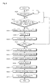
- FIG. 8 is a flow chart of the method for starting the engine of an automobile according to an embodiment of the present invention.
- the controller 300 determines whether the start-button 400 for starting the engine of the automobile is pushed in operation S800.
- the controller 300 waits in the initial state.
- the controller 300 determines whether the brake pedal signal S3, the gearshift parking signal S4 and the parking brake signal S5 are input in operation S802.
- the controller 300 waits in the initial state. When it is determined that the three signals are input in operation S802, the controller 300 requests the key FOB 500 to transmit the ID thereof in operation S804 and receives the ID from the key FOB 500 in operation S806.
- the controller 300 compares the received ID with previously stored ID and performs authentication on the key FOB 500 in operation S808.
- the controller 300 turns on the first relay 304 in operation S812 to provide power to the starting motor 20 in operation S814.
- the controller 300 applies a signal to the motor driver 306 in operation S816.
- the motor driver 306 is operated to drive the motor 21 in operation S818.
- the motor 21 moves and rotates the shaft 22 in operation S820.
- the steering column is operated according to the moving and rotating operation of the shaft 22 in operation S822 and an engine starting signal is transmitted to the starting motor 20 to start the engine in operation S824.
- the engine starting signal is applied to the starting motor 20 to start the engine according to the moving and rotating operation of the shaft 22.
- Power is applied to the motor driver 306 in the initial stage in operation S900 and the controller 300 determines whether the engine start completion signal S7 is input in operation S902.
- the controller 300 waits in the initial state.
- the controller 300 turns off the second relay 305 in operation S904. Since the second relay is a B-contact relay, the contact of the second relay 305 is on in the initial stage and it is off when the engine start completion signal is input.
- the second relay 305 is off in operation S904, and thus the power applied to the motor driver 306 is blocked in operation S906. This operation is performed in order to prevent the motor driver 306 from being operated by predetermined disturbance after the engine is started.
- an apparatus and a method for starting the engine of an automobile using a start-button which allow a proper user to start the engine through a simple operation of the start-button for starting the engine without having a car key.
- a key FOB is requested to transmit its ID, the ID is received from the key FOB, and authentication is performed on the key FOB using the received ID when the signals are on.
- Power is provided to a starting motor and a driving signal is applied to a motor driver to drive a motor when the key FOB passes authentication.
- a shaft is driven according to the operation of the motor to operate a steering column and the starting motor is driven to start the engine.
- a safety member is inserted into a first hole of the shaft to block the shaft from moving and rotating when the engine is started.
Landscapes
- Engineering & Computer Science (AREA)
- Mechanical Engineering (AREA)
- Chemical & Material Sciences (AREA)
- Combustion & Propulsion (AREA)
- General Engineering & Computer Science (AREA)
- Lock And Its Accessories (AREA)
- Output Control And Ontrol Of Special Type Engine (AREA)
Applications Claiming Priority (1)
| Application Number | Priority Date | Filing Date | Title |
|---|---|---|---|
| KR20070076373A KR100916343B1 (ko) | 2007-07-30 | 2007-07-30 | 시동버튼을 이용한 자동차 엔진 시동장치 및 방법 |
Publications (2)
| Publication Number | Publication Date |
|---|---|
| EP2020346A2 true EP2020346A2 (fr) | 2009-02-04 |
| EP2020346A3 EP2020346A3 (fr) | 2012-06-27 |
Family
ID=39967206
Family Applications (1)
| Application Number | Title | Priority Date | Filing Date |
|---|---|---|---|
| EP20080160693 Withdrawn EP2020346A3 (fr) | 2007-07-30 | 2008-07-18 | Appareil et procédé pour démarrer un moteur d'automobile à l'aide d'un bouton de démarrage |
Country Status (5)
| Country | Link |
|---|---|
| US (1) | US20090033150A1 (fr) |
| EP (1) | EP2020346A3 (fr) |
| JP (1) | JP2009029408A (fr) |
| KR (1) | KR100916343B1 (fr) |
| CN (1) | CN101357624B (fr) |
Cited By (1)
| Publication number | Priority date | Publication date | Assignee | Title |
|---|---|---|---|---|
| EP3293706A1 (fr) * | 2016-09-09 | 2018-03-14 | Hyundai Motor Company | Appareil et procédé de recherche de clé intelligente |
Families Citing this family (13)
| Publication number | Priority date | Publication date | Assignee | Title |
|---|---|---|---|---|
| KR100820859B1 (ko) * | 2007-07-31 | 2008-04-11 | 양재우 | 차량 보안을 위한 전자 키 구조 |
| TWI469887B (zh) * | 2009-03-27 | 2015-01-21 | Kamol Kantajaraniti | 變速桿鎖定裝置 |
| US9079494B2 (en) * | 2010-07-01 | 2015-07-14 | Mill Mountain Capital, LLC | Systems, devices and methods for vehicles |
| US9283931B2 (en) * | 2011-12-12 | 2016-03-15 | Mill Mountain Capital, LLC | Systems, devices and methods for vehicles |
| US10194017B2 (en) * | 2011-12-12 | 2019-01-29 | Mill Mountain Capital, LLC | Systems, devices and methods for vehicles |
| JP2014021710A (ja) * | 2012-07-18 | 2014-02-03 | Tokai Rika Co Ltd | ロック装置 |
| US8841987B1 (en) * | 2013-11-22 | 2014-09-23 | Local Motion, Inc. | Upgrade kit for an ignition key and methods |
| US9272688B2 (en) * | 2014-04-04 | 2016-03-01 | Ford Global Technologies, Llc | Method and system for selecting vehicle performance |
| US9865413B2 (en) * | 2015-04-10 | 2018-01-09 | Honda Motor Co., Ltd. | Vehicle control device |
| SE538924C2 (en) * | 2015-06-25 | 2017-02-21 | Scania Cv Ab | Start/stopp switch system, primarily intended for a vehicle |
| JP6851044B2 (ja) * | 2016-12-22 | 2021-03-31 | 朝日電装株式会社 | エンジン始動装置 |
| EP3339110B1 (fr) * | 2016-12-22 | 2020-02-05 | Asahi Denso Co., Ltd. | Dispositif de démarrage de moteur |
| CN109177919B (zh) * | 2018-09-29 | 2022-03-18 | 株式会社电装 | 车辆防盗控制系统及车辆防盗控制方法 |
Family Cites Families (29)
| Publication number | Priority date | Publication date | Assignee | Title |
|---|---|---|---|---|
| US4520640A (en) * | 1981-08-28 | 1985-06-04 | General Motors Corporation | Position control mechanism for a vehicle ignition lock |
| US5036687A (en) * | 1989-07-31 | 1991-08-06 | Nissan Motor Company, Limited | Automotive steering lock system with portable radio code signal transmitter |
| US5086288A (en) * | 1990-05-18 | 1992-02-04 | Borroughs Tool & Equipment Corporation | VATS interrogator accessory |
| JP2842951B2 (ja) * | 1991-03-29 | 1999-01-06 | 日産自動車株式会社 | 自動変速機のキーインターロック装置 |
| US5252861A (en) * | 1991-07-18 | 1993-10-12 | Eaton Corporation | Starter interlock for electronically controlled vehicle |
| US5445575A (en) * | 1994-05-02 | 1995-08-29 | Sundeen; Arthur R. | Ignition lock cylinder and gear shift lever interlock |
| US5497093A (en) * | 1994-05-02 | 1996-03-05 | General Motors Corporation | Method and apparatus for diagnosing a twin-coil, bi-stable, magnetically latched solenoid |
| JP3580923B2 (ja) * | 1995-12-21 | 2004-10-27 | 株式会社日本自動車部品総合研究所 | 盗難防止装置 |
| FR2743762B1 (fr) * | 1996-01-19 | 1998-03-20 | Peugeot | Vehicule automobile a boite de vitesses equipe d'une logique de commande a fonction de verrouillage du levier de vitesses en position parking et fonction de verrouillage de la clef de contact |
| JPH10140900A (ja) * | 1996-09-13 | 1998-05-26 | Tokai Rika Co Ltd | イモビライザシステム塔載車両、及びイモビライザシステムに使用される部材 |
| US6125671A (en) * | 1996-11-13 | 2000-10-03 | Kabushiki Kaisha Tokai Rika Denki Seisakusho | Steering lock system |
| US5977655A (en) * | 1997-02-21 | 1999-11-02 | Honda Giken Kogyo Kabushiki Kaisha | Lock actuator assembly for a steering lock and ignition system |
| AU7628398A (en) * | 1997-09-12 | 1999-03-25 | Robert Bosch Gmbh | An ignition lock system |
| JP3372228B2 (ja) * | 1999-09-29 | 2003-01-27 | 本田技研工業株式会社 | 車両用電子キー装置 |
| AU723285B1 (en) * | 1999-12-10 | 2000-08-24 | Robert Bosch Gmbh | Vehicle start system and method |
| JP3671792B2 (ja) * | 2000-01-21 | 2005-07-13 | トヨタ自動車株式会社 | 移動体用盗難防止装置 |
| JP2002234419A (ja) * | 2001-02-09 | 2002-08-20 | Tokai Rika Co Ltd | 電子式ステアリングロック機構 |
| JP3988540B2 (ja) * | 2002-01-11 | 2007-10-10 | 株式会社デンソー | 車両用エンジン制御装置、車両用イグニッションスイッチ装置、車両用エンジン制御システム、携帯機 |
| KR20030096944A (ko) * | 2002-06-18 | 2003-12-31 | 현대자동차주식회사 | 차량의 도난 방지 시스템 |
| US6873247B2 (en) * | 2002-10-25 | 2005-03-29 | Lear Corporation | Combined vehicle immobilizing and steering column control system |
| JP4217520B2 (ja) * | 2003-04-16 | 2009-02-04 | 株式会社東海理化電機製作所 | スイッチ装置 |
| JP4705317B2 (ja) * | 2003-04-16 | 2011-06-22 | 株式会社東海理化電機製作所 | スイッチ装置、セキュリティシステム |
| JP4494736B2 (ja) * | 2003-08-08 | 2010-06-30 | 株式会社東海理化電機製作所 | エンジン始動制御装置 |
| JP4156493B2 (ja) * | 2003-11-04 | 2008-09-24 | 株式会社東海理化電機製作所 | 車両用セキュリティ装置及びidコード管理装置 |
| JP4428182B2 (ja) * | 2004-09-30 | 2010-03-10 | 株式会社デンソー | エンジン始動制御システム |
| KR100608224B1 (ko) * | 2004-12-31 | 2006-08-08 | 주식회사 에스티에프 | 차량용 개인 식별 제어 시스템 |
| US7401483B2 (en) * | 2005-03-30 | 2008-07-22 | Strattec Security Corporation | Residual magnetic devices and methods for an ignition actuation blockage device |
| DE102005043232A1 (de) * | 2005-09-09 | 2007-03-15 | Bayerische Motoren Werke Ag | Vorrichtung zum Starten des Motors eines Kraftfahrzeugs |
| KR100654556B1 (ko) | 2006-01-11 | 2006-12-05 | 씨멘스 오토모티브 주식회사 | 이모빌라이저 시스템을 이용한 자동차 엔진 시동 방법 및장치 |
-
2007
- 2007-07-30 KR KR20070076373A patent/KR100916343B1/ko active Active
-
2008
- 2008-07-18 JP JP2008187394A patent/JP2009029408A/ja active Pending
- 2008-07-18 EP EP20080160693 patent/EP2020346A3/fr not_active Withdrawn
- 2008-07-22 US US12/177,611 patent/US20090033150A1/en not_active Abandoned
- 2008-07-30 CN CN2008101351156A patent/CN101357624B/zh not_active Expired - Fee Related
Cited By (2)
| Publication number | Priority date | Publication date | Assignee | Title |
|---|---|---|---|---|
| EP3293706A1 (fr) * | 2016-09-09 | 2018-03-14 | Hyundai Motor Company | Appareil et procédé de recherche de clé intelligente |
| CN107804277A (zh) * | 2016-09-09 | 2018-03-16 | 现代自动车株式会社 | 智能钥匙搜索设备和方法 |
Also Published As
| Publication number | Publication date |
|---|---|
| CN101357624A (zh) | 2009-02-04 |
| KR100916343B1 (ko) | 2009-09-11 |
| EP2020346A3 (fr) | 2012-06-27 |
| US20090033150A1 (en) | 2009-02-05 |
| CN101357624B (zh) | 2011-02-02 |
| JP2009029408A (ja) | 2009-02-12 |
| KR20090012492A (ko) | 2009-02-04 |
Similar Documents
| Publication | Publication Date | Title |
|---|---|---|
| US20090033150A1 (en) | Apparatus and method for starting engine of automobile using start-button | |
| EP2020345B1 (fr) | Structure de clé électronique automobile pour plus de sécurité et son procédé pour réaliser cette fonction | |
| JP5570850B2 (ja) | 車両用のスマート通信システムを制御するシステムおよび方法 | |
| US8150563B2 (en) | Anti-theft system for a vehicle, and method for the operation of an anti-theft system | |
| EP2098418B1 (fr) | Dispositif de commande de véhicule | |
| CN109562736B (zh) | 机动车的进入和启动系统和运行方法以及机动车 | |
| US20140200757A1 (en) | Onboard system, electronic key system, and control unit | |
| EP2251837A2 (fr) | Dispositif portable et système de contrôle à distance | |
| JP2012250584A (ja) | 始動制御装置 | |
| US20110208413A1 (en) | Apparatus and method for starting automobile using start-button | |
| JP2004278050A (ja) | パッシブキーレスエントリ装置及び方法 | |
| WO2016157777A1 (fr) | Système de commande de véhicule, dispositif de commande de véhicule et dispositif portable | |
| JP3799961B2 (ja) | 車両用電子キー装置 | |
| KR101480619B1 (ko) | 스마트 키 위치 안내 시스템 | |
| JP2008050943A (ja) | 車両用ワイヤレス制御装置 | |
| KR100820318B1 (ko) | 자동차의 이그니션 노브 록 장치 및 그 록킹방법 | |
| KR100856809B1 (ko) | 무선제어형 이그니션 노브 록 장치 및 그의 록킹방법 | |
| KR100856580B1 (ko) | 전동제어형 자동차 이그니션 노브 록 장치 및 그의록킹방법 | |
| JP4815370B2 (ja) | 車両用エンジン始動システム | |
| JPH1053109A (ja) | 遠隔式車両電装制御装置 | |
| JP6629680B2 (ja) | 車両制御システム、車両制御装置、携帯機 | |
| JP5172623B2 (ja) | キー収容装置 | |
| JP4384946B2 (ja) | パッシブキーレスエントリー装置 | |
| JP4852343B2 (ja) | キーオペレーションシステム | |
| JP2001336328A (ja) | 自動車用キーレスエントリー装置 |
Legal Events
| Date | Code | Title | Description |
|---|---|---|---|
| PUAI | Public reference made under article 153(3) epc to a published international application that has entered the european phase |
Free format text: ORIGINAL CODE: 0009012 |
|
| 17P | Request for examination filed |
Effective date: 20080718 |
|
| AK | Designated contracting states |
Kind code of ref document: A2 Designated state(s): AT BE BG CH CY CZ DE DK EE ES FI FR GB GR HR HU IE IS IT LI LT LU LV MC MT NL NO PL PT RO SE SI SK TR |
|
| AX | Request for extension of the european patent |
Extension state: AL BA MK RS |
|
| RIN1 | Information on inventor provided before grant (corrected) |
Inventor name: KIM, MIN SEOK Inventor name: LEE, KYOUNG MOON Inventor name: KIM, YOUNG TAK Inventor name: KO, JAE PYUNG Inventor name: YANG, JAE WOO |
|
| RAP1 | Party data changed (applicant data changed or rights of an application transferred) |
Owner name: DONG-A UNIVERSITY RESEARCH FOUNDATION FOR INDUSTRY |
|
| PUAL | Search report despatched |
Free format text: ORIGINAL CODE: 0009013 |
|
| AK | Designated contracting states |
Kind code of ref document: A3 Designated state(s): AT BE BG CH CY CZ DE DK EE ES FI FR GB GR HR HU IE IS IT LI LT LU LV MC MT NL NO PL PT RO SE SI SK TR |
|
| AX | Request for extension of the european patent |
Extension state: AL BA MK RS |
|
| RIC1 | Information provided on ipc code assigned before grant |
Ipc: B60R 25/04 20060101ALI20120523BHEP Ipc: B60R 25/02 20060101AFI20120523BHEP |
|
| AKX | Designation fees paid |
Designated state(s): AT BE BG CH CY CZ DE DK EE ES FI FR GB GR HR HU IE IS IT LI LT LU LV MC MT NL NO PL PT RO SE SI SK TR |
|
| STAA | Information on the status of an ep patent application or granted ep patent |
Free format text: STATUS: THE APPLICATION IS DEEMED TO BE WITHDRAWN |
|
| 18D | Application deemed to be withdrawn |
Effective date: 20130103 |