EP2020358B1 - Chariot élévateur doté de bras de charge - Google Patents
Chariot élévateur doté de bras de charge Download PDFInfo
- Publication number
- EP2020358B1 EP2020358B1 EP08009973.2A EP08009973A EP2020358B1 EP 2020358 B1 EP2020358 B1 EP 2020358B1 EP 08009973 A EP08009973 A EP 08009973A EP 2020358 B1 EP2020358 B1 EP 2020358B1
- Authority
- EP
- European Patent Office
- Prior art keywords
- load
- load roller
- rollers
- roller carrier
- lift truck
- Prior art date
- Legal status (The legal status is an assumption and is not a legal conclusion. Google has not performed a legal analysis and makes no representation as to the accuracy of the status listed.)
- Active
Links
Images





Classifications
-
- B—PERFORMING OPERATIONS; TRANSPORTING
- B62—LAND VEHICLES FOR TRAVELLING OTHERWISE THAN ON RAILS
- B62B—HAND-PROPELLED VEHICLES, e.g. HAND CARTS OR PERAMBULATORS; SLEDGES
- B62B3/00—Hand carts having more than one axis carrying transport wheels; Steering devices therefor; Equipment therefor
- B62B3/04—Hand carts having more than one axis carrying transport wheels; Steering devices therefor; Equipment therefor involving means for grappling or securing in place objects to be carried; Loading or unloading equipment
- B62B3/06—Hand carts having more than one axis carrying transport wheels; Steering devices therefor; Equipment therefor involving means for grappling or securing in place objects to be carried; Loading or unloading equipment for simply clearing the load from the ground
- B62B3/0612—Hand carts having more than one axis carrying transport wheels; Steering devices therefor; Equipment therefor involving means for grappling or securing in place objects to be carried; Loading or unloading equipment for simply clearing the load from the ground power operated
-
- B—PERFORMING OPERATIONS; TRANSPORTING
- B62—LAND VEHICLES FOR TRAVELLING OTHERWISE THAN ON RAILS
- B62B—HAND-PROPELLED VEHICLES, e.g. HAND CARTS OR PERAMBULATORS; SLEDGES
- B62B5/00—Accessories or details specially adapted for hand carts
- B62B5/02—Accessories or details specially adapted for hand carts providing for travelling up or down a flight of stairs
- B62B5/025—Accessories or details specially adapted for hand carts providing for travelling up or down a flight of stairs with gliding elements, e.g. skids
-
- B—PERFORMING OPERATIONS; TRANSPORTING
- B62—LAND VEHICLES FOR TRAVELLING OTHERWISE THAN ON RAILS
- B62B—HAND-PROPELLED VEHICLES, e.g. HAND CARTS OR PERAMBULATORS; SLEDGES
- B62B5/00—Accessories or details specially adapted for hand carts
- B62B5/02—Accessories or details specially adapted for hand carts providing for travelling up or down a flight of stairs
- B62B5/026—Accessories or details specially adapted for hand carts providing for travelling up or down a flight of stairs with spiders or adapted wheels
Definitions
- the invention relates to a pallet truck, in particular low-lift truck, with a drive part and a relative to the drive part vertically movable load part having load arms, which are supported by means of at least two load rollers having load roller device on a roadway, the load rollers are rotatably mounted in each case a load roller carrier which is rotatably mounted on a pivot arm, wherein the pivot arm for vertical movement of the load arms is arranged relative to the drive part pivotally mounted on the load arm, and wherein the load rollers are arranged laterally offset in the load roller carrier and superimposed in the longitudinal direction.
- a lift truck in which the load arms by means of a respective load roller device having two load rollers, is supported on the road, is from the EP 1 077 169 A1 known.
- the two load rollers are here tandem and thus arranged in the longitudinal direction of the lift truck in a row. This results in a high space requirement of the load roller device in the longitudinal direction, which particularly complicates the retraction of the lift truck in a quer Hopkins pallet, the load rollers must pass over a floor board of the pallet.
- Generic pallet trucks in which a plurality of load rollers in the load roller carriers laterally offset and arranged superimposed in the longitudinal direction, are from the US 2006/232030 A1 and the DE 25 10 586 A1 known.
- the present invention has for its object to provide a pallet truck of the type mentioned available with the larger obstacles can be run over and with the retraction in a transverse standing pallet is facilitated.
- the load rollers in the load roller carrier are arranged laterally offset, thereby allowing to arrange the axes of rotation of the load rollers such that the distance between the axes of rotation of the load rollers is less than the diameter of the load rollers.
- a superposition of the load rollers in the longitudinal direction allows and thus achieved a small space requirement of the load roller device in the longitudinal direction of the lift truck. Due to the small space requirement of the load roller device in the longitudinal direction, the retraction of the lift truck is facilitated in a transverse range and also allows an enlarged pivoting range of the load roller device relative to the pivot arm, so that with the pallet truck according to the invention continue larger obstacles on the road can be safely and easily run over.
- the arcuate contour of the load roller carrier in this case forms a runner, which causes a pivoting of the load roller carrier when driving over larger obstacles of the road, for example, a curb or a curb, whereby the pallet truck according to the invention safely and easily overcome large obstacles and thus can overcome.
- the fillers form deflectors with which jamming of smaller objects lying on the roadway, for example of stones, between the Load rollers and the load carrier are effectively avoided.
- the filler an additional mass generated that allow a smooth running of the load roller devices on the road despite the reduced distance of the axes of rotation of the load rollers and allow improved stability of the lift truck by a low center of gravity, especially on inclines and gradients and laterally inclined roads.
- the contour extends from a region near the ground to a region which is at the bottom, which substantially corresponds to the height of the load rollers.
- the load roller support encloses the load rollers in both directions of travel, wherein the load roller carrier is provided for each direction of travel, each with an upwardly extending arcuate contour.
- the load carrier is provided for each direction with a runner formed by the contour, which can be overcome safely and easily with the pallet truck according to the invention in both forward drive and in reverse greater obstacles the road.
- At least one stop for limiting the pivoting movement of the load roller carrier relative to the pivot arm is provided on the load roller carrier.
- the stop can be formed with low construction costs according to a preferred embodiment of a arranged on the load roller carrier stop pin, which can be brought into operative connection with the pivot arm
- the additional role is rotatably mounted in the load roller carrier in bodenfemen area in front of the corresponding load roller.
- the additional role which is not in contact with roadway in normal driving and which is located in front of the corresponding load roller at the top of the load roller carrier, the passing of a larger obstacle whose height substantially corresponds to the diameter of the load roller, can be facilitated because the additional role comes into contact with the obstacle and forms an additional climbing aid for the load roller carrier and thus the load roller device in addition to the contour forming the runner.
- the additional role is expediently arranged at the upper end of the arcuate contour on the load roller carrier.
- a climbing aid formed by the additional role can be achieved with low construction costs for both directions.
- the pivot axis of the load roller carrier is arranged centrally in the swivel arm between the axes of rotation of the load rollers.
- the load roller device each have three load rollers, wherein in each load roller carrier three load rollers are arranged in a star shape.
- a star-shaped arrangement of three load rollers can also with the pallet truck according to the invention larger obstacles of the road, for example, a curb or a curb lowering safely and easily run over and thus overcome.
- the load roller carrier with the three star-shaped load rollers is in this case rotatably mounted in the swivel arm 360 °, so that at a larger obstacle whose height corresponds approximately to the diameter of the load rollers, the load roller carrier is pivoted when passing over the obstacle by 120 °, whereby the Override obstacle safely and easily and thus can be overcome.
- a simple construction is achievable in this case when the load roller carrier is provided substantially with a triangular contour, wherein the axes of rotation of the load rollers are arranged as an equilateral triangle. With such an arrangement of the load rollers at the tips of an equilateral triangle, a star-shaped arrangement of the three load rollers can be achieved in a simple manner.
- the axis of rotation of the load roller carrier in the swivel arm in this case according to a preferred embodiment of the invention of the axes of rotation of the load rollers each have the same distance.
- a star-shaped arrangement of the load rollers can be achieved in a simple manner, wherein the load rollers each have an angle of 120 ° with respect to the axis of rotation of the load roller carrier. With such an arrangement of the load rollers larger obstacles in both directions can be overcome in a simple manner.
- the load arms are each designed to be open at the top in the area of the load roller device, a large pivot range of the load roller carriers can be permitted, and thus larger obstacles of the roadway can be overrun in a simple manner.
- FIG. 1 is an inventive, designed as a pallet truck pallet truck 1 with a drive part 2 and a load part 3 shown.
- the drive part 2 comprises a bow-shaped frame portion 2a, on which a traction drive unit 4, which comprises a drive wheel and a driving motor driving the driving wheel, is arranged steerable.
- the steering of the lift truck 1 is effected by means of a drawbar connected to the drive unit 4 4.
- the drive wheel of the drive unit 4 is here designed as a pneumatic tire drive wheel.
- For load part 3 includes two load arms 6a, 6b, with which loads, such as pallets, lattice boxes or small parts container can be added, lifted and transported.
- loads such as pallets, lattice boxes or small parts container
- a vertical strap section 7 is arranged on the load part 3, which is formed by lateral longitudinal braces 7a, 7b, a lower transverse bow 7c and an upper transverse bow 7d.
- the bow-shaped frame section 2a of the drive part 2 and the load part 3 formed by the load arms 6a, 6b and the strap section 7 is essentially formed by one-piece hollow profiles with a closed cross-section.
- the bracket portion 7 serves to receive a housing 8, which is provided with a battery compartment for a battery 8b and in which further electrical or electronic components of an electric drive system of the lift truck 1 are arranged.
- the load part 3 is arranged on the drive part 2 by means of a lever assembly formed by articulated levers 10 movable in the vertical direction.
- a no longer shown, designed for example as a hydraulic cylinder lifting device is provided, which is arranged between the drive part 2 and the load part 3 and generates a force acting on the load part 3 lifting movement.
- the load part 3 is supported by means of each load roller device 9a, 9b on a roadway, which are respectively arranged at the load-side ends of the load arms 6a, 6b. In the area of the load roller device 9a, 9b, the load arms 6a, 6b are open at the top.
- FIGS. 2a and 2b a first embodiment of a load roller device 9a, 9b according to the invention is shown, wherein in the FIG. 2a a side view of the load roller device 9a, 9b is shown and the FIG. 2b a perspective view of the load roller device 9a, 9b shows.
- Each load roller device 9a, 9b has two load rollers 11a, 11b which are arranged one behind the other in the longitudinal direction and which are rotatably mounted in a load roller carrier 12 by means of a respective rotation axis 13a or 13b.
- the load roller carrier 12 is rotatably mounted on a bow-shaped pivot arm 14 by means of a rotation axis 15.
- the axis of rotation 15 is in this case arranged centrally with respect to the axes of rotation 13a, 13b.
- the pivot arm 14 is pivotally mounted on the corresponding load arm 6a and 6b by means of a pivot axis 16.
- On a further axis 17 of the pivot arm 14 is formed, for example, designed as a push rod rod 18 articulated, which is disposed within the load arms 6a, 6b and is in operative connection with the other end to the articulated lever 10.
- a lifting movement of the lifting device can thus be converted by means of the hinge lever 10 and the rods 18 in a pivoting movement of the pivot lever 14 and thus a vertical movement of the load rollers 11 a, 11 b, whereby the load part 3 can be raised or lowered relative to the drive part 2.
- the rods 18 can also be formed here as tie rods.
- the distance between the axes of rotation 13a, 13b of the load rollers 11a, 11b is less than the diameter of the load rollers 11a, 11b, so that the load rollers 11a, 11b - as shown in FIG. 2b is visible - laterally offset in the load roller carrier 12 and arranged superimposed in the longitudinal direction.
- the load roller carrier 12 encloses the load rollers 11a, 11b on the front side and the rear side in the longitudinal direction and is provided with an upwardly extending arcuate contour 20a, 20b on each side and thus for each direction of travel.
- the arcuate contour 20a, 20b extends from a lower region near the bottom to an upper region remote from the bottom, which substantially corresponds to the height of the load rollers 11a, 11b.
- a stop formed by two stop pins 21a, 21b is provided.
- the stop pins 21a, 21b are in this case arranged on a side plate of the load roller carrier 12 and reach during pivoting of the load roller carrier 12 with the pivot arm 14 in operative connection.
- packing 22a, 22b are arranged and fixed, which partially enclose the corresponding load roller 11a, 11b and are adapted to the contour of the load roller carrier 12.
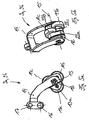
- FIGS. 3a and 3b is a further embodiment of a load roller device according to the invention 9a, 9b shown, which is substantially in the FIGS. 2a, 2b shown load roller device 9a, 9b corresponds.
- the FIG. 3a shows here a view from above and the FIG. 3b a perspective view of the load roller device 9a, 9b.
- the load roller carrier 12 in which the two load rollers 11a, 11b as in the embodiment according to the FIGS. 2a and 2b laterally offset and arranged superimposed in the longitudinal direction is provided with roller-shaped additional rollers 25a, 25b, which are rotatably arranged in the load roller carrier 12 in the area remote from the floor.
- the additional roller 25a is in this case arranged in the upper region of the arcuate contour 20a and is located in the longitudinal direction in front of the load roller 11a.
- the additional roller 25b is located at the top of the arcuate contour 25b and is arranged in the longitudinal direction in front of the load roller 25b.
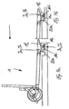
- FIGS. 4a to 4e is one with the load roller devices 9a, 9b according to the FIGS. 2a, 2b or 3a, 3b equipped lifting truck 1 shown when driving over a larger obstacle, such as a curb, which has a height of about 70mm, which substantially corresponds to the diameter of the load rollers 11a, 11b.
- FIGS. 5a to 5d a further embodiment of a load roller device 9a, 9b according to the invention is shown.
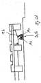
- pivot lever 14 which is pivotally mounted on the axis 16 on the load arm and on which on the axis 17, for example, designed as a push rod rod 18, a load roller support 12 is rotatably mounted about the rotation axis 15 by 360 °, at the three laterally offset and Superposed in the longitudinal direction arranged load rollers 11a, 11b and 11c are arranged in a star shape.
- the load roller 11a is here - as from the FIG. 5c can be seen, in which a plan view of the load roller device 9a, 9b is shown - mounted about a rotational axis 13a in the load roller carrier 12. Accordingly, the load roller 11b is rotatably mounted about a rotation axis 13b and the load roller 13c about a rotation axis 13c, wherein the distance the axes of rotation 13a and 13b between each other is less than the diameter of the load rollers 11a, 11b, 11c and thus the load rollers 11a, 11b and 11c are arranged superimposed. Seen in the longitudinal direction, the axis of rotation 13c is arranged centrally between the axes of rotation 13a and 13b.
- the distance of the rotation axis 13a from the rotation axis 13c is in this case selected such that the rotation axis 13a within the diameter of the load roller 11c and corresponding to the axis of rotation 13c within the diameter of the load roller 11a. Accordingly, the distance between the two rotation axes 13c and 13b is selected such that the axis of rotation 13c within the diameter of the load roller 11b and the axis of rotation 13b is within the diameter of the load roller 11c.
- the load roller 11a is superposed on the load rollers 11b and 11c
- the load roller 11b is superimposed on the load rollers 11a and 11c
- the load roller 11c is superimposed on the load rollers 11a and 11b.
- the load rollers 11a, 11b, 11c are here - as in the FIG. 5d is shown - arranged in a substantially triangular load roller carrier 12, wherein the axes of rotation 13a, 13b, 13c of the load rollers 11a, 11b, 11c are arranged at the tips of an equilateral triangle.
- the axis of rotation 15 of the load roller carrier 12 in the pivot arm 14 in this case has the same distance from the axes of rotation 13a, 13b and 13c. In this way it is achieved that the load rollers 11a, 11b, 11c are arranged with respect to the rotation axis 15 by a respective rotation angle of 120 °.
- fillers 22a, 22b and 22c can be provided, which partially enclose the corresponding load roller 11a, 11b and 11c and are adapted to the triangular contour of the load roller carrier 12.
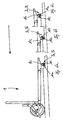
- FIGS. 6a to 6d show one with load roller devices 9a, 9b according to the FIGS. 5a to 5d equipped lifting truck 1 when driving over a trained example as a curbside larger obstacle whose height corresponds to the diameter of the load rollers.
- the load roller carrier 12 is in this case opposite to in the FIG. 6a shown position in a rotated by a rotation angle of 120 ° position.
- a transverse pallet simply be driven under and transported.
- the lifting truck 1 according to the invention is particularly suitable for applications outside of warehouses and production plants, where an uneven road surface is given, for example, on streets and squares, since by the load roller devices 9a, 9b invention in conjunction with a pneumatic tire driving drive unit having larger obstacles of the road For example, curbs and curbs lowering, whose height corresponds to the diameter of the load rollers or exceeds, can be overcome easily and safely.
Landscapes
- Engineering & Computer Science (AREA)
- Chemical & Material Sciences (AREA)
- Combustion & Propulsion (AREA)
- Transportation (AREA)
- Mechanical Engineering (AREA)
- Handcart (AREA)
Claims (13)
- Chariot élévateur (1), en particulier chariot élévateur à faible levée, comprenant une partie d'entraînement (2) et une partie de charge (3) déplaçable verticalement par rapport à la partie d'entraînement (2), laquelle présente des bras de charge (6a ; 6b) qui sont supportés sur une voie de conduite au moyen d'un dispositif de rouleaux de charge (9a ; 9b) respectif présentant au moins deux rouleaux de charge (11a ; 11b ; 11c), les rouleaux de charge (11a ; 11b ; 11c) étant supportés de manière rotative dans un support de rouleaux de charge (12) respectif qui est supporté de manière rotative sur un bras pivotant (14), le bras pivotant (14), pour le déplacement vertical des bras de charge (6a ; 6b), étant disposé de manière à pouvoir pivoter par rapport à la partie d'entraînement (2) sur le bras de charge (6a ; 6b), et les rouleaux de charge (11a ; 11b ; 11c) étant disposés de manière décalée latéralement dans le support de rouleaux de charge (12) et de manière superposée dans la direction longitudinale, le dispositif de rouleaux de charge (9a ; 9b) présentant à chaque fois deux rouleaux de charge (11a ; 11b) et dans chaque support de rouleaux de charge (12) étant disposés deux rouleaux de charge (11a ; 11b), le support de rouleaux de charge (12) étant pourvu d'au moins un contour (20a ; 20b) de forme courbe s'étendant vers le haut, caractérisé en ce que le support de rouleaux de charge (12) est pourvu d'au moins un corps de remplissage (22a ; 22b) entourant au moins en partie les rouleaux de charge (11a ; 11b) dans au moins une direction de conduite, lequel corps de remplissage est adapté au contour (20a ; 20b) de forme courbe du support de rouleaux de charge (12), ou le support de rouleaux de charge (12) est pourvu d'au moins un rouleau supplémentaire (25a ; 25b) en forme de cylindre entourant au moins en partie les rouleaux de charge (11a ; 11b) dans au moins une direction de conduite, lequel rouleau supplémentaire, pendant le fonctionnement de conduite normal, n'est pas en contact avec la voie de conduite et est disposé avant le rouleau de charge correspondant (11a ; 11b) au niveau de la région supérieure du support de rouleaux de charge (12).
- Chariot élévateur selon la revendication 1, caractérisé en ce que le contour (20a ; 20b) s'étend depuis une région proche du sol jusqu'à une région éloignée du sol, qui correspond essentiellement à la hauteur des rouleaux de charge (11a ; 11b).
- Chariot élévateur selon la revendication 1 ou 2, caractérisé en ce que le support de rouleaux de charge (12) entoure les rouleaux de charge (11a ; 11b) dans les deux directions de conduite, le support de rouleaux de charge (12) étant pourvu, pour chaque direction de conduite, d'un contour (20a, 20b) de forme courbe respectif s'étendant vers le haut.
- Chariot élévateur selon l'une quelconque des revendications 1 à 3, caractérisé en ce qu'au moins une butée est prévue au niveau du support de rouleaux de charge (12) pour limiter le mouvement de pivotement du support de rouleaux de charge (12) par rapport au bras pivotant (14).
- Chariot élévateur selon la revendication 4, caractérisé en ce que la butée est formée par au moins un tourillon de butée (21a ; 21b) disposé au niveau du support de rouleaux de charge (12), lequel tourillon de butée peut être amené en liaison fonctionnelle avec le bras pivotant (14).
- Chariot élévateur selon l'une quelconque des revendications 1 à 5, caractérisé en ce que le rouleau supplémentaire (25a ; 25b) est supporté de manière rotative dans le support de rouleaux de charge (12) dans la région éloignée du sol avant le rouleau de charge correspondant (11a ; 11b).
- Chariot élévateur selon la revendication 6, caractérisé en ce que le rouleau supplémentaire (25a ; 25b) est disposé à l'extrémité supérieure du contour (20a ; 20b) de forme courbe au niveau du support de rouleaux de charge (12).
- Chariot élévateur selon la revendication 6 ou 7, caractérisé en ce qu'il est prévu un rouleau supplémentaire (25a ; 25b) pour chaque direction de conduite.
- Chariot élévateur selon l'une quelconque des revendications 1 à 8, caractérisé en ce que l'axe de pivotement (15) du support de rouleaux de charge (12) dans le bras pivotant (14) est disposé centralement entre les axes de rotation (13a ; 13b) des rouleaux de charge (11a ; 11b).
- Chariot élévateur (1), en particulier chariot élévateur à faible levée, comprenant une partie d'entraînement (2) et une partie de charge (3) déplaçable verticalement par rapport à la partie d'entraînement (2), laquelle présente des bras de charge (6a ; 6b) qui sont supportés sur une voie de conduite au moyen d'un dispositif de rouleaux de charge (9a ; 9b) respectif présentant au moins deux rouleaux de charge (11a ; 11b ; 11c), les rouleaux de charge (11a ; 11b ; 11c) étant supportés de manière rotative dans un support de rouleaux de charge (12) respectif qui est supporté de manière rotative sur un bras pivotant (14), le bras pivotant (14), pour le déplacement vertical des bras de charge (6a ; 6b), étant disposé de manière à pouvoir pivoter par rapport à la partie d'entraînement (2) sur le bras de charge (6a ; 6b), et les rouleaux de charge (11a ; 11b ; 11c) étant disposés de manière décalée latéralement dans le support de rouleaux de charge (12) et de manière superposée dans la direction longitudinale, caractérisé en ce que le dispositif de rouleaux de charge (9a ; 9b) présente à chaque fois trois rouleaux de charge (11a ; 11b ; 11c), trois rouleaux de charge (11a ; 11b ; 11c) étant disposés sous forme d'étoile dans chaque support de rouleaux de charge (12).
- Chariot élévateur selon la revendication 10, caractérisé en ce que le support de rouleaux de charge (12) est pourvu essentiellement d'un contour de forme triangulaire, les axes de rotation (13a ; 13b ; 13c) des rouleaux de charge (11a ; 11b ; 11c) étant disposés sous forme de triangle équilatéral.
- Chariot élévateur selon la revendication 11, caractérisé en ce que l'axe de rotation (15) du support de rouleaux de charge (12) dans le bras pivotant (14) présente à chaque fois la même distance aux axes de rotation (13a ; 13b ; 13c) des rouleaux de charge (11a ; 11b ; 11c).
- Chariot élévateur selon l'une quelconque des revendications précédentes, caractérisé en ce que les bras de charge (6a ; 6b) sont à chaque fois réalisés de manière ouverte vers le haut dans la région du dispositif de rouleaux de charge (9a ; 9b).
Applications Claiming Priority (1)
| Application Number | Priority Date | Filing Date | Title |
|---|---|---|---|
| DE102007036177A DE102007036177A1 (de) | 2007-08-02 | 2007-08-02 | Hubwagen mit Lastarmen |
Publications (3)
| Publication Number | Publication Date |
|---|---|
| EP2020358A2 EP2020358A2 (fr) | 2009-02-04 |
| EP2020358A3 EP2020358A3 (fr) | 2011-08-31 |
| EP2020358B1 true EP2020358B1 (fr) | 2015-08-26 |
Family
ID=39929599
Family Applications (1)
| Application Number | Title | Priority Date | Filing Date |
|---|---|---|---|
| EP08009973.2A Active EP2020358B1 (fr) | 2007-08-02 | 2008-05-30 | Chariot élévateur doté de bras de charge |
Country Status (3)
| Country | Link |
|---|---|
| EP (1) | EP2020358B1 (fr) |
| JP (1) | JP5371316B2 (fr) |
| DE (1) | DE102007036177A1 (fr) |
Families Citing this family (7)
| Publication number | Priority date | Publication date | Assignee | Title |
|---|---|---|---|---|
| ES2394920T3 (es) * | 2005-04-14 | 2013-02-06 | Nacco Materials Handling Group, Inc. | Sistema de estabilidad para un vehículo industrial |
| SE539677C2 (en) * | 2014-09-19 | 2017-10-31 | Toyota Mat Handling Mfg Sweden Ab | Forklift truck and method for climbing an obstacle |
| DE102016107538A1 (de) | 2016-04-22 | 2017-10-26 | Jungheinrich Aktiengesellschaft | Flurförderzeug mit einem Paar von in der Höhe verstellbaren Gabelarmen |
| DE102016108165A1 (de) * | 2016-05-03 | 2017-11-09 | Rainer Müllenbach | Transportvorrichtung für Wertstoff- und/oder Abfallbehälter |
| US11745778B2 (en) * | 2019-10-18 | 2023-09-05 | Hyster-Yale Group, Inc. | Load wheel designs for pallet entry |
| US11365103B2 (en) | 2019-03-27 | 2022-06-21 | Hyster-Yale Group, Inc. | Modular fork assembly for a material-handling vehicle |
| US12397836B2 (en) * | 2019-03-27 | 2025-08-26 | Hyster-Yale Materials Handling, Inc. | Modular fork assembly for a forked material-handling vehicle |
Family Cites Families (9)
| Publication number | Priority date | Publication date | Assignee | Title |
|---|---|---|---|---|
| JPS4812937Y1 (fr) * | 1968-11-13 | 1973-04-09 | ||
| JPS4721796Y1 (fr) * | 1968-12-02 | 1972-07-18 | ||
| DE2510586A1 (de) * | 1975-03-11 | 1976-09-16 | Steinbock Gmbh | Gabelhubwagen zum befahren von profilierten fahrflaechen |
| JPH10226337A (ja) * | 1997-02-12 | 1998-08-25 | Akatsui Katsumi | 階段および段差昇降に適した車輪装置およびハンドカート |
| DE19741764C1 (de) * | 1997-09-22 | 1999-04-22 | Ice Cargo Equipment Ag | Hubwagen |
| DE19939295A1 (de) | 1999-08-19 | 2001-02-22 | Still & Saxby Sarl | Flurförderzeug mit Lastrollen |
| JP2004268857A (ja) * | 2003-03-11 | 2004-09-30 | Ricoh Co Ltd | キャスタ |
| JP2006103518A (ja) * | 2004-10-06 | 2006-04-20 | Saburo Mashita | 段差乗り越え機能付走行台車 |
| US20060232030A1 (en) * | 2005-04-14 | 2006-10-19 | Nmhg Oregon, Llc | Multi-axis load rollers for an industrial vehicle |
-
2007
- 2007-08-02 DE DE102007036177A patent/DE102007036177A1/de not_active Withdrawn
-
2008
- 2008-05-30 EP EP08009973.2A patent/EP2020358B1/fr active Active
- 2008-08-01 JP JP2008199185A patent/JP5371316B2/ja not_active Expired - Fee Related
Also Published As
| Publication number | Publication date |
|---|---|
| JP2009035254A (ja) | 2009-02-19 |
| DE102007036177A1 (de) | 2009-02-05 |
| EP2020358A3 (fr) | 2011-08-31 |
| JP5371316B2 (ja) | 2013-12-18 |
| EP2020358A2 (fr) | 2009-02-04 |
Similar Documents
| Publication | Publication Date | Title |
|---|---|---|
| DE102014100865B4 (de) | Routenzuganhänger mit einem Fahrgestell und einer Transportvorrichtung | |
| EP2186713B1 (fr) | Dispositif de ballastage et véhicule agricole équipé avec ce dernier | |
| EP2917070B1 (fr) | Véhicule de transport de charges lourdes servant au transport d'un objet allongé | |
| EP2020358A2 (fr) | Chariot élévateur doté de bras de charge | |
| EP2719603A1 (fr) | Chariot de manutention doté de galets de charge agencés dans des supports de galets de charge pivotants | |
| EP2013041B1 (fr) | Appareil de transport | |
| EP2042410B1 (fr) | Véhicule agricole | |
| EP2719601B1 (fr) | Chariot de manutention, en particulier chariot élévateur | |
| DE202018101228U1 (de) | Palettenhubanhänger | |
| EP1541412A1 (fr) | Système de hayon élévateur | |
| DE3732724C2 (fr) | ||
| EP2019014B1 (fr) | Chariot élévateur | |
| DE102016107538A1 (de) | Flurförderzeug mit einem Paar von in der Höhe verstellbaren Gabelarmen | |
| EP1077169B1 (fr) | Chariot de manutention comprenant des roues de support | |
| DE102006014338B4 (de) | Schlepper zum Transport von fahrbaren Transportbehältern | |
| EP4201192B1 (fr) | Dispositif d'arrimage du chargement pour wagons agricoles | |
| EP2066538B1 (fr) | Portique de lavage et procédé de montage d'un portique de lavage | |
| DE102009004403A1 (de) | Flurförderzeug, insbesondere Hubwagen, mit einer Lastrolleneinrichtung | |
| EP1106431B1 (fr) | Système de hayon élévateur | |
| EP4046866A1 (fr) | Système d'hayon élévateur pourvu de protection mobile contre l'encastrement | |
| EP2518005B1 (fr) | Chariot de manutention | |
| EP3971029B1 (fr) | Remorque de chariot tracteur | |
| EP4110685B1 (fr) | Dispositif de levage d'une remorque de train de manutention et remorque de train de manutention comportant un dispositif de levage | |
| DE20014472U1 (de) | Niederhubwagen | |
| DE202023101673U1 (de) | Hebebühne für ein Fahrzeug |
Legal Events
| Date | Code | Title | Description |
|---|---|---|---|
| PUAI | Public reference made under article 153(3) epc to a published international application that has entered the european phase |
Free format text: ORIGINAL CODE: 0009012 |
|
| AK | Designated contracting states |
Kind code of ref document: A2 Designated state(s): AT BE BG CH CY CZ DE DK EE ES FI FR GB GR HR HU IE IS IT LI LT LU LV MC MT NL NO PL PT RO SE SI SK TR |
|
| AX | Request for extension of the european patent |
Extension state: AL BA MK RS |
|
| PUAL | Search report despatched |
Free format text: ORIGINAL CODE: 0009013 |
|
| AK | Designated contracting states |
Kind code of ref document: A3 Designated state(s): AT BE BG CH CY CZ DE DK EE ES FI FR GB GR HR HU IE IS IT LI LT LU LV MC MT NL NO PL PT RO SE SI SK TR |
|
| AX | Request for extension of the european patent |
Extension state: AL BA MK RS |
|
| RIC1 | Information provided on ipc code assigned before grant |
Ipc: B62B 5/02 20060101ALI20110725BHEP Ipc: B62B 3/06 20060101AFI20110725BHEP |
|
| 17P | Request for examination filed |
Effective date: 20120215 |
|
| AKX | Designation fees paid |
Designated state(s): AT BE BG CH CY CZ DE DK EE ES FI FR GB GR HR HU IE IS IT LI LT LU LV MC MT NL NO PL PT RO SE SI SK TR |
|
| 17Q | First examination report despatched |
Effective date: 20140131 |
|
| GRAP | Despatch of communication of intention to grant a patent |
Free format text: ORIGINAL CODE: EPIDOSNIGR1 |
|
| INTG | Intention to grant announced |
Effective date: 20150324 |
|
| GRAP | Despatch of communication of intention to grant a patent |
Free format text: ORIGINAL CODE: EPIDOSNIGR1 |
|
| GRAS | Grant fee paid |
Free format text: ORIGINAL CODE: EPIDOSNIGR3 |
|
| GRAA | (expected) grant |
Free format text: ORIGINAL CODE: 0009210 |
|
| INTG | Intention to grant announced |
Effective date: 20150707 |
|
| AK | Designated contracting states |
Kind code of ref document: B1 Designated state(s): AT BE BG CH CY CZ DE DK EE ES FI FR GB GR HR HU IE IS IT LI LT LU LV MC MT NL NO PL PT RO SE SI SK TR |
|
| REG | Reference to a national code |
Ref country code: GB Ref legal event code: FG4D Free format text: NOT ENGLISH |
|
| REG | Reference to a national code |
Ref country code: CH Ref legal event code: EP |
|
| REG | Reference to a national code |
Ref country code: AT Ref legal event code: REF Ref document number: 744996 Country of ref document: AT Kind code of ref document: T Effective date: 20150915 |
|
| REG | Reference to a national code |
Ref country code: IE Ref legal event code: FG4D Free format text: LANGUAGE OF EP DOCUMENT: GERMAN |
|
| REG | Reference to a national code |
Ref country code: DE Ref legal event code: R096 Ref document number: 502008013300 Country of ref document: DE |
|
| REG | Reference to a national code |
Ref country code: LT Ref legal event code: MG4D |
|
| PG25 | Lapsed in a contracting state [announced via postgrant information from national office to epo] |
Ref country code: LV Free format text: LAPSE BECAUSE OF FAILURE TO SUBMIT A TRANSLATION OF THE DESCRIPTION OR TO PAY THE FEE WITHIN THE PRESCRIBED TIME-LIMIT Effective date: 20150826 Ref country code: GR Free format text: LAPSE BECAUSE OF FAILURE TO SUBMIT A TRANSLATION OF THE DESCRIPTION OR TO PAY THE FEE WITHIN THE PRESCRIBED TIME-LIMIT Effective date: 20151127 Ref country code: NO Free format text: LAPSE BECAUSE OF FAILURE TO SUBMIT A TRANSLATION OF THE DESCRIPTION OR TO PAY THE FEE WITHIN THE PRESCRIBED TIME-LIMIT Effective date: 20151126 Ref country code: FI Free format text: LAPSE BECAUSE OF FAILURE TO SUBMIT A TRANSLATION OF THE DESCRIPTION OR TO PAY THE FEE WITHIN THE PRESCRIBED TIME-LIMIT Effective date: 20150826 Ref country code: LT Free format text: LAPSE BECAUSE OF FAILURE TO SUBMIT A TRANSLATION OF THE DESCRIPTION OR TO PAY THE FEE WITHIN THE PRESCRIBED TIME-LIMIT Effective date: 20150826 |
|
| REG | Reference to a national code |
Ref country code: NL Ref legal event code: MP Effective date: 20150826 |
|
| PG25 | Lapsed in a contracting state [announced via postgrant information from national office to epo] |
Ref country code: IS Free format text: LAPSE BECAUSE OF FAILURE TO SUBMIT A TRANSLATION OF THE DESCRIPTION OR TO PAY THE FEE WITHIN THE PRESCRIBED TIME-LIMIT Effective date: 20151226 Ref country code: SE Free format text: LAPSE BECAUSE OF FAILURE TO SUBMIT A TRANSLATION OF THE DESCRIPTION OR TO PAY THE FEE WITHIN THE PRESCRIBED TIME-LIMIT Effective date: 20150826 Ref country code: HR Free format text: LAPSE BECAUSE OF FAILURE TO SUBMIT A TRANSLATION OF THE DESCRIPTION OR TO PAY THE FEE WITHIN THE PRESCRIBED TIME-LIMIT Effective date: 20150826 Ref country code: ES Free format text: LAPSE BECAUSE OF FAILURE TO SUBMIT A TRANSLATION OF THE DESCRIPTION OR TO PAY THE FEE WITHIN THE PRESCRIBED TIME-LIMIT Effective date: 20150826 Ref country code: PT Free format text: LAPSE BECAUSE OF FAILURE TO SUBMIT A TRANSLATION OF THE DESCRIPTION OR TO PAY THE FEE WITHIN THE PRESCRIBED TIME-LIMIT Effective date: 20151228 Ref country code: PL Free format text: LAPSE BECAUSE OF FAILURE TO SUBMIT A TRANSLATION OF THE DESCRIPTION OR TO PAY THE FEE WITHIN THE PRESCRIBED TIME-LIMIT Effective date: 20150826 |
|
| PG25 | Lapsed in a contracting state [announced via postgrant information from national office to epo] |
Ref country code: NL Free format text: LAPSE BECAUSE OF FAILURE TO SUBMIT A TRANSLATION OF THE DESCRIPTION OR TO PAY THE FEE WITHIN THE PRESCRIBED TIME-LIMIT Effective date: 20150826 |
|
| PG25 | Lapsed in a contracting state [announced via postgrant information from national office to epo] |
Ref country code: DK Free format text: LAPSE BECAUSE OF FAILURE TO SUBMIT A TRANSLATION OF THE DESCRIPTION OR TO PAY THE FEE WITHIN THE PRESCRIBED TIME-LIMIT Effective date: 20150826 Ref country code: CZ Free format text: LAPSE BECAUSE OF FAILURE TO SUBMIT A TRANSLATION OF THE DESCRIPTION OR TO PAY THE FEE WITHIN THE PRESCRIBED TIME-LIMIT Effective date: 20150826 Ref country code: SK Free format text: LAPSE BECAUSE OF FAILURE TO SUBMIT A TRANSLATION OF THE DESCRIPTION OR TO PAY THE FEE WITHIN THE PRESCRIBED TIME-LIMIT Effective date: 20150826 Ref country code: EE Free format text: LAPSE BECAUSE OF FAILURE TO SUBMIT A TRANSLATION OF THE DESCRIPTION OR TO PAY THE FEE WITHIN THE PRESCRIBED TIME-LIMIT Effective date: 20150826 Ref country code: IT Free format text: LAPSE BECAUSE OF FAILURE TO SUBMIT A TRANSLATION OF THE DESCRIPTION OR TO PAY THE FEE WITHIN THE PRESCRIBED TIME-LIMIT Effective date: 20150826 |
|
| REG | Reference to a national code |
Ref country code: FR Ref legal event code: PLFP Year of fee payment: 9 |
|
| REG | Reference to a national code |
Ref country code: DE Ref legal event code: R097 Ref document number: 502008013300 Country of ref document: DE |
|
| PG25 | Lapsed in a contracting state [announced via postgrant information from national office to epo] |
Ref country code: RO Free format text: LAPSE BECAUSE OF FAILURE TO SUBMIT A TRANSLATION OF THE DESCRIPTION OR TO PAY THE FEE WITHIN THE PRESCRIBED TIME-LIMIT Effective date: 20150826 |
|
| PLBE | No opposition filed within time limit |
Free format text: ORIGINAL CODE: 0009261 |
|
| STAA | Information on the status of an ep patent application or granted ep patent |
Free format text: STATUS: NO OPPOSITION FILED WITHIN TIME LIMIT |
|
| 26N | No opposition filed |
Effective date: 20160530 |
|
| PG25 | Lapsed in a contracting state [announced via postgrant information from national office to epo] |
Ref country code: BE Free format text: LAPSE BECAUSE OF NON-PAYMENT OF DUE FEES Effective date: 20160531 Ref country code: SI Free format text: LAPSE BECAUSE OF FAILURE TO SUBMIT A TRANSLATION OF THE DESCRIPTION OR TO PAY THE FEE WITHIN THE PRESCRIBED TIME-LIMIT Effective date: 20150826 |
|
| PG25 | Lapsed in a contracting state [announced via postgrant information from national office to epo] |
Ref country code: LU Free format text: LAPSE BECAUSE OF FAILURE TO SUBMIT A TRANSLATION OF THE DESCRIPTION OR TO PAY THE FEE WITHIN THE PRESCRIBED TIME-LIMIT Effective date: 20160530 |
|
| REG | Reference to a national code |
Ref country code: CH Ref legal event code: PL |
|
| REG | Reference to a national code |
Ref country code: DE Ref legal event code: R082 Ref document number: 502008013300 Country of ref document: DE Representative=s name: PATENTSHIP PATENTANWALTSGESELLSCHAFT MBH, DE |
|
| PG25 | Lapsed in a contracting state [announced via postgrant information from national office to epo] |
Ref country code: LI Free format text: LAPSE BECAUSE OF NON-PAYMENT OF DUE FEES Effective date: 20160531 Ref country code: CH Free format text: LAPSE BECAUSE OF NON-PAYMENT OF DUE FEES Effective date: 20160531 |
|
| REG | Reference to a national code |
Ref country code: DE Ref legal event code: R082 Ref document number: 502008013300 Country of ref document: DE Representative=s name: PATENTSHIP PATENTANWALTSGESELLSCHAFT MBH, DE |
|
| REG | Reference to a national code |
Ref country code: IE Ref legal event code: MM4A |
|
| REG | Reference to a national code |
Ref country code: FR Ref legal event code: PLFP Year of fee payment: 10 |
|
| PG25 | Lapsed in a contracting state [announced via postgrant information from national office to epo] |
Ref country code: IE Free format text: LAPSE BECAUSE OF NON-PAYMENT OF DUE FEES Effective date: 20160530 |
|
| REG | Reference to a national code |
Ref country code: AT Ref legal event code: MM01 Ref document number: 744996 Country of ref document: AT Kind code of ref document: T Effective date: 20160530 |
|
| PG25 | Lapsed in a contracting state [announced via postgrant information from national office to epo] |
Ref country code: AT Free format text: LAPSE BECAUSE OF NON-PAYMENT OF DUE FEES Effective date: 20160530 |
|
| REG | Reference to a national code |
Ref country code: FR Ref legal event code: PLFP Year of fee payment: 11 |
|
| PG25 | Lapsed in a contracting state [announced via postgrant information from national office to epo] |
Ref country code: CY Free format text: LAPSE BECAUSE OF FAILURE TO SUBMIT A TRANSLATION OF THE DESCRIPTION OR TO PAY THE FEE WITHIN THE PRESCRIBED TIME-LIMIT Effective date: 20150826 Ref country code: HU Free format text: LAPSE BECAUSE OF FAILURE TO SUBMIT A TRANSLATION OF THE DESCRIPTION OR TO PAY THE FEE WITHIN THE PRESCRIBED TIME-LIMIT; INVALID AB INITIO Effective date: 20080530 |
|
| PG25 | Lapsed in a contracting state [announced via postgrant information from national office to epo] |
Ref country code: MC Free format text: LAPSE BECAUSE OF FAILURE TO SUBMIT A TRANSLATION OF THE DESCRIPTION OR TO PAY THE FEE WITHIN THE PRESCRIBED TIME-LIMIT Effective date: 20150826 Ref country code: TR Free format text: LAPSE BECAUSE OF FAILURE TO SUBMIT A TRANSLATION OF THE DESCRIPTION OR TO PAY THE FEE WITHIN THE PRESCRIBED TIME-LIMIT Effective date: 20150826 Ref country code: MT Free format text: LAPSE BECAUSE OF FAILURE TO SUBMIT A TRANSLATION OF THE DESCRIPTION OR TO PAY THE FEE WITHIN THE PRESCRIBED TIME-LIMIT Effective date: 20150826 |
|
| PG25 | Lapsed in a contracting state [announced via postgrant information from national office to epo] |
Ref country code: BG Free format text: LAPSE BECAUSE OF FAILURE TO SUBMIT A TRANSLATION OF THE DESCRIPTION OR TO PAY THE FEE WITHIN THE PRESCRIBED TIME-LIMIT Effective date: 20150826 |
|
| P01 | Opt-out of the competence of the unified patent court (upc) registered |
Effective date: 20230507 |
|
| PGFP | Annual fee paid to national office [announced via postgrant information from national office to epo] |
Ref country code: DE Payment date: 20250519 Year of fee payment: 18 |
|
| PGFP | Annual fee paid to national office [announced via postgrant information from national office to epo] |
Ref country code: GB Payment date: 20250522 Year of fee payment: 18 |
|
| PGFP | Annual fee paid to national office [announced via postgrant information from national office to epo] |
Ref country code: FR Payment date: 20250521 Year of fee payment: 18 |