EP2020370A1 - Véhicule de type à siège en califourchon - Google Patents
Véhicule de type à siège en califourchon Download PDFInfo
- Publication number
- EP2020370A1 EP2020370A1 EP08252514A EP08252514A EP2020370A1 EP 2020370 A1 EP2020370 A1 EP 2020370A1 EP 08252514 A EP08252514 A EP 08252514A EP 08252514 A EP08252514 A EP 08252514A EP 2020370 A1 EP2020370 A1 EP 2020370A1
- Authority
- EP
- European Patent Office
- Prior art keywords
- reflector
- headlight
- cowl
- vehicle
- flasher lamp
- Prior art date
- Legal status (The legal status is an assumption and is not a legal conclusion. Google has not performed a legal analysis and makes no representation as to the accuracy of the status listed.)
- Granted
Links
Images


Classifications
-
- B—PERFORMING OPERATIONS; TRANSPORTING
- B60—VEHICLES IN GENERAL
- B60Q—ARRANGEMENT OF SIGNALLING OR LIGHTING DEVICES, THE MOUNTING OR SUPPORTING THEREOF OR CIRCUITS THEREFOR, FOR VEHICLES IN GENERAL
- B60Q1/00—Arrangement of optical signalling or lighting devices, the mounting or supporting thereof or circuits therefor
- B60Q1/0029—Spatial arrangement
- B60Q1/0041—Spatial arrangement of several lamps in relation to each other
-
- B—PERFORMING OPERATIONS; TRANSPORTING
- B62—LAND VEHICLES FOR TRAVELLING OTHERWISE THAN ON RAILS
- B62J—CYCLE SADDLES OR SEATS; AUXILIARY DEVICES OR ACCESSORIES SPECIALLY ADAPTED TO CYCLES AND NOT OTHERWISE PROVIDED FOR, e.g. ARTICLE CARRIERS OR CYCLE PROTECTORS
- B62J6/00—Arrangement of optical signalling or lighting devices on cycles; Mounting or supporting thereof; Circuits therefor
- B62J6/02—Headlights
- B62J6/022—Headlights specially adapted for motorcycles or the like
- B62J6/026—Headlights specially adapted for motorcycles or the like characterised by the structure, e.g. casings
Definitions
- the present invention relates to a straddle-type vehicle, in which a headlight and a flasher lamp are provided on a body cowl.
- a method of providing a body cowl forwardly of a steering head pipe is widely used in straddle-type vehicles such as motorcycles, etc.
- a body cowl is provided with a headlight and a flasher lamp.
- a headlight includes a headlight bulb and a reflector, by which light irradiated from the headlight bulb is reflected forward.
- a front portion of the headlight is covered by a headlight lens mounted along an outer periphery of the reflector.
- straddle-type vehicles provided with a body cowl
- a construction is known in which a headlight is provided centrally of the body cowl and a pair ot flasher lamps are provided on right and left ends.
- Such an arrangement is disclosed in, for example, JP-A-2005-41476 . In this manner, by separating the flasher lamps from the headlight, it is possible to suppress a decrease in visibility of the flasher lamps when the headlight is illuminated.
- the body cowl described above involves the following problem. That is, in order to ensure the visibility of the flasher lamp, it is necessary to separate the flasher lamps from the headlight, thus causing a problem that it is difficult to make a vehicle width small.
- a flasher lamp having a large luminance it is conceivable to use a flasher lamp having a large luminance to thereby make the flasher lamp close to a headlight while ensuring the visibility of the flasher lamp.
- a flasher lamp having a large luminance is large in power consumption and so not preferable.
- the invention has been thought of in view of the situation and has its object to provide a straddle-type vehicle having a small vehicle width while ensuring visibility of a flasher lamp.
- a straddle-type vehicle comprising:
- the reflector may include a reflector planar portion formed rearward of the reflector straight portion to be made planar.
- the reflector may further include a reflector outer wall formed outwardly of the reflector from the reflector straight portion as viewed from the front of a vehicle.
- the reflector outer wall may be extended rearward from the reflector straight portion.
- an outer periphery of the flasher lamp may include a flasher lamp straight portion formed straight.
- the reflector straight portion and the flasher lamp straight portion may be arranged substantially in parallel to each other.
- the flasher lamp straight portion may be positioned toward the headlight lens on the outer periphery of the flasher lamp.
- the body cowl may include an upper cowl portion, on which the headlight unit is provided, a lower cowl portion, on which the flasher lamp is provided, and a constricted portion formed at a boundary of the upper cowl portion and the lower cowl portion.
- the upper cowl portion may be smaller in width than the lower cowl portion.
- the outer periphery of the reflector may further include a first curved portion and a second curved portion, which are formed curvilinearly.
- One end of the reflector straight portion may be contiguous to the first curved portion.
- the other end of the reflector straight portion may be contiguous to the second curved portion.
- a vehicle comprises a steering head pipe, a body cowl arranged forwardly of the steering head pipe, a headlight unit provided centrally of the body cowl, and a flasher lamp arranged on a side end portion of the body cowl, and that the headlight unit includes a headlight and a headlight lens, which covers the front of the headlight, and the headlight comprises a headlight bulb and a reflector, by which light irradiated from the headlight bulb is reflected forward.
- an outer periphery of the reflector is provided inwardly of an outer periphery of the headlight lens
- the flasher lamp is provided outwardly of the outer periphery of the headlight lens
- the outer periphery of the reflector includes a reflector straight portion formed in a straight manner, and the reflector straight portion is positioned between the headlight bulb and the flasher lamp.
- the outer periphery of the reflector is provided inwardly of an outer periphery of the headlight lens, it is possible to make the flasher lamp close to the headlight lens while ensuring the size of the headlight lens. Consequently, it is possible to decrease the straddle-ride type vehicle in vehicle width.
- the reflector may include a reflector planar portion formed rearward of the reflector straight portion to be made planar.
- the flasher lamp is improved in visibility, it is possible to make the flasher lamps, which are provided at both ends of the body cowl, close to the headlight unit provided centrally of the body cowl. Consequently, it is possible to decrease the straddle-ride type vehicle in vehicle width also in the case where a headlight unit and a flasher lamp are provided integrally on a body cowl.
- the reflector planar portion by forming the reflector planar portion, light irradiated from the headlight bulb can be focused forward as compared with the case where a whole inner wall surface of a reflector is defined by a curved surface.
- the reflector may further include a reflector outer wall formed outwardly of the reflector from the reflector straight portion as viewed from the front of a vehicle, and the reflector outer wall may be extended rearward from the reflector straight portion.
- an outer periphery of the flasher lamp may include a flasher lamp straight portion formed straight.
- the reflector straight portion and the flasher lamp straight portion may be arranged substantially parallel to each other, and the flasher lamp straight portion may be positioned toward the headlight lens on the outer periphery of the flasher lamp.
- the body cowl may include an upper cowl portion, on which the headlight unit is provided, a lower cowl portion, on which the flasher lamp is provided, and a constricted portion formed at a boundary of the upper cowl portion and the lower cowl portion.
- the upper cowl portion may be smaller in width than the lower cowl portion.
- the outer periphery of the reflector may further include a first curved portion and a second curved portion, which are formed curvilinearly.
- One end of the reflector straight portion may be contiguous to the first curved portion and the other end of the reflector straight portion may be contiguous to the second curved portion.
- Fig. 1 is a left side view showing a motorcycle 1 being a straddle-type vehicle according to the embodiment.
- the motorcycle 1 comprises a so-called underbone-type motorcycle, of which a body frame 40 is arranged under as compared with a conventional straddle-type motorcycle.
- the motorcycle 1 comprises a front wheel 20 and a rear wheel 80 and a driving force generated by an engine 50 drives the rear wheel 80.
- the motorcycle 1 is covered by a plurality of body covers. Specifically, the motorcycle 1 is covered by a body cowl 30, a leg shield 36, an undercover 37, a seat undercover 38, and a side cover 39.
- the body cowl 30 is arranged forwardly of a steering head pipe 41.
- the leg shield 36 is arranged forwardly of rider's legs with a rider seated on a seat 70.
- the leg shield 36 is fixed to a downtube 42 extending downward from the steering head pipe 41.
- the body cowl 30 is mounted to the leg shield 36.
- a headlight unit 10 Arranged on the body cowl 30 are a headlight unit 10 and flasher lamps 100L, 100R.
- the flasher lamp 100R is not shown in Fig. 1 (see Fig. 2 ).
- a handle cover 22 is arranged above the body cowl 30 to cover the front of a handle 21.
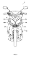
- Fig. 2 is a front view showing the motorcycle 1.
- the headlight unit 10 is provided centrally of the body cowl 30 in a vehicle width direction.
- the flasher lamps 100L, 100R are provided at both sides of the body cowl 30 in the vehicle width direction.
- the body cowl 30 is formed by an upper cowl portion 31 and lower cowl portions 32L, 32R. Constricted portions 33L, 33R are formed at boundaries between the upper cowl portion 31 and the lower cowl portions 32L, 32R. The constricted portions 33L, 33R are formed to be shaped to have a predetermined width in the vehicle width direction. The constricted portions 33L, 33R are extended rearward and upward from a front end of the body cowl 30.
- the upper cowl portion 31 is arranged above the front wheel 20.
- the upper cowl portion 31 is larger in width than the front wheel 20 and extended outwardly of the front wheel 20 in the vehicle width direction.
- the lower cowl portions 32L, 32R are contiguous to the upper cowl portion 31 with the constricted portions 33L, 33R therebetween. Accordingly, the upper cowl portion 31 is smaller in width than the lower cowl portions 32L, 32R. That is, the upper cowl portion 31 is enlarged by the constricted portions 33L, 33R in the vehicle width direction to be contiguous to the lower cowl portions 32L, 32R.
- the lower cowl portion 32L is arranged on a left side of the motorcycle 1 and the lower cowl portion 32R is arranged on a right side of the motorcycle 1. Accordingly, the lower cowl portions 32L, 32R are leg-shaped to extend downward from the upper cowl portion 31.
- the headlight unit 10 is provided centrally of the upper cowl portion 31 in the vehicle width direction.
- the flasher lamps 100L, 100R are provided at both outer ends or sides of the lower cowl portions 32L, 32R in the vehicle width direction.
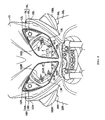
- Fig. 3 is a front view showing, in enlarged scale, the region of boundaries between the upper cowl portion 31 and the lower cowl portions 32L, 32R.
- the headlight unit 10 comprises a headlight 11, headlight lenses 12L, 12R, reflector outer walls 13L, 13R, and position lamps 14L, 14R.
- the headlight 11 comprises a headlight bulb 11a and a reflector 11b.
- the reflector 11b reflects that light, which is irradiated from the headlight bulb 11a, forward. Accordingly, the reflector 11b is formed by using a material having a high reflection effect. A bulb hole, into which the headlight bulb 11a is fitted, is formed centrally of the reflector 11b. The headlight bulb 11a lights up with a predetermined quantity of light or light intensity. The front of the headlight bulb 11a is covered by a part of the upper cowl portion 31.
- the headlight lenses 12L, 12R are arranged to cover the front of the headlight 11.
- the headlight lenses 12L, 12R are arranged symmetrically on the left and right of that portion of the upper cowl portion 31, which covers the front of the headlight bulb 11a.
- the headlight lenses 12L, 12R comprise a colorless, transparent lens.
- an outer periphery of the reflector 11b is formed inwardly of outer peripheries of the headlight lenses 12L, 12R in the vehicle width direction. Also, an outer periphery of the reflector 11b includes reflector straight portions 101L, 101R formed straight, reflector first curved portions 102L, 102R, and reflector second curved portions 103L, 103R.
- An upper end of the reflector straight portion 101L is contiguous to the reflector first curved portion 102L and a lower end of the reflector straight portion 101L is contiguous to the reflector second curved portion 103L.
- the reflector 11b includes reflector planar portions 104L, 104R formed rearward of the reflector straight portions 101L, 101R, respectively, to be made planar. Accordingly, the reflector planar portions 104L, 104R define a part of an inner wall of the reflector 11b.
- the reflector outer walls 13L, 13R are formed outwardly of the reflector 11b from the reflector straight portions 101L, 101R as viewed from the front of a vehicle.
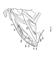
- Fig. 4 is a left side view showing, in enlarged scale, the region of a boundary between the upper cowl portion 31 and the lower cowl portion 32L. As shown in the figure, the reflector outer wall 13L is extended rearward from the reflector straight portion 101L.
- the reflector outer walls 13L, 13R are formed rearward and outward from the reflector straight portions 101L, 101R.
- the reflector outer walls 13L, 13R are formed integral with the reflector 11b by the use of the same material as that of the reflector 11b.
- the position lamps 14L, 14R comprise position lamp reflectors 15L, 15R and position lamp bulbs 16L, 16R. As shown in Fig. 3 , the position lamp reflectors 15L, 15R, respectively, are formed to be triangular-shaped between outer peripheries of the headlight lenses 12L, 12R and an outer periphery of the reflector 11b.
- the flasher lamps 100L, 100R comprise a lens portion and a flasher bulb (only an outward appearance of the lens portion is depicted).
- the lens portion comprises a colorless lens.
- the flasher lamps flash in an amber color (or an orange color) at predetermined intervals.
- the flasher lamps 100L, 100R are fitted into flasher lamp receiving recesses 34L, 34R formed on the body cowl 30 (the lower cowl portions 32L, 32R).
- the flasher lamp receiving recesses 34L, 34R are formed symmetrically at both ends of the lower cowl portions 32L, 32R.
- the flasher lamps 100L, 100R are formed outwardly of the outer peripheries of the headlight lenses 12L, 12R in the vehicle width direction as shown in Fig. 3 .
- the flasher lamps 100L, 100R are formed convexly outwardly in the vehicle width direction. Also, the flasher lamp 100L is larger in size in a vertical direction than in a longitudinal direction. That is, the flasher lamp 100L is crosswise lengthy in shape in a state of being mounted to the lower cowl portion 32L. Also, as shown in the figure, the flasher lamp 100L is similar in shape to a cross section of a blade (airfoil) as viewed laterally of a vehicle body.
- an outer periphery of the flasher lamp 100L (specifically, the lens portion) includes a flasher lamp straight portion 110L formed in a straight manner as shown in Fig. 4 .
- the flasher lamp straight portion 110L is formed to be directed rearward and upward as viewed laterally of a vehicle body.
- the flasher lamp straight portion 110L is positioned toward the headlight lens 12L on the outer periphery of the flasher lamp 100L.
- Fig. 5 is a front view showing, in enlarged scale, the left side of the reflector 11b and the region of the flasher lamp 100L.
- the reflector straight portion 101L is positioned between the headlight bulb 11a and the flasher lamp 100L.
- the reflector straight portion 101L is provided inside the outer periphery of the headlight lens 12L and the flasher lamp straight portion 110L is provided outside the outer periphery of the headlight lens 12L.
- a reference line ⁇ , indicative of a direction, in which the reflector straight portion 101L is extended, and a reference line ⁇ indicative of a direction, in which the flasher lamp straight portion 110L is extended are substantially parallel to each other as viewed from the front of a vehicle. That is, the reflector straight portion 101L and the flasher lamp straight portion 110L are formed substantially parallel to each other as viewed from the front of a vehicle.
- the reflector straight portion 101L and the flasher lamp straight portion 110L are not substantially parallel to each other as viewed laterally of a vehicle body (see Fig. 3 ) and as viewed in plan view of a vehicle body (see Fig. 6 ).
- the outer periphery of the reflector 11b is provided inside the outer peripheries of the headlight lenses 12L, 12R as viewed from the front of a vehicle.
- the flasher lamps 100L, 100R are provided outside the outer peripheries of the headlight lenses 12L, 12R.
- the outer periphery of the reflector 11b includes reflector straight portions 101L, 101R formed in a straight manner.
- the outer periphery of the reflector 11b is provided inside the outer peripheries of the headlight lenses 12L, 12R, so that it is possible to make the flasher lamps 100L, 100R close to the headlight lenses 12L, 12R while ensuring sizes of the headlight lenses 12L, 12R. Consequently, it is possible to decrease the motorcycle 1 in vehicle width.
- the reflector straight portions 101L, 101R are positioned between the headlight bulb 11a and the flasher lamps 100L, 100R.
- the reflector 11b includes the reflector planar portions 104L, 104R formed rearward of the reflector straight portions 101L, 101R to be made planar.
- the flasher lamps are improved in visibility, it is possible to make the flasher lamps 100L, 100R, which are provided at both ends of the body cowl 30, close to the headlight unit 10 provided centrally of the body cowl 30. Consequently, it is possible to decrease the motorcycle 1 in vehicle width also in the case where the headlight unit 10 and the flasher lamps 100L, 100R are provided integrally on the body cowl 30.
- the reflector planar portions 104L, 104R by forming the reflector planar portions 104L, 104R, light irradiated from the headlight bulb 11a can be focused forward as compared with the case where a whole inner wall surface of a reflector is defined by a curved surface.
- the outer periphery of the reflector 11b is provided inside the outer peripheries of the headlight lenses 12L, 12R as viewed from the front of a vehicle.
- the reflector 11b includes the reflector outer walls 13L, 13R formed outward from the reflector straight portions 101L, 101R. Therefore, it is possible to ensure the quality of outward appearance for the headlight 11 also in the case where the outer periphery of the reflector 11b is provided inside the outer peripheries of the headlight lenses 12L, 12R.
- the reflector straight portions 101L, 101R and the flasher lamp straight portions 110L, 110R in the embodiment are arranged substantially in parallel to each other. That is, the outer peripheries of the flasher lamps 100L, 100R are formed to be made straight in conformity to the shapes of the reflector straight portions 101L, 101R. Accordingly, it is possible to make the flasher lamps 100L, 100R further close to the headlight unit 10. Consequently, it is possible to further decrease the motorcycle 1 in vehicle width. Further, it is possible to suppress interference between light irradiated from the headlight bulb 11a and light irradiated from the flasher lamp bulb. Consequently, it is possible to improve the respective lights in visibility.
- the body cowl 30 includes the upper cowl portion 31, on which the headlight unit 10 is provided, the lower cowl portions 32L, 32R, on which the flasher lamps 100L, 100R are provided, and the constricted portions 33L, 33R formed at the boundaries thereof.
- the upper cowl portion 31 is smaller in width than the lower cowl portions 32L, 32R. Therefore, it is possible to further suppress interference between light irradiated from the headlight bulb 11a and light irradiated from the flasher lamp bulb.
- one end of the respective reflector straight portions 101L, 101R are contiguous to the first curved portions 102L, 102R and the other ends thereof are contiguous to the second curved portions 103L, 103R. Therefore, a sufficient quantity of light can be ensured for the headlight 11 by curvilinearly forming a portion of the outer periphery of the reflector 11b except portions thereof toward the flasher lamps 100L, 100R.
- the upper cowl portion 31 covers a part of the headlight 11 in the embodiment, the upper cowl portion 31 may not cover the headlight 11.
Landscapes
- Engineering & Computer Science (AREA)
- Mechanical Engineering (AREA)
- Non-Portable Lighting Devices Or Systems Thereof (AREA)
- Lighting Device Outwards From Vehicle And Optical Signal (AREA)
Applications Claiming Priority (1)
| Application Number | Priority Date | Filing Date | Title |
|---|---|---|---|
| JP2007202264A JP2009035180A (ja) | 2007-08-02 | 2007-08-02 | 鞍乗型車両 |
Publications (2)
| Publication Number | Publication Date |
|---|---|
| EP2020370A1 true EP2020370A1 (fr) | 2009-02-04 |
| EP2020370B1 EP2020370B1 (fr) | 2013-01-09 |
Family
ID=39940587
Family Applications (1)
| Application Number | Title | Priority Date | Filing Date |
|---|---|---|---|
| EP08252514A Active EP2020370B1 (fr) | 2007-08-02 | 2008-07-24 | Véhicule de type à siège en califourchon |
Country Status (5)
| Country | Link |
|---|---|
| EP (1) | EP2020370B1 (fr) |
| JP (1) | JP2009035180A (fr) |
| CN (1) | CN101357654B (fr) |
| BR (1) | BRPI0803846B1 (fr) |
| ES (1) | ES2401471T3 (fr) |
Cited By (2)
| Publication number | Priority date | Publication date | Assignee | Title |
|---|---|---|---|---|
| EP2168850A1 (fr) * | 2008-09-30 | 2010-03-31 | Honda Motor Co., Ltd | Véhicule de type à enfourcher |
| TWI570007B (zh) * | 2014-10-24 | 2017-02-11 | Yamaha Motor Co Ltd | Straddle type vehicle |
Families Citing this family (3)
| Publication number | Priority date | Publication date | Assignee | Title |
|---|---|---|---|---|
| CN102275617B (zh) * | 2010-06-13 | 2013-10-23 | 本田技研工业株式会社 | 跨骑型车辆用车灯器支承装置 |
| JP5651025B2 (ja) * | 2011-01-20 | 2015-01-07 | 本田技研工業株式会社 | ヘッドライト |
| CN105523112B (zh) * | 2014-10-24 | 2018-09-21 | 雅马哈发动机株式会社 | 跨坐型车辆 |
Citations (2)
| Publication number | Priority date | Publication date | Assignee | Title |
|---|---|---|---|---|
| EP1495953A2 (fr) * | 2003-07-07 | 2005-01-12 | Yamaha Hatsudoki Kabushiki Kaisha | Véhicule du type monté a califourchon |
| EP1645466A1 (fr) * | 2004-10-07 | 2006-04-12 | Yamaha Hatsudoki Kabushiki Kaisha | Methode de control d' un projecteur de lumière d'un véhicule et véhicule associé |
-
2007
- 2007-08-02 JP JP2007202264A patent/JP2009035180A/ja active Pending
-
2008
- 2008-07-24 EP EP08252514A patent/EP2020370B1/fr active Active
- 2008-07-24 ES ES08252514T patent/ES2401471T3/es active Active
- 2008-07-30 BR BRPI0803846-5A patent/BRPI0803846B1/pt active IP Right Grant
- 2008-08-04 CN CN2008101342744A patent/CN101357654B/zh active Active
Patent Citations (3)
| Publication number | Priority date | Publication date | Assignee | Title |
|---|---|---|---|---|
| EP1495953A2 (fr) * | 2003-07-07 | 2005-01-12 | Yamaha Hatsudoki Kabushiki Kaisha | Véhicule du type monté a califourchon |
| JP2005041476A (ja) | 2003-07-07 | 2005-02-17 | Yamaha Motor Co Ltd | 鞍乗り型車両 |
| EP1645466A1 (fr) * | 2004-10-07 | 2006-04-12 | Yamaha Hatsudoki Kabushiki Kaisha | Methode de control d' un projecteur de lumière d'un véhicule et véhicule associé |
Cited By (2)
| Publication number | Priority date | Publication date | Assignee | Title |
|---|---|---|---|---|
| EP2168850A1 (fr) * | 2008-09-30 | 2010-03-31 | Honda Motor Co., Ltd | Véhicule de type à enfourcher |
| TWI570007B (zh) * | 2014-10-24 | 2017-02-11 | Yamaha Motor Co Ltd | Straddle type vehicle |
Also Published As
| Publication number | Publication date |
|---|---|
| CN101357654B (zh) | 2012-08-29 |
| CN101357654A (zh) | 2009-02-04 |
| JP2009035180A (ja) | 2009-02-19 |
| ES2401471T3 (es) | 2013-04-19 |
| BRPI0803846A2 (pt) | 2009-05-19 |
| BRPI0803846B1 (pt) | 2018-05-29 |
| EP2020370B1 (fr) | 2013-01-09 |
Similar Documents
| Publication | Publication Date | Title |
|---|---|---|
| JP6257736B2 (ja) | 自動二輪車用前照灯 | |
| CN100516636C (zh) | 用于车辆的灯单元和配备有这种灯单元的摩托车 | |
| EP2020370B1 (fr) | Véhicule de type à siège en califourchon | |
| CN103359226B (zh) | 跨乘式车辆 | |
| CN103448844A (zh) | 骑乘型车辆 | |
| WO2016158889A1 (fr) | Phare | |
| CN1902082B (zh) | 骑坐式车辆 | |
| CN101469821B (zh) | 车辆用照明器结构 | |
| JP6544963B2 (ja) | ヘッドライト | |
| JP6114594B2 (ja) | 鞍乗型車両用リアライト | |
| CN104743008B (zh) | 二轮摩托车的前部结构 | |
| JP2007030809A (ja) | 自動二輪車のランプユニット | |
| JP6858741B2 (ja) | 鞍乗り型車両の前照灯 | |
| JP2012151015A (ja) | ヘッドライト | |
| JP6236047B2 (ja) | 車両用リアコンビネーションランプ及び車両 | |
| JP7478853B2 (ja) | 鞍乗り型車両 | |
| JP6426577B2 (ja) | 車両用リアコンビネーションランプ及び車両 | |
| CN100572895C (zh) | 车辆用灯光器构造 | |
| JP5504016B2 (ja) | ヘッドライト装置 | |
| TWI413599B (zh) | Saddle type vehicle | |
| JP2014166793A (ja) | 鞍乗型車両の灯火器 | |
| EP3305636B1 (fr) | Véhicule de type à selle | |
| JP6579632B2 (ja) | 鞍乗型車両のリヤコンビネーションランプ | |
| BR102021021598A2 (pt) | Dispositivo de iluminação | |
| TW202130542A (zh) | 跨坐型車輛 |
Legal Events
| Date | Code | Title | Description |
|---|---|---|---|
| PUAI | Public reference made under article 153(3) epc to a published international application that has entered the european phase |
Free format text: ORIGINAL CODE: 0009012 |
|
| 17P | Request for examination filed |
Effective date: 20080807 |
|
| AK | Designated contracting states |
Kind code of ref document: A1 Designated state(s): AT BE BG CH CY CZ DE DK EE ES FI FR GB GR HR HU IE IS IT LI LT LU LV MC MT NL NO PL PT RO SE SI SK TR |
|
| AX | Request for extension of the european patent |
Extension state: AL BA MK RS |
|
| AKX | Designation fees paid |
Designated state(s): AT BE BG CH CY CZ DE DK EE ES FI FR GB GR HR HU IE IS IT LI LT LU LV MC MT NL NO PL PT RO SE SI SK TR |
|
| GRAP | Despatch of communication of intention to grant a patent |
Free format text: ORIGINAL CODE: EPIDOSNIGR1 |
|
| RAP1 | Party data changed (applicant data changed or rights of an application transferred) |
Owner name: YAMAHA HATSUDOKI KABUSHIKI KAISHA |
|
| GRAS | Grant fee paid |
Free format text: ORIGINAL CODE: EPIDOSNIGR3 |
|
| GRAA | (expected) grant |
Free format text: ORIGINAL CODE: 0009210 |
|
| AK | Designated contracting states |
Kind code of ref document: B1 Designated state(s): AT BE BG CH CY CZ DE DK EE ES FI FR GB GR HR HU IE IS IT LI LT LU LV MC MT NL NO PL PT RO SE SI SK TR |
|
| REG | Reference to a national code |
Ref country code: GB Ref legal event code: FG4D |
|
| REG | Reference to a national code |
Ref country code: CH Ref legal event code: EP Ref country code: AT Ref legal event code: REF Ref document number: 592564 Country of ref document: AT Kind code of ref document: T Effective date: 20130115 |
|
| REG | Reference to a national code |
Ref country code: IE Ref legal event code: FG4D |
|
| REG | Reference to a national code |
Ref country code: DE Ref legal event code: R096 Ref document number: 602008021506 Country of ref document: DE Effective date: 20130307 |
|
| REG | Reference to a national code |
Ref country code: ES Ref legal event code: FG2A Ref document number: 2401471 Country of ref document: ES Kind code of ref document: T3 Effective date: 20130419 |
|
| PG25 | Lapsed in a contracting state [announced via postgrant information from national office to epo] |
Ref country code: SI Free format text: LAPSE BECAUSE OF FAILURE TO SUBMIT A TRANSLATION OF THE DESCRIPTION OR TO PAY THE FEE WITHIN THE PRESCRIBED TIME-LIMIT Effective date: 20130109 |
|
| REG | Reference to a national code |
Ref country code: NL Ref legal event code: VDEP Effective date: 20130109 |
|
| REG | Reference to a national code |
Ref country code: AT Ref legal event code: MK05 Ref document number: 592564 Country of ref document: AT Kind code of ref document: T Effective date: 20130109 |
|
| REG | Reference to a national code |
Ref country code: LT Ref legal event code: MG4D |
|
| PG25 | Lapsed in a contracting state [announced via postgrant information from national office to epo] |
Ref country code: BG Free format text: LAPSE BECAUSE OF FAILURE TO SUBMIT A TRANSLATION OF THE DESCRIPTION OR TO PAY THE FEE WITHIN THE PRESCRIBED TIME-LIMIT Effective date: 20130409 Ref country code: BE Free format text: LAPSE BECAUSE OF FAILURE TO SUBMIT A TRANSLATION OF THE DESCRIPTION OR TO PAY THE FEE WITHIN THE PRESCRIBED TIME-LIMIT Effective date: 20130109 Ref country code: IS Free format text: LAPSE BECAUSE OF FAILURE TO SUBMIT A TRANSLATION OF THE DESCRIPTION OR TO PAY THE FEE WITHIN THE PRESCRIBED TIME-LIMIT Effective date: 20130509 Ref country code: NO Free format text: LAPSE BECAUSE OF FAILURE TO SUBMIT A TRANSLATION OF THE DESCRIPTION OR TO PAY THE FEE WITHIN THE PRESCRIBED TIME-LIMIT Effective date: 20130409 Ref country code: LT Free format text: LAPSE BECAUSE OF FAILURE TO SUBMIT A TRANSLATION OF THE DESCRIPTION OR TO PAY THE FEE WITHIN THE PRESCRIBED TIME-LIMIT Effective date: 20130109 Ref country code: AT Free format text: LAPSE BECAUSE OF FAILURE TO SUBMIT A TRANSLATION OF THE DESCRIPTION OR TO PAY THE FEE WITHIN THE PRESCRIBED TIME-LIMIT Effective date: 20130109 Ref country code: SE Free format text: LAPSE BECAUSE OF FAILURE TO SUBMIT A TRANSLATION OF THE DESCRIPTION OR TO PAY THE FEE WITHIN THE PRESCRIBED TIME-LIMIT Effective date: 20130109 |
|
| PG25 | Lapsed in a contracting state [announced via postgrant information from national office to epo] |
Ref country code: FI Free format text: LAPSE BECAUSE OF FAILURE TO SUBMIT A TRANSLATION OF THE DESCRIPTION OR TO PAY THE FEE WITHIN THE PRESCRIBED TIME-LIMIT Effective date: 20130109 Ref country code: LV Free format text: LAPSE BECAUSE OF FAILURE TO SUBMIT A TRANSLATION OF THE DESCRIPTION OR TO PAY THE FEE WITHIN THE PRESCRIBED TIME-LIMIT Effective date: 20130109 Ref country code: PL Free format text: LAPSE BECAUSE OF FAILURE TO SUBMIT A TRANSLATION OF THE DESCRIPTION OR TO PAY THE FEE WITHIN THE PRESCRIBED TIME-LIMIT Effective date: 20130109 Ref country code: GR Free format text: LAPSE BECAUSE OF FAILURE TO SUBMIT A TRANSLATION OF THE DESCRIPTION OR TO PAY THE FEE WITHIN THE PRESCRIBED TIME-LIMIT Effective date: 20130410 Ref country code: PT Free format text: LAPSE BECAUSE OF FAILURE TO SUBMIT A TRANSLATION OF THE DESCRIPTION OR TO PAY THE FEE WITHIN THE PRESCRIBED TIME-LIMIT Effective date: 20130509 Ref country code: NL Free format text: LAPSE BECAUSE OF FAILURE TO SUBMIT A TRANSLATION OF THE DESCRIPTION OR TO PAY THE FEE WITHIN THE PRESCRIBED TIME-LIMIT Effective date: 20130109 |
|
| PG25 | Lapsed in a contracting state [announced via postgrant information from national office to epo] |
Ref country code: HR Free format text: LAPSE BECAUSE OF FAILURE TO SUBMIT A TRANSLATION OF THE DESCRIPTION OR TO PAY THE FEE WITHIN THE PRESCRIBED TIME-LIMIT Effective date: 20130109 |
|
| PG25 | Lapsed in a contracting state [announced via postgrant information from national office to epo] |
Ref country code: SK Free format text: LAPSE BECAUSE OF FAILURE TO SUBMIT A TRANSLATION OF THE DESCRIPTION OR TO PAY THE FEE WITHIN THE PRESCRIBED TIME-LIMIT Effective date: 20130109 Ref country code: EE Free format text: LAPSE BECAUSE OF FAILURE TO SUBMIT A TRANSLATION OF THE DESCRIPTION OR TO PAY THE FEE WITHIN THE PRESCRIBED TIME-LIMIT Effective date: 20130109 Ref country code: RO Free format text: LAPSE BECAUSE OF FAILURE TO SUBMIT A TRANSLATION OF THE DESCRIPTION OR TO PAY THE FEE WITHIN THE PRESCRIBED TIME-LIMIT Effective date: 20130109 Ref country code: CZ Free format text: LAPSE BECAUSE OF FAILURE TO SUBMIT A TRANSLATION OF THE DESCRIPTION OR TO PAY THE FEE WITHIN THE PRESCRIBED TIME-LIMIT Effective date: 20130109 Ref country code: DK Free format text: LAPSE BECAUSE OF FAILURE TO SUBMIT A TRANSLATION OF THE DESCRIPTION OR TO PAY THE FEE WITHIN THE PRESCRIBED TIME-LIMIT Effective date: 20130109 |
|
| PLBE | No opposition filed within time limit |
Free format text: ORIGINAL CODE: 0009261 |
|
| STAA | Information on the status of an ep patent application or granted ep patent |
Free format text: STATUS: NO OPPOSITION FILED WITHIN TIME LIMIT |
|
| PG25 | Lapsed in a contracting state [announced via postgrant information from national office to epo] |
Ref country code: CY Free format text: LAPSE BECAUSE OF FAILURE TO SUBMIT A TRANSLATION OF THE DESCRIPTION OR TO PAY THE FEE WITHIN THE PRESCRIBED TIME-LIMIT Effective date: 20130109 |
|
| 26N | No opposition filed |
Effective date: 20131010 |
|
| REG | Reference to a national code |
Ref country code: DE Ref legal event code: R097 Ref document number: 602008021506 Country of ref document: DE Effective date: 20131010 |
|
| PG25 | Lapsed in a contracting state [announced via postgrant information from national office to epo] |
Ref country code: MC Free format text: LAPSE BECAUSE OF FAILURE TO SUBMIT A TRANSLATION OF THE DESCRIPTION OR TO PAY THE FEE WITHIN THE PRESCRIBED TIME-LIMIT Effective date: 20130109 |
|
| REG | Reference to a national code |
Ref country code: CH Ref legal event code: PL |
|
| GBPC | Gb: european patent ceased through non-payment of renewal fee |
Effective date: 20130724 |
|
| REG | Reference to a national code |
Ref country code: IE Ref legal event code: MM4A |
|
| REG | Reference to a national code |
Ref country code: DE Ref legal event code: R119 Ref document number: 602008021506 Country of ref document: DE Effective date: 20140201 |
|
| PG25 | Lapsed in a contracting state [announced via postgrant information from national office to epo] |
Ref country code: DE Free format text: LAPSE BECAUSE OF NON-PAYMENT OF DUE FEES Effective date: 20140201 Ref country code: CH Free format text: LAPSE BECAUSE OF NON-PAYMENT OF DUE FEES Effective date: 20130731 Ref country code: LI Free format text: LAPSE BECAUSE OF NON-PAYMENT OF DUE FEES Effective date: 20130731 Ref country code: GB Free format text: LAPSE BECAUSE OF NON-PAYMENT OF DUE FEES Effective date: 20130724 |
|
| PG25 | Lapsed in a contracting state [announced via postgrant information from national office to epo] |
Ref country code: IE Free format text: LAPSE BECAUSE OF NON-PAYMENT OF DUE FEES Effective date: 20130724 |
|
| PG25 | Lapsed in a contracting state [announced via postgrant information from national office to epo] |
Ref country code: MT Free format text: LAPSE BECAUSE OF FAILURE TO SUBMIT A TRANSLATION OF THE DESCRIPTION OR TO PAY THE FEE WITHIN THE PRESCRIBED TIME-LIMIT Effective date: 20130109 |
|
| PG25 | Lapsed in a contracting state [announced via postgrant information from national office to epo] |
Ref country code: LU Free format text: LAPSE BECAUSE OF NON-PAYMENT OF DUE FEES Effective date: 20130724 Ref country code: HU Free format text: LAPSE BECAUSE OF FAILURE TO SUBMIT A TRANSLATION OF THE DESCRIPTION OR TO PAY THE FEE WITHIN THE PRESCRIBED TIME-LIMIT; INVALID AB INITIO Effective date: 20080724 |
|
| REG | Reference to a national code |
Ref country code: FR Ref legal event code: PLFP Year of fee payment: 9 |
|
| REG | Reference to a national code |
Ref country code: FR Ref legal event code: PLFP Year of fee payment: 10 |
|
| REG | Reference to a national code |
Ref country code: FR Ref legal event code: PLFP Year of fee payment: 11 |
|
| PGFP | Annual fee paid to national office [announced via postgrant information from national office to epo] |
Ref country code: TR Payment date: 20200723 Year of fee payment: 13 Ref country code: ES Payment date: 20200922 Year of fee payment: 13 |
|
| REG | Reference to a national code |
Ref country code: ES Ref legal event code: FD2A Effective date: 20220928 |
|
| PG25 | Lapsed in a contracting state [announced via postgrant information from national office to epo] |
Ref country code: ES Free format text: LAPSE BECAUSE OF NON-PAYMENT OF DUE FEES Effective date: 20210725 |
|
| P01 | Opt-out of the competence of the unified patent court (upc) registered |
Effective date: 20230526 |
|
| PG25 | Lapsed in a contracting state [announced via postgrant information from national office to epo] |
Ref country code: TR Free format text: LAPSE BECAUSE OF NON-PAYMENT OF DUE FEES Effective date: 20210724 |
|
| PGFP | Annual fee paid to national office [announced via postgrant information from national office to epo] |
Ref country code: IT Payment date: 20250724 Year of fee payment: 18 |
|
| PGFP | Annual fee paid to national office [announced via postgrant information from national office to epo] |
Ref country code: FR Payment date: 20250724 Year of fee payment: 18 |