EP2020379B1 - Ensemble de train d'atterrissage - Google Patents
Ensemble de train d'atterrissage Download PDFInfo
- Publication number
- EP2020379B1 EP2020379B1 EP08252527A EP08252527A EP2020379B1 EP 2020379 B1 EP2020379 B1 EP 2020379B1 EP 08252527 A EP08252527 A EP 08252527A EP 08252527 A EP08252527 A EP 08252527A EP 2020379 B1 EP2020379 B1 EP 2020379B1
- Authority
- EP
- European Patent Office
- Prior art keywords
- wheel support
- support housing
- assembly according
- motor
- relative
- Prior art date
- Legal status (The legal status is an assumption and is not a legal conclusion. Google has not performed a legal analysis and makes no representation as to the accuracy of the status listed.)
- Active
Links
Images

Classifications
-
- B—PERFORMING OPERATIONS; TRANSPORTING
- B64—AIRCRAFT; AVIATION; COSMONAUTICS
- B64C—AEROPLANES; HELICOPTERS
- B64C25/00—Alighting gear
- B64C25/32—Alighting gear characterised by elements which contact the ground or similar surface
- B64C25/50—Steerable undercarriages; Shimmy-damping
Definitions
- This invention relates to a landing gear assembly, and in particular to a steerable landing gear assembly intended for use in the nose landing gear of an aircraft.
- the nose landing gear assembly of an aircraft typically comprises a hydraulic or pneumatic shock absorber arranged to carry, at its lower end, a wheel support housing carrying one, or preferably a pair of wheels arranged coaxially with one another on opposite sides of the wheel support housing.
- a hydraulic or pneumatic shock absorber arranged to carry, at its lower end, a wheel support housing carrying one, or preferably a pair of wheels arranged coaxially with one another on opposite sides of the wheel support housing.
- at least part of the shock absorber may be angularly adjustable, adjustment of the angle thereof adjusting the orientation of the wheel support housing, and hence the axes of the wheels.
- Such adjustment may be achieved using, for example, a rack and pinion arrangement powered hydraulically or electrically though associated torque links.
- Such landing gear assemblies have the advantage that the steering mechanism is located away from the wheel assembly and so is subject to relatively low shock loadings, in use, but the disadvantage that the shock absorber and torque linkage has to be designed in such a manner as to permit the transmission of the steering loads to the wheels.
- Document US 2006/065779 A1 shows a powered nose aircraft wheel system for an aircraft according to the preamble of claim 1.
- the system includes a landing gear that extends from the aircraft.
- a wheel motor is coupled to the wheel axel and the wheel and permits each aircraft nose landing gear wheel to freely spin during the landing or takeoff of the aircraft.
- Document WO 2006/010890 A1 shows an aircraft landing gear including a steering motor which is mounted on a steering collar and engages with pinion teeth attached to the turning collar, whereby the motor rotates relative to the housing and turning collar when the gear is steered.
- a landing gear assembly comprising a wheel support housing rotatably connected to a support member, the wheel support housing containing an electrically powered motor operable to adjust the angular position of the wheel support housing relative to the support member.
- the electrically powered motor may be of the radial flux type, or could be an axial flux, pancake motor.
- the use of an electric pancake motor may be advantageous in that further space saving may be possible.
- the wheel support housing further houses a gear train mechanism, for example in the form of an epicyclic gear arrangement, connected to the output of the electrically powered motor.
- a clutch arrangement is provided, disengagement of the clutch arrangement permitting angular movement of the wheel support housing relative to the support member independently of the operation of the electrically powered motor.
- One or more sensors may be provided to allow monitoring of the angular position of the wheel support housing relative to the support shaft.
- the sensor may comprise, for example, a Hall effect sensor, a shaft position encoder or an RVDT.
- the support member preferably comprises a lower piston tube or shaft of a shock absorber, the lower piston tube being keyed to an upper piston tube or shaft of the shock absorber.
- the upper and lower piston tubes are keyed to one another by a ball spline coupling, which enhances the stiffness of the assembly.
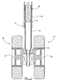
- a landing gear assembly comprising a multi-part wheel support housing 10 rotatably mounted to the lower end of a shock absorber 12.
- the shock absorber 12 is connected to the remainder of an aircraft's nose landing gear (not shown) and comprises an upper, outer piston tube 14 and a lower, inner piston tube 16, the inner and outer piston tubes 14, 16 being dimensioned to allow telescoping movement therebetween.
- a piston member 18 is located within the inner piston tube 16 and forms a seal therewith in the usual manner.
- a ball spline coupling 20 is provided between the upper and lower piston tubes 14, 16 the coupling 20 accommodating relative axial movement therebetween but preventing or substantially preventing relative angular movement therebetween such that the lower piston tube 16 is non-rotatably mounted to the remainder of the landing gear, thereby enhancing the stiffness of the assembly.
- the wheel support housing 10 incorporates a pair of axle regions 22 arranged coaxially with one another and adapted to support associated wheels 24 for rotation relative to the wheel support housing 10.
- the wheel support housing 10 is rotatably mounted to the lower piston tube 16 by a series of bearings 26, thus the lower piston tube 16 forms a support member for the wheel support housing 10.
- the bearings 26 accommodate rotary or angular movement of the wheel support housing 10 relative to the lower piston tube 16, but prevent or restrict relative axial movement therebetween.
- the motor 28 is a radial flux motor of relatively short axial length, but it will be appreciated that other forms of electrically powered motor may be used. For example, it may be preferred to use an axial flux motor, and the use of a pancake motor may be preferred as this may allow additional space savings to be made.
- the motor 28 comprises a stator 30 which is fixed relative to the wheel support housing 10, and a rotor 32 which is rotatable relative to the wheel support housing 10 when the motor 28 is operating.
- the rotor 32 is coupled to an output gear 34 which encircles but is free to rotate relative to an adjacent part of the lower piston tube 16.
- the output gear 34 is arranged to serve as an input, in use, to an epicyclic gear train 36.
- the gear train 36 includes a sun gear 38 upon which a series of idler gears 40 are mounted.
- the sun gear 38 encircles, but is free to rotate relative to, the lower piston tube 16.
- the idler gears 40 are each in meshing engagement with the output gear 34 and also with teeth formations (not shown) provided on the adjacent part of the wheel support housing 10. It will be appreciated that, in use, upon operation of the motor 28, the output gear 34 rotates and this drives each idler gear 40 for rotation about its respective axis of rotation.
- the meshing of the idler gears 40 with the teeth formations provided on the wheel support housing 10 causes the idler gears 40 to precess around the lower piston tube 16, hence driving the sun gear 38 for rotation.
- the precise number of idler gears 40 provided is not important and it is envisaged that around six such gears will be provided.
- the provision of this arrangement results in the sun gear 38 rotating, in use, at a speed lower than the output gear 34.
- the gear train 36 further includes a plurality of planetary gears 42, each of which includes a first toothed region 44 which meshes with both the sun gear 38 and with tooth formations (not shown) provided on the adjacent part of the wheel support housing 10, and a second toothed region 46 which meshes with teeth provided on an output ring gear 48.
- the output ring gear 48 is held against rotation relative to the lower piston tube 16 by a clutch arrangement 53 as will be described below.
- the first and second toothed regions 44, 46 of the planetary gears 42 have a slightly different number of teeth to one another, for example the number of teeth may differ by only one or two.
- An annular support member 50 engages the planetary gears 42, supporting the gears 42 for movement as described hereinbefore.
- the output ring gear 48 is shaped to define a cylindrical upstand 52 within which a clutch arrangement 53 is provided.
- the clutch arrangement 53 comprises a first series of clutch plates 54 which are keyed or splined to the upstand 52 so as to be rotatable or angularly movable therewith but to be capable of limited axial movement.
- Interposed between the clutch plates 54 are a second series of clutch plates 56 which are splined or keyed to the lower piston tube 16 so as to be rotatable or angularly moveable therewith and capable of limited axial movement relative thereto.
- a shoulder member 58 is secured to the lower piston tube 16, and an armature 60 is biased by means of springs 62 towards the shoulder member 58.
- the clutch plates 54, 56 are located between the armature 60 and the shoulder member 58, thus the biasing of the armature 60 urges the clutch plates 54, 56 into engagement with one another, thereby restricting relative angular movement therebetween, and hence between the lower piston tube 16 and the output ring gear 48.
- An actuator including a toroidal coil 64 is arranged to move the armature 60 against the action of the springs 62, when energised, to permit relative angular movement to occur between the clutch plates 54, 56, and hence allow relative movement between the lower piston tube 16 and the output ring gear 48.
- the coil 64 is deenergised, and so the springs 62 serve to urge the armature 60 to a position in which the clutch plates 54, 56 are compressed, thus the clutch is engaged and the output ring gear 48 is secured against significant angular movement relative to the lower piston tube 16.
- operation of the motor 28 under the control of an electronic motor controller 29, and gear train 36, to drive the output ring gear 48 for rotation relative to the wheel support housing 10 will cause the wheel support housing 10 to move, angularly, relative to the lower piston tube 16, and hence relative to the remainder of the landing gear, thereby changing the orientation of the axes of the wheels 24 and achieving steering.
- the nature of the gear train 36 is such that a very large external load would need to be applied to the wheel support housing 10 to achieve angular movement thereof, and so the wheel support housing 10 is effectively braked against such movement.
- the coil 64 is energised resulting in movement of the armature 60 against the action of the springs 62, reducing the compression of the clutch plates 54, 56 and effectively disengaging the clutch 53.
- the disengagement of the clutch 53 allows the output ring gear 48, and hence, via the gear train 36, the wheel support housing 10, to undergo angular movement relative to the lower piston tube 16 under the action of such an externally applied loading.
- the clutch 53 described hereinbefore is of the type which is engaged when the coil is deenergised, energisation of the coil disengaging the clutch, arrangements which operate in the opposite manner, ie are engaged when energised and disengaged when deenergised, are also envisaged. Such an arrangement may be preferred in order to provide a deenergised default condition in which the wheel support housing 10 may be readily moved by external forces.
- sensors 66 operable to monitor the angular position of the wheel support housing 10 relative to the lower piston tube 16.
- the sensors 66 could take a range of forms. For example, they could comprise Hall effect type sensors, shaft position encoders or RVDTs.
- the output of the sensors 66 may be used by the motor controller 29 in controlling the operation of the motor 28.
- shock absorber 12 is non-rotating, in use, steering being achieved by using the motor 28 and gear train 36 integrally located within the wheel support housing 10 to drive the wheel support housing 10 for angular movement relative to the lower piston tube 16 of the shock absorber 12, it will be appreciated that the provision of torque links to transfer steering torques through the shock absorber and to the wheel support housing can be avoided. Further, the location of the motor 28 permits access thereto for maintenance and servicing operations to be performed in a relatively simple and convenient manner. The use of an electrically powered motor to achieve steering simplifies the associated control system, compared to hydraulically driven arrangements.
Landscapes
- Engineering & Computer Science (AREA)
- Mechanical Engineering (AREA)
- Aviation & Aerospace Engineering (AREA)
- Retarders (AREA)
- Motorcycle And Bicycle Frame (AREA)
Claims (10)
- Assemblage de train d'atterrissage, comprenant un carter de support des roues (10), connecté de manière rotative à un élément de support (12) ; le carter de support des roues (10) contenant un moteur à commande électrique (28), caractérisé en ce que ledit moteur à commande électrique (28) sert à ajuster la position angulaire du carter de support des roues (10) par rapport à l'élément de support (12).
- Assemblage selon la revendication 1, dans lequel le moteur à commande électrique est du type à flux radial.
- Assemblage selon la revendication 1, dans lequel le moteur comprend un moteur discoïdal à flux axial.
- Assemblage selon les revendications 1 à 3, dans lequel le carter de support des roues contient en outre un mécanisme de train d'engrenages (36) connecté à la sortie du moteur à commande électrique.
- Assemblage selon la revendication 4, dans lequel le mécanisme de train d'engrenages comprend un assemblage d'engrenage épicycloïdal.
- Assemblage selon la revendication 1, comportant un dispositif d'embrayage (53), le dégagement du dispositif d'embrayage (53) permettant un déplacement angulaire du carter de support des roues (10) par rapport à l'élément de support (12), indépendamment du fonctionnement du moteur à commande électrique (28).
- Assemblage selon la revendication 1, comprenant en outre un capteur (66) pour permettre la surveillance de la position angulaire du carter de support des roues (10) par rapport à l'arbre de support (12).
- Assemblage selon la revendication 7, dans lequel le capteur (66) comprend un capteur à effet Hall, un codeur de position angulaire ou un RVDT (transducteur différentiel à variation circulaire).
- Assemblage selon l'une quelconque des revendications précédentes, dans lequel l'élément de support (12) comprend un tube de piston inférieur (16) ou un arbre d'un amortisseur de chocs (12), le tube de piston inférieur (16) étant fixé par clavette sur un tube de piston supérieur (14) ou un arbre de l'amortisseur de chocs.
- Assemblage selon la revendication 9, dans lequel les tubes supérieur et inférieur du piston (14, 16) sont fixés par clavette l'un à l'autre par l'intermédiaire d'un accouplement cannelé à billes (20).
Applications Claiming Priority (1)
| Application Number | Priority Date | Filing Date | Title |
|---|---|---|---|
| GBGB0714364.7A GB0714364D0 (en) | 2007-07-24 | 2007-07-24 | Landing gear assembley |
Publications (3)
| Publication Number | Publication Date |
|---|---|
| EP2020379A2 EP2020379A2 (fr) | 2009-02-04 |
| EP2020379A3 EP2020379A3 (fr) | 2009-09-09 |
| EP2020379B1 true EP2020379B1 (fr) | 2011-12-21 |
Family
ID=38512727
Family Applications (1)
| Application Number | Title | Priority Date | Filing Date |
|---|---|---|---|
| EP08252527A Active EP2020379B1 (fr) | 2007-07-24 | 2008-07-24 | Ensemble de train d'atterrissage |
Country Status (3)
| Country | Link |
|---|---|
| US (1) | US8136755B2 (fr) |
| EP (1) | EP2020379B1 (fr) |
| GB (1) | GB0714364D0 (fr) |
Cited By (2)
| Publication number | Priority date | Publication date | Assignee | Title |
|---|---|---|---|---|
| GB2476584B (en) * | 2009-12-23 | 2016-06-22 | Liebherr Aerospace Lindenberg GmbH | Apparatus and method for steering angle measurement of an aircraft landing gear and aircraft landing gear |
| EP3848280B1 (fr) * | 2020-01-13 | 2024-07-10 | Goodrich Corporation | Systèmes et procédés d'orientation d'un train d'atterrissage avant |
Families Citing this family (17)
| Publication number | Priority date | Publication date | Assignee | Title |
|---|---|---|---|---|
| GB0805820D0 (en) * | 2008-04-01 | 2008-04-30 | Goodrich Actuation Systems Ltd | Clutch arrangement |
| IT1395712B1 (it) * | 2009-09-10 | 2012-10-19 | Gaia | Dispositivo e metodo per una rotazione delle ruote dei carrelli di atterraggio di aeromobili |
| FR2954752B1 (fr) * | 2009-12-24 | 2012-03-09 | Messier Bugatti | Ensemble de roue et frein pour aeronef equipe d'un dispositif d'entrainement en rotation. |
| EP2362676A1 (fr) | 2010-02-18 | 2011-08-31 | Mitsubishi Electric R&D Centre Europe B.V. | Procédés et dispositifs pour reduire la consommation d'énergie électrique dans une unité de réseau optique |
| FR2968483B1 (fr) * | 2010-12-06 | 2015-09-04 | Messier Bugatti | Procede de commande d'un moteur a courant continu sans balai. |
| FR2968274B1 (fr) * | 2010-12-06 | 2013-02-01 | Messier Bugatti | Dispositif de freinage/entrainement d'une roue d'aeronef. |
| FR2976911B1 (fr) * | 2011-06-27 | 2013-07-05 | Messier Bugatti Dowty | Procede pour commander l'orientation d'une partie orientable d'un atterrisseur d'aeronef. |
| US20130038179A1 (en) * | 2011-08-08 | 2013-02-14 | Honeywell International Inc. | Landing gear with integrated electric motor for electric taxi system |
| GB201209527D0 (en) * | 2012-05-29 | 2012-07-11 | Airbus Operations Ltd | Aircraft landing gear arrangement, a kit therefore, an aircraft comprising the same and a method of determining the angular position of an aircraft wheel |
| US20140008488A1 (en) * | 2012-07-06 | 2014-01-09 | Hamilton Sundstrand Corporation | Converter with taxi drive |
| US9290264B2 (en) * | 2013-05-13 | 2016-03-22 | Honeywell International Inc. | Aircraft selectively engageable electric taxi system |
| FR3026717B1 (fr) * | 2014-10-03 | 2016-11-25 | Messier Bugatti Dowty | Atterrisseur d'aeronef. |
| EP3006332A1 (fr) * | 2014-10-08 | 2016-04-13 | Goodrich Actuation Systems Ltd. | Système d'orientation d'un train d'atterrissage avant |
| WO2016061323A1 (fr) | 2014-10-15 | 2016-04-21 | Sikorsky Aircraft Corporation | Système de détection de position pour un ensemble train d'atterrissage et procédé de surveillance |
| US11440647B2 (en) | 2018-10-05 | 2022-09-13 | Simmonds Precision Products, Inc. | Configurable rotary encoder including two point inflight auto calibration and error adjustment |
| FR3139798B1 (fr) * | 2022-09-16 | 2025-02-14 | Safran Trans Systems | Dispositif d’entrainement d’au moins une roue d’un train d’atterrissage d’aeronef |
| CN120117167B (zh) * | 2025-04-21 | 2025-10-28 | 上海淳信机电科技股份有限公司 | 一种eVTOL飞行器起落架及阻尼器 |
Family Cites Families (30)
| Publication number | Priority date | Publication date | Assignee | Title |
|---|---|---|---|---|
| US2460387A (en) * | 1943-12-03 | 1949-02-01 | Goodrich Co B F | Landing gear |
| US2606726A (en) * | 1949-07-13 | 1952-08-12 | Henry M Henion | Aircraft landing gear construction |
| US2652214A (en) * | 1950-05-11 | 1953-09-15 | Dowty Equipment Ltd | Aircraft retractable and steerable nose-wheel and tail-wheel mounting |
| US2687857A (en) * | 1950-06-12 | 1954-08-31 | Electro Hydraulics Ltd | Steering means for aircraft landing gear |
| US2847080A (en) * | 1954-06-30 | 1958-08-12 | Rca Corp | Automatic control system for vehicles |
| US2756949A (en) * | 1955-05-12 | 1956-07-31 | Cleveland Pneumatic Tool Co | Full swivel steering system |
| US2970792A (en) * | 1956-09-28 | 1961-02-07 | Tracy S Holmes | Aircraft landing gear |
| US2988056A (en) * | 1956-12-20 | 1961-06-13 | Houdaille Industries Inc | Linear type shimmy and steer damper |
| US2974906A (en) * | 1959-01-29 | 1961-03-14 | Cleveland Pneumatic Ind Inc | Rotary steering motor |
| GB981406A (en) * | 1961-07-06 | 1965-01-27 | Dowty Technical Dev Ltd | Steerable undercarriage assemblies |
| US3099424A (en) * | 1961-07-28 | 1963-07-30 | Cleveland Pneumatic Ind Inc | Aircraft steering system control |
| US3211400A (en) * | 1964-04-15 | 1965-10-12 | Lionel Pacific Inc | Landing gear steering apparatus |
| US3391580A (en) * | 1965-04-19 | 1968-07-09 | Ozone Metal Products Corp | Nosewheel steering system |
| GB1290501A (fr) * | 1969-10-13 | 1972-09-27 | ||
| US3762670A (en) * | 1971-12-16 | 1973-10-02 | Curtiss Wright Corp | Landing gear wheel drive system for aircraft |
| US3977631A (en) * | 1975-06-04 | 1976-08-31 | The Boeing Company | Aircraft wheel drive apparatus and method |
| US4401285A (en) * | 1980-04-30 | 1983-08-30 | British Aerospace Public Limited Company | Aircraft undercarriage unit |
| US4730788A (en) * | 1985-09-13 | 1988-03-15 | Sundstrand Corporation | Reaction coupled, torque balanced geartrain |
| US4930590A (en) * | 1989-05-11 | 1990-06-05 | Deere & Company | Motor and transmission assembly |
| US5086994A (en) * | 1990-10-03 | 1992-02-11 | Grumman Aerospace Corporation | Oscillating and continuous motion gear drive assembly |
| FR2696989B1 (fr) * | 1992-10-16 | 1994-12-23 | Messier Bugatti | Dispositif de manÓoeuvre en orientation de roues équipant l'extrémité inférieure d'une jambe d'atterrisseur d'aéronef. |
| GB9318639D0 (en) * | 1993-09-08 | 1993-10-27 | Adwest Eng Ltd | Electrically powered steering mechanism |
| JP2005081916A (ja) * | 2003-09-05 | 2005-03-31 | Hitachi Unisia Automotive Ltd | 車両の操舵制御装置。 |
| US20070158497A1 (en) * | 2003-10-09 | 2007-07-12 | Edelson Jonathan S | Geared wheel motor design |
| WO2005035358A2 (fr) * | 2003-10-09 | 2005-04-21 | Borealis Technical Limited | Modele de moteur de roues a engrenage |
| US7469858B2 (en) * | 2003-10-09 | 2008-12-30 | Borealis Technical Limited | Geared wheel motor design |
| GB0416740D0 (en) * | 2004-07-27 | 2004-09-01 | Messier Dowty Ltd | Aircraft landing gear |
| US7445178B2 (en) * | 2004-09-28 | 2008-11-04 | The Boeing Company | Powered nose aircraft wheel system |
| US7193530B2 (en) * | 2005-03-29 | 2007-03-20 | Nance C Kirk | Aircraft landing gear automated inspection and life limitation escalation system and method |
| FR2899871B1 (fr) * | 2006-04-12 | 2008-07-04 | Messier Bugatti Sa | Atterisseur comportant plusieurs actionneurs electromecaniques d'orientation |
-
2007
- 2007-07-24 GB GBGB0714364.7A patent/GB0714364D0/en not_active Ceased
-
2008
- 2008-07-23 US US12/178,200 patent/US8136755B2/en active Active
- 2008-07-24 EP EP08252527A patent/EP2020379B1/fr active Active
Cited By (2)
| Publication number | Priority date | Publication date | Assignee | Title |
|---|---|---|---|---|
| GB2476584B (en) * | 2009-12-23 | 2016-06-22 | Liebherr Aerospace Lindenberg GmbH | Apparatus and method for steering angle measurement of an aircraft landing gear and aircraft landing gear |
| EP3848280B1 (fr) * | 2020-01-13 | 2024-07-10 | Goodrich Corporation | Systèmes et procédés d'orientation d'un train d'atterrissage avant |
Also Published As
| Publication number | Publication date |
|---|---|
| GB0714364D0 (en) | 2007-09-05 |
| US20090026312A1 (en) | 2009-01-29 |
| US8136755B2 (en) | 2012-03-20 |
| EP2020379A3 (fr) | 2009-09-09 |
| EP2020379A2 (fr) | 2009-02-04 |
Similar Documents
| Publication | Publication Date | Title |
|---|---|---|
| EP2020379B1 (fr) | Ensemble de train d'atterrissage | |
| EP2882644B1 (fr) | Systèmes d'entraînement de train d'atterrissage | |
| US8944368B2 (en) | Aircraft steering actuator | |
| EP3385106B1 (fr) | Ensemble d'essieu comportant plusieurs collets d'embrayage | |
| EP2882643B1 (fr) | Systèmes d'entraînement de train d'atterrissage | |
| US8444086B2 (en) | Aircraft wheel-and-brake set fitted with a rotary drive device | |
| CN103660907B (zh) | 用于机动车的具有电机和离合器的驱动单元 | |
| CN107921993A (zh) | 商用车转向系统 | |
| CN102482959A (zh) | 具有可变凸轮移相器的阀装置 | |
| GB2518605A (en) | Drive system for landing gear | |
| RU2009102659A (ru) | Устройство для автономного перемещения летательного аппарата на земле | |
| EP4046892B1 (fr) | Système de direction et véhicule | |
| EP1961997A2 (fr) | Engrenage de réduction d'onde de contrainte et appareil de direction à rapport de transmission variable | |
| EP3038900B1 (fr) | Dispositif de traction pour train d'atterrissage d'aeronef | |
| EP2107003B1 (fr) | Agencement d'embrayage | |
| CN107444564A (zh) | 电动自行车变速器 | |
| JP2016203758A (ja) | 車両の後輪操舵装置 | |
| US6419606B1 (en) | Aircraft control surface drive apparatus | |
| US20130295801A1 (en) | Rudder propeller | |
| EP1669274B1 (fr) | Demultiplicateur de dispositif de direction assistee | |
| KR20160097333A (ko) | 차량용 최종 구동 장치 | |
| GB2517396A (en) | Landing gear drive systems | |
| CN203078225U (zh) | 挖掘机转向驱动前桥 | |
| JP2016094066A (ja) | 電動パワーステアリング装置 | |
| TW202028023A (zh) | 用於機動車輛之具有反向駕駛的傳動單元與包含該傳動單元之機動車輛 |
Legal Events
| Date | Code | Title | Description |
|---|---|---|---|
| PUAI | Public reference made under article 153(3) epc to a published international application that has entered the european phase |
Free format text: ORIGINAL CODE: 0009012 |
|
| AK | Designated contracting states |
Kind code of ref document: A2 Designated state(s): AT BE BG CH CY CZ DE DK EE ES FI FR GB GR HR HU IE IS IT LI LT LU LV MC MT NL NO PL PT RO SE SI SK TR |
|
| AX | Request for extension of the european patent |
Extension state: AL BA MK RS |
|
| PUAL | Search report despatched |
Free format text: ORIGINAL CODE: 0009013 |
|
| AK | Designated contracting states |
Kind code of ref document: A3 Designated state(s): AT BE BG CH CY CZ DE DK EE ES FI FR GB GR HR HU IE IS IT LI LT LU LV MC MT NL NO PL PT RO SE SI SK TR |
|
| AX | Request for extension of the european patent |
Extension state: AL BA MK RS |
|
| 17P | Request for examination filed |
Effective date: 20100125 |
|
| AKX | Designation fees paid |
Designated state(s): DE ES FR GB IT |
|
| GRAP | Despatch of communication of intention to grant a patent |
Free format text: ORIGINAL CODE: EPIDOSNIGR1 |
|
| GRAS | Grant fee paid |
Free format text: ORIGINAL CODE: EPIDOSNIGR3 |
|
| GRAA | (expected) grant |
Free format text: ORIGINAL CODE: 0009210 |
|
| AK | Designated contracting states |
Kind code of ref document: B1 Designated state(s): DE ES FR GB IT |
|
| REG | Reference to a national code |
Ref country code: GB Ref legal event code: FG4D |
|
| REG | Reference to a national code |
Ref country code: DE Ref legal event code: R096 Ref document number: 602008012140 Country of ref document: DE Effective date: 20120216 |
|
| PLBE | No opposition filed within time limit |
Free format text: ORIGINAL CODE: 0009261 |
|
| STAA | Information on the status of an ep patent application or granted ep patent |
Free format text: STATUS: NO OPPOSITION FILED WITHIN TIME LIMIT |
|
| 26N | No opposition filed |
Effective date: 20120924 |
|
| PG25 | Lapsed in a contracting state [announced via postgrant information from national office to epo] |
Ref country code: IT Free format text: LAPSE BECAUSE OF FAILURE TO SUBMIT A TRANSLATION OF THE DESCRIPTION OR TO PAY THE FEE WITHIN THE PRESCRIBED TIME-LIMIT Effective date: 20111221 |
|
| REG | Reference to a national code |
Ref country code: DE Ref legal event code: R097 Ref document number: 602008012140 Country of ref document: DE Effective date: 20120924 |
|
| PG25 | Lapsed in a contracting state [announced via postgrant information from national office to epo] |
Ref country code: ES Free format text: LAPSE BECAUSE OF FAILURE TO SUBMIT A TRANSLATION OF THE DESCRIPTION OR TO PAY THE FEE WITHIN THE PRESCRIBED TIME-LIMIT Effective date: 20120401 |
|
| REG | Reference to a national code |
Ref country code: FR Ref legal event code: PLFP Year of fee payment: 9 |
|
| REG | Reference to a national code |
Ref country code: FR Ref legal event code: PLFP Year of fee payment: 10 |
|
| REG | Reference to a national code |
Ref country code: FR Ref legal event code: PLFP Year of fee payment: 11 |
|
| PGFP | Annual fee paid to national office [announced via postgrant information from national office to epo] |
Ref country code: GB Payment date: 20250619 Year of fee payment: 18 |
|
| PGFP | Annual fee paid to national office [announced via postgrant information from national office to epo] |
Ref country code: FR Payment date: 20250619 Year of fee payment: 18 |
|
| PGFP | Annual fee paid to national office [announced via postgrant information from national office to epo] |
Ref country code: DE Payment date: 20250620 Year of fee payment: 18 |