EP3006332A1 - Système d'orientation d'un train d'atterrissage avant - Google Patents
Système d'orientation d'un train d'atterrissage avant Download PDFInfo
- Publication number
- EP3006332A1 EP3006332A1 EP14275213.8A EP14275213A EP3006332A1 EP 3006332 A1 EP3006332 A1 EP 3006332A1 EP 14275213 A EP14275213 A EP 14275213A EP 3006332 A1 EP3006332 A1 EP 3006332A1
- Authority
- EP
- European Patent Office
- Prior art keywords
- nose wheel
- leg portion
- gearing
- steering mechanism
- wheel leg
- Prior art date
- Legal status (The legal status is an assumption and is not a legal conclusion. Google has not performed a legal analysis and makes no representation as to the accuracy of the status listed.)
- Withdrawn
Links
Images

Classifications
-
- B—PERFORMING OPERATIONS; TRANSPORTING
- B64—AIRCRAFT; AVIATION; COSMONAUTICS
- B64C—AEROPLANES; HELICOPTERS
- B64C25/00—Alighting gear
- B64C25/32—Alighting gear characterised by elements which contact the ground or similar surface
- B64C25/50—Steerable undercarriages; Shimmy-damping
-
- B—PERFORMING OPERATIONS; TRANSPORTING
- B64—AIRCRAFT; AVIATION; COSMONAUTICS
- B64C—AEROPLANES; HELICOPTERS
- B64C25/00—Alighting gear
- B64C25/32—Alighting gear characterised by elements which contact the ground or similar surface
- B64C25/34—Alighting gear characterised by elements which contact the ground or similar surface wheeled type, e.g. multi-wheeled bogies
-
- H—ELECTRICITY
- H02—GENERATION; CONVERSION OR DISTRIBUTION OF ELECTRIC POWER
- H02K—DYNAMO-ELECTRIC MACHINES
- H02K7/00—Arrangements for handling mechanical energy structurally associated with dynamo-electric machines, e.g. structural association with mechanical driving motors or auxiliary dynamo-electric machines
- H02K7/10—Structural association with clutches, brakes, gears, pulleys or mechanical starters
- H02K7/116—Structural association with clutches, brakes, gears, pulleys or mechanical starters with gears
Definitions
- the present disclosure relates to nose wheel steering of aircraft.
- aircraft are steered on the ground through the aircraft's nose wheel. This is achieved by applying a torque to a rotatable nose wheel leg from a motor mounted to a fixed part of the nose wheel assembly.
- the motor is mounted to one side of, and parallel to, the axis of the rotatable steerable leg, and the torque is transmitted to the leg by means of a rack and pinion arrangement.
- a rack and pinion arrangement An example of such an arrangement is disclosed in GB-A-2511856 .
- a nose wheel steering mechanism comprising:
- the disclosed steering mechanism uses an annular or toroidal drive motor and toroidal gearing to drive the rotatable nose wheel leg portion rather than an offset motor and rack and pinion arrangement.
- the annular motor and annular gearing are arranged around the first nose wheel leg portion. In embodiments of the disclosure this may lead to reduced space requirements for the steering motor and gearing.
- the annular gearing is epicyclical gearing.
- the output of the epicyclical gearing comprises a plurality of planetary gears which are coupled to drive an annular output element coupled to the second nose wheel leg portion.
- the annular output element may be provided with drive elements, e.g. splines, for engagement with drive elements, e.g. splines, provided on the second nose wheel leg portion, more particularly on an outer circumference of the second nose wheel leg portion.
- This arrangement may have the advantage compared to a traditional arrangement, that the torque loads transmitted into the second nose wheel leg portion are spread over a number of interfaces provided by multiple planetary gears and also over multiple interfaces (splines) between the drive element and the second nose wheel leg portion, rather than a single interface as with a rack and pinion. This may mean that a smaller and lighter gearbox may be used.
- the gearing may comprise compound epicyclical gearing.
- the gearing may be multi-stage, with, for example a first step down stage providing an input to a second step down stage.
- a vertical nose wheel 2 of an aircraft is illustrated schematically.
- the nose wheel 2 comprises a nose wheel leg 4 having a first, rotationally fixed leg portion 6 which is connected to a pivot 8 at its upper end, about which pivot 8 the nose wheel 2 may be rotated for deployment from the aircraft.
- rotationally fixed as used herein is meant that the first leg portion 6 is not rotatable about its longitudinal axis A.
- the nose wheel leg 4 further comprises a second, rotatable leg portion 10 which is received partially within the first leg portion 6 and supported for rotation with respect to the first leg portion 6 about the common axis A by means of upper and lower bearings 12, 14.
- a third leg portion 16 is telescopically received within the second leg portion 10 and is rotationally coupled thereto by a linkage 18, illustrated schematically.
- One or more nose wheels are mounted at the lower end of the third leg portion 16, in a conventional manner.
- the first leg portion 6 is provided with an annular (toroidal) motor housing 20 and an annular (toroidal) gearbox housing 22 which is joined to the motor housing 20 by a plurality of fasteners 24.
- the annular motor housing 20 mounts an annular (toroidal) electric motor 26 which extends around the periphery of the first leg portion 6.
- the annular electric motor 26 comprises an annular stator 28 which is fixedly mounted in the annular motor housing 20 and an annular, tubular rotor 30 which is mounted for rotation about the axis A relative to the stator 28 through upper and lower rotor bearings 32.
- the lower end 34 of the rotor 30 is provided with an annular gear wheel 36, as will be described further below.
- the gearbox housing 22 houses annular (toroidal) epicyclical gearing 38, illustrated schematically.
- the gearing 38 has a first, step down epicyclical input stage 40 in meshing engagement with the gear wheel 36 of the rotor 30.
- This first stage 40 comprises a plurality of first stage compound planetary gears 42 having differing numbers of teeth on the input side than on the output side to effect a first speed reduction.
- the output of the first stage 40 drives a second, step down epicyclical output stage 44.
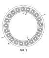
- the second stage 44 comprises a plurality of second stage compound planetary gear wheels 46, whose layout can best be appreciated from Figure 2 .
- the second stage compound planetary gears 46 comprise three sets of teeth, namely a central set 48 which mesh with a ring gear 50 mounted fixedly in the gearbox housing 22 and a pair of outer sets 52 having the same number of teeth as each other but a lower number of teeth than the gears 46 of the central set 48.
- the outer sets 52 are appropriately coupled to an annular output element 54 which is provided on its inner circumference 56 with a plurality of splines which engage a plurality of splines on the outer circumference 58 of the second leg portion 10.
- the number of planetary gears used in the first and second stages, and the ratio of gear teeth on the gears of each stage will be determined by the particular installation, for example the size of the installation and the speed reduction (and corresponding torque increase) required to drive the second wheel portion 10 at an appropriate speed.
- the motor 26 When steering of the nose wheel 2 is required, the motor 26 is energised. This causes rotation of the motor rotor 30 relative to the motor stator 26 and thereby relative to the first leg portion 6. This rotation is transmitted to the epicyclical gearing 38 through the drive gear 36.
- the gearing 38 reduces the rotational speed of the motor 22 and increases the torque correspondingly and transmits that torque to the second leg portion 10 through the splined engagement between the annular drive element 54 and the second leg portion 10. This rotation is transmitted to the third leg portion 16 which mounts the nose wheel(s) through the linkage 18.
- annular (toroidal) drive motor and annular (toroidal) gearing in the embodiment above may lead to a more compact steering arrangement, leading to reduced space requirements for the steering motor and gearing.
- using epicyclical gearing with a plurality of planetary gears coupled to the rotatable nose wheel leg portion may have the advantage, compared to a traditional arrangement, that the torque loads transmitted into the rotatable nose wheel leg portion are spread over a number of interfaces, rather than being concentrated at a single interface. This may again mean that a smaller and lighter gearbox may be used.
- the number of planetary gears used will depend on the particular application. As will be appreciated from Figure 2 , as the aircraft leg diameter increases, more torque may be required to drive the leg. However, because of the increase in diameter, more planetary gears may be arranged around the leg, which will distribute and share the load proportionately.
- gearing 38 illustrated is purely exemplary and that other gearing may be used.
- gearing it may be possible to use single stage gearing or non-compound gearing depending on the speed reduction/ torque increase required. What is important is that the gearing is toroidal and extends around the nose wheel leg.
Landscapes
- Engineering & Computer Science (AREA)
- Mechanical Engineering (AREA)
- Aviation & Aerospace Engineering (AREA)
- Power Engineering (AREA)
- Power Steering Mechanism (AREA)
- Retarders (AREA)
- Connection Of Motors, Electrical Generators, Mechanical Devices, And The Like (AREA)
Priority Applications (2)
| Application Number | Priority Date | Filing Date | Title |
|---|---|---|---|
| EP14275213.8A EP3006332A1 (fr) | 2014-10-08 | 2014-10-08 | Système d'orientation d'un train d'atterrissage avant |
| US14/878,141 US20160101847A1 (en) | 2014-10-08 | 2015-10-08 | Nose wheel steering |
Applications Claiming Priority (1)
| Application Number | Priority Date | Filing Date | Title |
|---|---|---|---|
| EP14275213.8A EP3006332A1 (fr) | 2014-10-08 | 2014-10-08 | Système d'orientation d'un train d'atterrissage avant |
Publications (1)
| Publication Number | Publication Date |
|---|---|
| EP3006332A1 true EP3006332A1 (fr) | 2016-04-13 |
Family
ID=51662010
Family Applications (1)
| Application Number | Title | Priority Date | Filing Date |
|---|---|---|---|
| EP14275213.8A Withdrawn EP3006332A1 (fr) | 2014-10-08 | 2014-10-08 | Système d'orientation d'un train d'atterrissage avant |
Country Status (2)
| Country | Link |
|---|---|
| US (1) | US20160101847A1 (fr) |
| EP (1) | EP3006332A1 (fr) |
Cited By (1)
| Publication number | Priority date | Publication date | Assignee | Title |
|---|---|---|---|---|
| EP3848280A1 (fr) * | 2020-01-13 | 2021-07-14 | Goodrich Corporation | Systèmes et procédés d'orientation d'un train d'atterrissage avant |
Families Citing this family (1)
| Publication number | Priority date | Publication date | Assignee | Title |
|---|---|---|---|---|
| US10940941B2 (en) * | 2014-12-04 | 2021-03-09 | Borealis Technical Limited | Method for increasing aircraft effective value |
Citations (5)
| Publication number | Priority date | Publication date | Assignee | Title |
|---|---|---|---|---|
| GB2161123A (en) * | 1984-07-05 | 1986-01-08 | Dowty Rotol Ltd | Aircraft retractable and steerable undercarriages |
| EP2020379A2 (fr) * | 2007-07-24 | 2009-02-04 | Goodrich Actuation Systems Ltd. | Ensemble de train d'atterrissage |
| EP2107003A1 (fr) * | 2008-04-01 | 2009-10-07 | Goodrich Actuation Systems Ltd. | Agencement d'embrayage |
| GB2459714A (en) * | 2008-05-02 | 2009-11-04 | Ge Aviat Uk | Aircraft landing gear steering system |
| GB2511856A (en) | 2013-03-15 | 2014-09-17 | Goodrich Actuation Systems Ltd | Damping arrangement for aircraft landing gear, for example a nosewheel |
Family Cites Families (4)
| Publication number | Priority date | Publication date | Assignee | Title |
|---|---|---|---|---|
| US3211400A (en) * | 1964-04-15 | 1965-10-12 | Lionel Pacific Inc | Landing gear steering apparatus |
| US3391580A (en) * | 1965-04-19 | 1968-07-09 | Ozone Metal Products Corp | Nosewheel steering system |
| GB201001175D0 (en) * | 2010-01-26 | 2010-03-10 | Airbus Operations Ltd | Aircraft steering actuator |
| GB201201270D0 (en) * | 2012-01-26 | 2012-03-07 | Goodrich Actuation Systems Ltd | Nose-wheel steering actuator |
-
2014
- 2014-10-08 EP EP14275213.8A patent/EP3006332A1/fr not_active Withdrawn
-
2015
- 2015-10-08 US US14/878,141 patent/US20160101847A1/en not_active Abandoned
Patent Citations (5)
| Publication number | Priority date | Publication date | Assignee | Title |
|---|---|---|---|---|
| GB2161123A (en) * | 1984-07-05 | 1986-01-08 | Dowty Rotol Ltd | Aircraft retractable and steerable undercarriages |
| EP2020379A2 (fr) * | 2007-07-24 | 2009-02-04 | Goodrich Actuation Systems Ltd. | Ensemble de train d'atterrissage |
| EP2107003A1 (fr) * | 2008-04-01 | 2009-10-07 | Goodrich Actuation Systems Ltd. | Agencement d'embrayage |
| GB2459714A (en) * | 2008-05-02 | 2009-11-04 | Ge Aviat Uk | Aircraft landing gear steering system |
| GB2511856A (en) | 2013-03-15 | 2014-09-17 | Goodrich Actuation Systems Ltd | Damping arrangement for aircraft landing gear, for example a nosewheel |
Cited By (1)
| Publication number | Priority date | Publication date | Assignee | Title |
|---|---|---|---|---|
| EP3848280A1 (fr) * | 2020-01-13 | 2021-07-14 | Goodrich Corporation | Systèmes et procédés d'orientation d'un train d'atterrissage avant |
Also Published As
| Publication number | Publication date |
|---|---|
| US20160101847A1 (en) | 2016-04-14 |
Similar Documents
| Publication | Publication Date | Title |
|---|---|---|
| US9638302B2 (en) | Electric axle with a two gear transmission | |
| CN107921993B (zh) | 商用车转向系统 | |
| US11420511B2 (en) | Drive device for a vehicle axle of a two-track vehicle | |
| EP2020379B1 (fr) | Ensemble de train d'atterrissage | |
| US10316946B2 (en) | Two mode electric drive module with Ravigneaux gearset | |
| US11485226B2 (en) | Transmission device for a motor vehicle | |
| CA2954108C (fr) | Dispositif d'engrenages planetaires | |
| US20200086947A1 (en) | Bicycle having electric drive or auxiliary drive | |
| US20120309578A1 (en) | Arrangement For Driving A Vehicle Wheel With A Drive Motor | |
| CN103492763B (zh) | 用于力传递的设备 | |
| US20170198792A1 (en) | Driving assembly comprising a rolling differential | |
| US10641377B2 (en) | Compact multi-stage gear with a planetary gear and a strain wave gear adjacent to said multi-stage gear | |
| US20170051801A1 (en) | Actuating device for an electromechanically actuatable vehicle brake | |
| CN103832467A (zh) | 紧凑型电动助力转向管柱、管柱式电动助力转向器和汽车 | |
| US10618642B2 (en) | Power transmission system and an aircraft having a rotary wing | |
| EP3006332A1 (fr) | Système d'orientation d'un train d'atterrissage avant | |
| CN104908804A (zh) | 转向装置 | |
| CN203819033U (zh) | 一种用于电动汽车的动力总成装置 | |
| WO2016177494A1 (fr) | Système, notamment véhicule à changement de vitesses progressif qui peut être entraîné électriquement et/ou par la force musculaire | |
| CN104295675A (zh) | 一种二档电动车变速器总成 | |
| CN107477169A (zh) | 紧凑的行星齿轮传动装置 | |
| EP3317135A1 (fr) | Transmission finale pour véhicules motorisés industriels et agricoles | |
| CN114585551B (zh) | 车辆的机电转向系统的转向传动装置、车辆的机电转向系统 | |
| US10988021B2 (en) | In-wheel motor powertrain | |
| CN107701662B (zh) | 用于在蜗杆蜗轮组件中分配扭矩的装置和方法 |
Legal Events
| Date | Code | Title | Description |
|---|---|---|---|
| PUAI | Public reference made under article 153(3) epc to a published international application that has entered the european phase |
Free format text: ORIGINAL CODE: 0009012 |
|
| AK | Designated contracting states |
Kind code of ref document: A1 Designated state(s): AL AT BE BG CH CY CZ DE DK EE ES FI FR GB GR HR HU IE IS IT LI LT LU LV MC MK MT NL NO PL PT RO RS SE SI SK SM TR |
|
| AX | Request for extension of the european patent |
Extension state: BA ME |
|
| STAA | Information on the status of an ep patent application or granted ep patent |
Free format text: STATUS: THE APPLICATION IS DEEMED TO BE WITHDRAWN |
|
| 18D | Application deemed to be withdrawn |
Effective date: 20161014 |