EP2020586A2 - Stützvorrichtung für eine Sprengladung eines Penetrators - Google Patents
Stützvorrichtung für eine Sprengladung eines Penetrators Download PDFInfo
- Publication number
- EP2020586A2 EP2020586A2 EP08013492A EP08013492A EP2020586A2 EP 2020586 A2 EP2020586 A2 EP 2020586A2 EP 08013492 A EP08013492 A EP 08013492A EP 08013492 A EP08013492 A EP 08013492A EP 2020586 A2 EP2020586 A2 EP 2020586A2
- Authority
- EP
- European Patent Office
- Prior art keywords
- charge
- penetrator
- partition
- support device
- shell
- Prior art date
- Legal status (The legal status is an assumption and is not a legal conclusion. Google has not performed a legal analysis and makes no representation as to the accuracy of the status listed.)
- Granted
Links
- 239000002360 explosive Substances 0.000 title claims description 62
- 230000000977 initiatory effect Effects 0.000 claims abstract description 22
- 239000000463 material Substances 0.000 claims abstract description 14
- 238000005192 partition Methods 0.000 claims description 62
- 238000005474 detonation Methods 0.000 claims description 28
- 230000015572 biosynthetic process Effects 0.000 claims description 12
- 239000012791 sliding layer Substances 0.000 claims description 8
- 238000004049 embossing Methods 0.000 claims description 3
- 238000007493 shaping process Methods 0.000 claims description 3
- 239000012634 fragment Substances 0.000 claims 1
- 238000005755 formation reaction Methods 0.000 description 11
- 206010041662 Splinter Diseases 0.000 description 9
- 230000000694 effects Effects 0.000 description 8
- 230000001133 acceleration Effects 0.000 description 7
- 239000008188 pellet Substances 0.000 description 7
- 229910052751 metal Inorganic materials 0.000 description 5
- 239000002184 metal Substances 0.000 description 5
- 150000002739 metals Chemical class 0.000 description 4
- 238000006073 displacement reaction Methods 0.000 description 3
- 238000000034 method Methods 0.000 description 3
- 239000004033 plastic Substances 0.000 description 3
- 229920003023 plastic Polymers 0.000 description 3
- 230000035939 shock Effects 0.000 description 3
- RTAQQCXQSZGOHL-UHFFFAOYSA-N Titanium Chemical compound [Ti] RTAQQCXQSZGOHL-UHFFFAOYSA-N 0.000 description 2
- 230000008901 benefit Effects 0.000 description 2
- 230000000149 penetrating effect Effects 0.000 description 2
- 230000008569 process Effects 0.000 description 2
- 230000009467 reduction Effects 0.000 description 2
- 239000010936 titanium Substances 0.000 description 2
- 229910052719 titanium Inorganic materials 0.000 description 2
- RYGMFSIKBFXOCR-UHFFFAOYSA-N Copper Chemical compound [Cu] RYGMFSIKBFXOCR-UHFFFAOYSA-N 0.000 description 1
- 239000004809 Teflon Substances 0.000 description 1
- 229920006362 Teflon® Polymers 0.000 description 1
- 230000009471 action Effects 0.000 description 1
- 238000004026 adhesive bonding Methods 0.000 description 1
- 239000011449 brick Substances 0.000 description 1
- 230000008859 change Effects 0.000 description 1
- 229910052802 copper Inorganic materials 0.000 description 1
- 239000010949 copper Substances 0.000 description 1
- 238000005336 cracking Methods 0.000 description 1
- 230000006378 damage Effects 0.000 description 1
- 230000001934 delay Effects 0.000 description 1
- 230000003111 delayed effect Effects 0.000 description 1
- 230000007613 environmental effect Effects 0.000 description 1
- 238000002474 experimental method Methods 0.000 description 1
- 238000005304 joining Methods 0.000 description 1
- 239000010410 layer Substances 0.000 description 1
- 238000004519 manufacturing process Methods 0.000 description 1
- 238000009304 pastoral farming Methods 0.000 description 1
- 230000002787 reinforcement Effects 0.000 description 1
- 239000011435 rock Substances 0.000 description 1
- 230000035945 sensitivity Effects 0.000 description 1
- 238000004513 sizing Methods 0.000 description 1
- 230000008646 thermal stress Effects 0.000 description 1
- 238000003466 welding Methods 0.000 description 1
Images



Classifications
-
- F—MECHANICAL ENGINEERING; LIGHTING; HEATING; WEAPONS; BLASTING
- F42—AMMUNITION; BLASTING
- F42B—EXPLOSIVE CHARGES, e.g. FOR BLASTING, FIREWORKS, AMMUNITION
- F42B1/00—Explosive charges characterised by form or shape but not dependent on shape of container
- F42B1/02—Shaped or hollow charges
- F42B1/024—Shaped or hollow charges provided with embedded bodies of inert material
-
- F—MECHANICAL ENGINEERING; LIGHTING; HEATING; WEAPONS; BLASTING
- F42—AMMUNITION; BLASTING
- F42B—EXPLOSIVE CHARGES, e.g. FOR BLASTING, FIREWORKS, AMMUNITION
- F42B12/00—Projectiles, missiles or mines characterised by the warhead, the intended effect, or the material
- F42B12/02—Projectiles, missiles or mines characterised by the warhead, the intended effect, or the material characterised by the warhead or the intended effect
- F42B12/04—Projectiles, missiles or mines characterised by the warhead, the intended effect, or the material characterised by the warhead or the intended effect of armour-piercing type
-
- F—MECHANICAL ENGINEERING; LIGHTING; HEATING; WEAPONS; BLASTING
- F42—AMMUNITION; BLASTING
- F42B—EXPLOSIVE CHARGES, e.g. FOR BLASTING, FIREWORKS, AMMUNITION
- F42B12/00—Projectiles, missiles or mines characterised by the warhead, the intended effect, or the material
- F42B12/02—Projectiles, missiles or mines characterised by the warhead, the intended effect, or the material characterised by the warhead or the intended effect
- F42B12/04—Projectiles, missiles or mines characterised by the warhead, the intended effect, or the material characterised by the warhead or the intended effect of armour-piercing type
- F42B12/10—Projectiles, missiles or mines characterised by the warhead, the intended effect, or the material characterised by the warhead or the intended effect of armour-piercing type with shaped or hollow charge
-
- F—MECHANICAL ENGINEERING; LIGHTING; HEATING; WEAPONS; BLASTING
- F42—AMMUNITION; BLASTING
- F42B—EXPLOSIVE CHARGES, e.g. FOR BLASTING, FIREWORKS, AMMUNITION
- F42B12/00—Projectiles, missiles or mines characterised by the warhead, the intended effect, or the material
- F42B12/02—Projectiles, missiles or mines characterised by the warhead, the intended effect, or the material characterised by the warhead or the intended effect
- F42B12/20—Projectiles, missiles or mines characterised by the warhead, the intended effect, or the material characterised by the warhead or the intended effect of high-explosive type
- F42B12/201—Projectiles, missiles or mines characterised by the warhead, the intended effect, or the material characterised by the warhead or the intended effect of high-explosive type characterised by target class
- F42B12/204—Projectiles, missiles or mines characterised by the warhead, the intended effect, or the material characterised by the warhead or the intended effect of high-explosive type characterised by target class for attacking structures, e.g. specific buildings or fortifications, ships or vehicles
Definitions
- the invention relates to a support device for an explosive charge of a penetrator, the explosive charge consists of at least one front and one rear part charge, which are arranged inside the shell of the penetrator behind the other, wherein between the part charges a cross-section of the explosive charge covering and attached to the shell of the penetrator Partition is arranged and the ignition of the explosive charge emanates from the rear part of the charge.
- Penetrators are active systems which, due to their structural design, are suitable for penetrating resistant structures such as building walls made of brick or concrete or even rock.
- penetrator equipped with a hollow charge When combating such structures by a penetrator equipped with a hollow charge, the effect of the directed hollow charge is no longer in the foreground. Rather, it is of interest that the penetrator after penetrating the structure is still able to unfold in the space behind the structure as high as possible Blast- and / or splintering performance. Otherwise, the mission can not be adequately fulfilled.
- the invention is based on the problem that on the one hand high-strength and thick structures must be perforated. This requires fast and slim long penetrators with a correspondingly long explosive charge.
- the penetrator and thus also the explosive charge during perforation undergoes a very high negative acceleration, which causes the explosive charge to the penetrator tip moves as far as allow the cavities present in the Penetratorspitze. In particular, the cavity located in front of the shaped charge liner is affected. This movement of the explosive charge towards the penetrator tip and thus away from the ignition device involves the risk that distances in particular from the booster charge to Explosive charge become too large and a safe initiation of the explosive charge is no longer guaranteed.
- a support of the explosive charge by the usually made of soft and ductile metal insert of the shaped charge fails because of their insufficient resistance to the accelerations occurring.
- the load of the insert through the long explosive column in the penetrator would lead to an inversion of the insert, at most until it rests against the inner wall of the shell.
- the invention is based on the idea to find a suitable support of the explosive charge with respect to the acceleration forces occurring.
- the DE 695 09 332 T2 describes a projectile for the destruction of hard targets.
- several explosive charges are arranged, which are equipped with their own ignition devices.
- the ignition of the explosive charges inevitably takes place serially from behind Forward.
- the individual explosive charges are partitioned off from one another by partitions.
- the partitions are used to support the individual explosive charges with each other and are in terms of sizing and the choice of materials such that when initiating one of the explosive charges in any case, the shell is destroyed before the partition. Only in this way, at the same time a blast or splintering effect of the individual explosive charges and at the same time a propulsion of the remaining Penetratorteils be achieved. However, the achievable effect is limited to the implementable amount of explosive each successive detonated charges. A simultaneous initiation of all individual explosive charges is not possible hereby. Thus, this embodiment of a support for solving the above problems is not suitable.
- the invention has for its object to find a support for the explosive charge of a penetrator, which avoids the problems mentioned and allows the deployment of the power of the entire explosive charge of the penetrator at a desired time.
- the solution of the problem according to the present invention is that at least one serving as a supporting device partition is formed and / or made of such a material that upon initiation of the rear partial charge in each case, the partition wall is disassembled in front of the shell.
- the partition wall is not an obstacle to the detonation front, so that the entire partial charges are completely detonated.
- a sliding layer is advantageously arranged between the front part charge and the shell, which extends from the partition to the top of the Penetrators extends and which upon impact of the penetrator on the target, the movement of the front part of the charge into the tip of the penetrator supported.
- the sliding layer may also have an embossing on the surface adjacent to the shell, whereby splinters of desired size can be generated.
- a plurality of spaced-apart partitions may be provided in the explosive charge, which support the entire explosive charge and only the foremost small part charge is held by the insert. In this case, no sliding layer is used.
- the explosive charge of a penetrator is divided into at least two partial charges, which are separated by a respective weaker against the shell partition designed, the partitions are firmly connected to the shell to be able to support the onloading partial charge.
- the support must of course be able to hold only this part of the explosive charge.
- the partition in the direction of the rear partial charge is simply or multiply convex, wherein the formation of the partition can be made, for example, conical or hemispherical.
- the function of the hooking of the partition in the shell is supported.
- the inherently elastic explosive charge column is axially stabilized in itself.
- the dividing wall has a detonation waveguide in the respective central area.
- This can be realized as a separate component or else in that the partition has a greater thickness in the respective central region than in the outer region. so that can focus the detonation wave striking the bulkhead from behind onto the next section of the explosive charge.
- auxiliary charge is integrated in the partition wall. These may be arranged as a circle around the center of the insert around as evenly distributed individual charges. An embodiment in the form of a single annular charge can just as well be used. The initiation takes place by means of the detonation wave coming from behind onto the dividing wall.
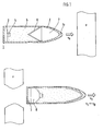
- FIG. 1 For understanding the processes occurring at the moment of the impact of a penetrator on a target Z is described in the FIG. 1 in the upper half of a penetrator 1 before the target passage and in the lower half of a penetrator after the target passage in each case in a sectional view.
- the ignition system 3 Within the shell 2 of the penetrator is located at the rear of the ignition system 3, which ignites the explosive charge 5 in the case of initiation on the booster charge 4. It is assumed in the example of only one explosive charge within the shell 2 of the penetrator 1 .
- the insert 6 With the explosive charge 5, the insert 6 is positively connected, so that explosive charge and insert together form a shaped charge with effect in the direction of the tip 2a of the penetrator.
- the insert is made of relatively soft and ductile copper and is therefore unable to withstand higher loads. It is also assumed that the envelope of the penetrator is long and slender.
- the penetrator hits the target Z at a speed v 0 , perforates it and then moves on at the significantly reduced speed v 1 . Due to the enormous delay that occurs, the pressure of the explosive charge 5 on the insert 6 can become so great that it comes loose from its holder and inverts in the direction of the tip 2a. The explosive charge slides together with the deforming insert forward until the previously existing cavity 7, which actually serves the formation of the shaped charge spine, is filled. With lower delays different intermediate states are possible. This creates on the back of the explosive charge 5, a new cavity 8, whose volume is about as large as the volume loss of the front cavity 7.
- a structurally offering change in the form of a reinforced support of the insert on the shell 2 is not a solution, since it would be a significant reduction in performance of the shaped charge would be connected.
- the explosive charge 5 is off FIG. 1 divided into two or more partial charges HE1, ..., HE4 whose Loads so each serving as supports dividing walls A, A1, ..., A3 is divided.
- the number of dividing walls depends on the length of the penetrator and on the expected negative accelerations in use.
- the partitions cover the entire inner cross section of the shell 2 of the penetrator. With regard to the shape of a variety of configurations are possible.
- the partitions do not pose an obstacle to the shockwave entering the bulkhead after initiation of the explosive charge (generated by the detonation front of the explosive charge) as the shockwave front continues within the bulkhead materials and triggers a new detonation on the exit side in the explosive charge.
- FIG. 2 initially the cone or dome-shaped partition shown.
- Other examples are in the FIGS. 4 and 5 shown without the design of the partition would be limited to the examples shown.
- the dividing walls A, A1,..., A3 used as supports open in the direction of the insert 6, so that the edge of the dividing wall can be supported in each case against the shell 2 of the penetrator and can catch it.
- the entire, in itself very elastic explosive charge is stabilized by the partitions axially in itself.
- the material for the partitions high strength and low density metals such as titanium or other materials having similar properties are well suited.
- FIG. 3 Especially with long penetrators, which are exposed to high negative accelerations, offers a solution, as in the FIG. 3 is shown. It is deliberately omitted to support the entire explosive charge. Instead, the explosive charge is divided by means of a correspondingly designed partition A into two different sized partial charges HE1 and HE2. Thus, only the smaller rear partial charge HE1 is supported independently of the front partial charge HE2. So the partition A does not have to be made particularly massive. Rather, a constructive secure support must be achieved. This is achieved for example by a circumferential reinforcement of the edge of the partition. As a connection to the shell itself usually sufficient gluing, welding or other joining technique with similar strength.
- the front partial charge HE2 due to strong negative acceleration slips forward until it rests against the inner wall of the tip 2a of the penetrator, it is expedient to support this process by means of a thin sliding layer 8.
- This sliding layer 8 usually clothes the interior of the penetrator from the partition wall A to the tip 2a.
- Suitable materials for this overlay are plastics with a low coefficient of friction on the surface such as Teflon.
- the sliding layer may have on its outer surface an embossing, which supports the formation of splitters of desired size upon detonation of the partial charge HE2.
- the initiation of the rear partial charge HE1 via the booster charge takes place. since the partition wall A supports this partial charge HE1 in the target passage, a reliable initiation of this partial charge HE1 is ensured. Due to the displacement into the previously existing cavity 7a in the tip 2a and the simultaneous formation of a further cavity 7b behind the partial charge HE2, the front partial charge HE2 now has a distance x from the dividing wall A. This distance is so great that it can not be bridged by a booster charge 4. However, since the rear partial charge HE1 can be safely initiated, the detonation shock generated by this partial charge for the inevitable follow-up initiation of the front partial charge HE2 over the Partition A off.
- the partition allows this type of ignition by their nature in terms of dimensioning and the choice of material. Both factors are chosen so that in each case the partition A is decomposed in front of the shell 2. Thus, the ignition takes place prior to the disassembly of the shell 2.
- the effect of the initiated partial charges HE1 and HE2 in the target is then no longer the spike formation of a shaped charge as shown in FIG FIG. 3 upper half, but the radial splitter delivery.
- splinter generation is limited only in the area of the cavity 7b. For this, however, the area of the cavity 7a existing before the displacement of the partial charge HE2 is included in the splinter formation. Overall, there is thus no reduction in performance due to the shift.
- the two partial charges do not necessarily consist of the same explosive charge. In this advantageous manner, a vote between initiation sensitivity and performance can be made.
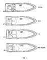
- FIG. 4 It is shown how the design of the partition A can influence the support of the initiation.
- Various examples are in the four drawings of FIG. 4 illustrated, other embodiments are of course conceivable.
- the top example corresponds to the configuration from the FIG. 3 ,
- the partition may be designed as a flat plate A10, which acts at short distances x as a flying plate. At longer distances natural splinters form. Splinter formation can be influenced by a further material layer applied to the dividing wall.
- the two lower drawings of the FIG. 5 show, however, that the same principle is also applicable to penetrators with at least one partition A.
- the partition wall A is fitted in its central region with a detonation shaft 9 or the partition A itself is formed in its central part so that the deflection of the detonation front takes place as in a detonation 9.
- the with a detonation shaft 9 supplemented partition A is conveniently placed in the vicinity of the insert.
- at least the edge of the partition is inclined towards the tip of the penetrator.
- Other partitions in the above-described design can also be used depending on the length of the penetrator.
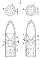
- the course of the detonation fronts 21, 22, 23 and 31, 32, 33 is shown in dashed lines. In both cases, the detonation front approximately perpendicular to the insert 6, so that the optimum performance can be implemented.
- the in the lower drawing of the FIG. 5 illustrated embodiment has particularly advantageous properties.
- the material selection and shaping of this partition A is achieved that, exploiting the low propagation velocities, such as in plastics from 1000 to 2000 m / s, the detonation front is locally delayed differently, which ultimately the formation of the detonation front is achieved.
- the formation of the detonation front can be made largely flexible.
- pellets ie compact explosive charges
- FIG. 6 An extension of the lower drawing of the FIG. 5 illustrated embodiment is in two exemplary variants in the FIG. 6 played.
- pellets ie compact explosive charges
- the advantages of the pellets can be utilized.
- front partial charge HE2 detonation fronts emanating from the pellets form, which strike the insert 6 approximately perpendicularly.
- the section A '- B' shows an example of a possible arrangement of the pellets in the partition A. It should be noted, however, that on the one hand enough pellets are provided to achieve the most homogeneous detonation front and on the other hand, the strength of the partition is not limited too much.
- FIG. 6 Another embodiment is in the lower drawing of FIG. 6 shown.
- a single annular compact explosive charge 10b used at the location of each arranged on a circle pellets according to the upper drawing of FIG. 6 .
- the annular explosive charge may be arranged in or on the partition wall A.
Landscapes
- Engineering & Computer Science (AREA)
- General Engineering & Computer Science (AREA)
- Chemical & Material Sciences (AREA)
- Combustion & Propulsion (AREA)
- Portable Nailing Machines And Staplers (AREA)
- Crushing And Pulverization Processes (AREA)
Abstract
Description
- Die Erfindung betrifft eine Stützvorrichtung für eine Sprengladung eines Penetrators , dessen Sprengladung aus wenigstens einer vorderen und einer rückwärtigen Teilladung besteht, welche innerhalb der Hülle des Penetrators hintereinander angeordnet sind, wobei zwischen den Teilladungen eine den Querschnitt der Sprengladung abdeckende und an der Hülle des Penetrators befestigte Trennwand angeordnet ist und die Zündung der Sprengladung von der hinteren Teilladung ausgeht.
- Penetratoren sind Wirksysteme, die aufgrund ihres konstruktiven Aufbaus geeignet sind, widerstandsfähige Strukturen wie beispielsweise Gebäudewände aus Ziegel oder Beton oder auch Fels zu durchdringen. Bei der Bekämpfung derartiger Strukturen durch einen mit einer Hohlladung ausgestatteten Penetrator steht die Wirkung der gerichteten Hohlladung nicht mehr unbedingt im Vordergrund. Vielmehr ist es von Interesse, dass der Penetrator nach dem Durchdringen der Struktur noch in der Lage ist, im Raum hinter der Struktur eine möglichst hohe Blast- und/oder Splitterleistung zu entfalten. Anderenfalls kann die Mission nur unzureichend erfüllt werden.
- Der Erfindung liegt nun das Problem zugrunde, dass einerseits hochfeste und dicke Strukturen perforiert werden müssen. Dies erfordert schnelle und schlanke lange Penetratoren mit einer entsprechend langen Sprengladung. Andererseits erfährt der Penetrator und damit auch die Sprengladung beim Perforationsvorgang eine sehr hohe negative Beschleunigung, die dazu führt, dass sich die Sprengladung zur Penetratorspitze hin bewegt soweit dies die in der Penetratorspitze vorhandenen Hohlräume zulassen. Insbesondere ist der vor der Hohlladungseinlage befindliche Hohlraum davon betroffen. Diese Bewegung der Sprengladung hin zur Penetratorspitze und damit weg von der Zündeinrichtung birgt die Gefahr, dass Abstände insbesondere von der Verstärkerladung zur Sprengladung zu groß werden und eine sichere Initiierung der Sprengladung nicht mehr gewährleistet ist.
- Eine Verklebung der Sprengladung mit der Penetratorhülle verbietet sich, da ausschließlich unempfindliche kunststoffgebundene Sprengstoffe Verwendung finden. Diese haben gegenüber Metallen einen wesentlich höheren Ausdehnungskoeffizienten, so dass bei üblichen Umwelt-, Temperaturbelastungen die Klebung zur Rissbildung in der Sprengladung führen würde. Ein konventioneller Sprengstoff hingegen würde aufgrund der hohen Schockbelastung frühzeitig und ungewollt detonieren.
- Eine Abstützung der Sprengladung durch die üblicherweise aus weichem und duktilem Metall bestehende Einlage der Hohlladung scheitert an deren unzureichenden Widerstandsfähigkeit gegen die auftretenden Beschleunigungen. Die Belastung der Einlage durch die lange Sprengstoffsäule im Penetrator würde zu einer Umstülpung der Einlage, maximal bis zur Anlage an der Innenwand der Hülle führen.
- Der Erfindung liegt die Idee zugrunde eine geeignete Abstützung der Sprengladung gegenüber den auftretenden Beschleunigungskräften zu finden.
- Aus der
DE 199 17 144 B4 ist ein Kombinationswirksystem bekannt geworden, welches zwischen verschiedenen Wirkungsmodi, insbesondere Hohlladung, Blast/Splitterladung oder Penetrator, umschaltbar ist. Diese Patentschrift beschreibt die entsprechende Ausgestaltungen, bietet jedoch keine Lösung für die genannten Probleme. - Die
DE 695 09 332 T2 beschreibt ein Geschoss für die Zerstörung von harten Zielen. In Längsrichtung eines Penetratorgehäuses sind hierbei mehrere Sprengladungen angeordnet, welche mit eigenen Zündeinrichtungen ausgestattet sind. Die Zündung der Sprengladungen erfolgt zwangsläufig seriell von hinten nach vorne. Die einzelnen Sprengladungen sind durch Trennwände voneinander abgeschottet. Die Trennwände dienen der Abstützung der einzelnen Sprengladungen untereinander und sind hinsichtlich der Dimensionierung und der Materialauswahl derart beschaffen, dass bei der Initiierung einer der Sprengladungen in jedem Fall die Hülle vor der Trennwand zerstört wird. Nur auf diese Weise kann gleichzeitig eine Blast- oder Splitterwirkung der einzelnen Sprengladungen und gleichzeitig ein Vortrieb des verbleibenden Penetratorteils erzielt werden. Die erzielbare Wirkung beschränkt sich jedoch auf die umsetzbare jeweilige Menge an Sprengstoff der einzelnen nacheinander gezündeten Sprengladungen. Eine gleichzeitige Initiierung aller einzelnen Sprengladungen ist hiermit nicht möglich. Somit ist diese Ausführungsform einer Abstützung zur Lösung der genannten Probleme nicht geeignet. - Der Erfindung liegt die Aufgabe zugrunde, eine Abstützung für die Sprengladung eines Penetrators zu finden, die die genannten Probleme vermeidet und die Entfaltung der Leistung der gesamten Sprengladung des Penetrators zu einem gewollten Zeitpunkt ermöglicht.
- Die Lösung der Aufgabe besteht gemäß der vorliegenden Erfindung darin, dass wenigstens eine als Stützvorrichtung dienende Trennwand so geformt ist und/oder aus einem solchen Material besteht, dass bei Initiierung der hinteren Teilladung in jedem Fall die Trennwand vor der Hülle zerlegt wird. Somit stellt die Trennwand kein Hindernis für die Detonationsfront dar, so dass die gesamten Teilladungen vollständig durchdetonieren.
- Bei den Ladungen, bei denen lediglich eine Trennwand zum Einsatz kommt und bei denen der vordere Teil der Sprengladung nicht abgestützt werden soll, ist in vorteilhafter Weise zwischen der vorderen Teilladung und der Hülle eine Gleitschicht angeordnet, welche sich von der Trennwand bis in die Spitze des Penetrators erstreckt und welche beim Aufprall des Penetrators auf das Ziel die Bewegung der vorderen Teilladung in die Spitze des Penetrators hinein unterstützt. Die Gleitschicht kann auch eine Prägung an der an der Hülle anliegenden Oberfläche aufweisen, womit Splitter gewünschter Größe erzeugbar sind.
- Darüber hinaus können in der Sprengladung mehrere zueinander beabstandet angeordnete Trennwände vorgesehen sein, wobei diese die gesamte Sprengladung abstützen und nur die vorderste kleine Teilladung von der Einlage gehalten wird . In diesem Fall kommt keine Gleitschicht zum Einsatz.
- Somit ist die Sprengladung eines Penetrators in wenigstens zwei Teilladungen aufgeteilt, die durch jeweils eine gegenüber der Hülle schwächer ausgelegten Trennwand voneinander getrennt sind, wobei die Trennwände mit der Hülle fest verbunden sind um die darauf lastende Teilladung abstützen zu können. Die Abstützung muss natürlich nur noch diesen Teil der Sprengladung halten können.
- In vorteilhafter Weise ist die Trennwand in Richtung der rückwärtigen Teilladung einfach oder mehrfach konvex geformt, wobei die Formung der Trennwand beispielsweise kegelförmig oder halbkugelförmig ausgeführt sein kann. Dadurch wird mit zunehmendem Druck der entsprechenden Teilladung auf die Trennwand die Funktion des Verhakens der Trennwand in der Hülle unterstützt. Gleichzeitig wird die in sich elastische Sprengladungssäule axial in sich stabilisiert.
- Als günstig erweist es sich hierbei, als Material für die Trennwände Metalle mit hoher Festigkeit und geringer Dichte, wie beispielsweise Titan, auszuwählen. Andere Materialien mit ähnlichen Eigenschaften sind bei der Auswahl nicht ausgeschlossen.
- Nach einer vorteilhaften Ausführungsform weist die Trennwand im jeweiligen zentralen Bereich einen Detonationswellenlenker auf. Dieser kann als eigenes Bauteil realisiert sein oder auch dadurch, dass die Trennwand im jeweiligen zentralen Bereich eine größere Dicke als im äußeren Bereich aufweist. damit kann die von hinten auf die Trennwand auftreffende Detonationswelle auf die nächste Sektion der Sprengladung fokussiert werden.
- Es hat sich als günstig erwiesen, wenn in der Trennwand wenigstens eine Hilfsladung integriert ist. Diese können als auf einem Kreis um das Zentrum der Einlage herum als gleichmäßig verteilte Einzelladungen angeordnet sein. Ebenso gut kann eine Ausführungsform in Gestalt einer einzigen ringförmigen Ladung Verwendung finden. Die Initiierung erfolgt dabei mittels der von hinten auf die Trennwand auflaufenden Detonationswelle.
- Alternativ hierzu ist es auch möglich, die Initiierung zweier benachbarter Teilladungen mit Hilfe der in der Trennwand integrierten Hilfsladung gleichzeitig und unabhängig von sonstigen Zündeinrichtungen durchzuführen.
- Ausführungsbeispiele der Erfindung sind in der Zeichnung schematisch vereinfacht dargestellt und werden im Folgenden näher beschrieben. Es zeigen:
-
Fig.1 : einen Penetrator mit Hohlladung vor und nach dem Zieldurchgang, -
Fig.2 : einen Penetrator mit einer oder mehreren Abstützungen, -
Fig. 3 : die Wirkung einer Abstützung in einem Penetrator, -
Fig. 4 : verschiedene Ausführungsformen von Abstützungen, -
Fig. 5 : Beispiele für Abstützungen mit DWL-Funktion, -
Fig. 6 : Abstützungen mit integrierter Initiierung. - Zum Verständnis der im Moment des Aufpralls eines Penetrators auf ein Ziel Z ablaufenden Vorgänge ist in der
Figur 1 in der oberen Hälfte ein Penetrator 1 vor dem Zieldurchgang und in der unteren Hälfe ein Penetrator nach dem Zieldurchgang jeweils in einem Schnittbild dargestellt. Innerhalb der Hülle 2 des Penetrators befindet sich am Heck das Zündsystem 3, welches im Fall der Initiierung über die Verstärkerladung 4 die Sprengladung 5 zündet. Es wird im Beispiel von nur einer Sprengladung innerhalb der Hülle 2 des Penetrators 1 ausgegangen. Mit der Sprengladung 5 ist die Einlage 6 formschlüssig verbunden, so dass Sprengladung und Einlage zusammen eine Hohlladung mit Wirkung in Richtung der Spitze 2a des Penetrators bilden. Typischerweise besteht die Einlage aus relativ weichem und duktilem Kupfer und ist damit nicht in der Lage höhere Lasten aufzunehmen. Es wird außerdem davon ausgegangen, dass die Hülle des Penetrators lang und schlank ausgeführt ist. - Der Penetrator trifft mit einer Geschwindigkeit v0 auf das Ziel Z auf, perforiert dieses und bewegt sich dann mit der erheblich reduzierten Geschwindigkeit v1 weiter. Aufgrund der dabei auftretenden enormen Verzögerung kann der Druck der Sprengladung 5 auf die Einlage 6 so groß werden, dass die sich aus ihrer Halterung löst und sich in Richtung der Spitze 2a umstülpt. Dabei rutscht die Sprengladung zusammen mit der sich deformierenden Einlage nach vorne bis der vorher vorhandene Hohlraum 7, der eigentlich der Ausbildung des Hohlladungsstachels dient, aufgefüllt ist. Bei geringeren Verzögerungen sind verschiedene Zwischenzustände möglich. Dabei entsteht auf der Rückseite der Sprengladung 5 ein neuer Hohlraum 8, dessen Volumen etwa so groß ist wie der Volumenverlust des frontseitigen Hohlraumes 7.
- Eine sich konstruktiv anbietende Änderung in Form einer verstärkten Abstützung der Einlage an der Hülle 2 stellt keine Lösung dar, da damit eine erheblich Leistungsminderung der Hohlladung verbunden wäre.
- In der
Figur 2 ist das Prinzip des Vorschlags zur Lösung des Problems dargestellt, welches die vorgenannten Nachteile vermeidet. Demnach wird die Sprengladung 5 ausFigur 1 in zwei oder mehrere Teilladungen HE1, ..., HE4 unterteilt, deren Lasten damit jeweils auf als Abstützungen dienende Trennwände A, A1, ... , A3 aufgeteilt wird. Die Anzahl der Trennwände hängt von der Länge des Penetrators und von den im Einsatz zu erwartenden negativen Beschleunigungen ab. Die Trennwände decken dabei den gesamten Innenquerschnitt der Hülle 2 des Penetrators ab. Hinsichtlich der Formgebung sind unterschiedlichste Ausgestaltungen möglich. Die Trennwände stellen für die nach der Initiierung der Sprengladung in die Trennwand einlaufende Stoßwelle (erzeugt von der Detonationsfront der Sprengladung) kein Hindernis dar, da sich die Stoßwellenfront innerhalb der Materialien der Trennwand fortsetzt und auf der Austrittsseite in der Sprengladung eine neue Detonation auslöst. - Als Beispiele für mögliche Formen ist in der
Figur 2 zunächst die kegel- oder kalottenförmige Trennwand dargestellt. Weitere Beispiele sind in denFiguren 4 und5 dargestellt ohne dass die Gestaltung der Trennwand auf die gezeigten Beispiele begrenzt wäre. - In vorteilhafter Weise öffnen sich die als Abstützungen genutzten Trennwände A, A1, ..., A3 in Richtung der Einlage 6, so dass sich der Rand der Trennwand jeweils gegen die Hülle 2 des Penetrators abstützen und verhaken kann. Außerdem wird die gesamte, an sich sehr elastische Sprengladung durch die Trennwände axial in sich stabilisiert. Als Material für die Trennwände sind Metalle mit hoher Festigkeit und geringer Dichte, wie beispielsweise Titan, oder auch andere Werkstoffe mit ähnlichen Eigenschaften gut geeignet.
- Besonders bei langen Penetratoren, die hohen negativen Beschleunigungen ausgesetzt werden, bietet sich eine Lösung an, wie sie in der
Figur 3 dargestellt ist. Dabei wird bewusst darauf verzichtet, die gesamte Sprengladung abzustützen. Stattdessen wird die Sprengladung mit Hilfe einer entsprechend ausgelegten Trennwand A in zwei unterschiedlich große Teilladungen HE1 und HE2 aufgeteilt. Somit wird nur noch die kleinere hintere Teilladung HE1 unabhängig von der vorderen Teilladung HE2 abgestützt. Damit muss die Trennwand A auch nicht besonders massiv ausgestaltet werden. Vielmehr muss konstruktiv eine sichere Abstützung erreicht werden. Dies wird beispielsweise durch eine umlaufende Verstärkung des Randes der Trennwand erreicht. Als Verbindung zur Hülle selbst genügt in der Regel eine Klebung, eine Schweißung oder eine andere Verbindungstechnik mit ähnlicher Festigkeit. - Da es vorgesehen ist, dass die vordere Teilladung HE2, wie in der unteren Hälfte der
Figur 3 dargestellt, in Folge starker negativer Beschleunigung bis zur Anlage an der Innenwand der Spitze 2a des Penetrators nach vorne rutscht, ist es zweckmäßig diesen Vorgang mit Hilfe einer dünnen Gleitschicht 8 zu unterstützen. Diese Gleitschicht 8 kleidet üblicherweise den Innenraum des Penetrators von der Trennwand A bis zur Spitze 2a aus. Als Material für diese Gleitschicht eignen sich Kunststoffe mit einem niedrigen Reibungskoeffizienten an der Oberfläche wie beispielsweise Teflon. Somit können Reibungen an der Oberfläche der Innenwand weitgehend vermieden werden, so dass die Möglichkeit einer ungewollten frühzeitigen Initiierung der Teilladung HE2 vermieden werden kann. Zusätzlich kann die Gleitschicht an ihrer äußeren Oberfläche eine Prägung aufweisen, welche bei Detonation der Teilladung HE2 die Bildung von Splittern gewünschter Größe unterstützt. - Nach dem Zieldurchgang erfolgt ausgehend von heckseitig montierten Zündsystem 3 die Initiierung der hinteren Teilladung HE1 über die Verstärkerladung. da die Trennwand A diese Teilladung HE1 beim Zieldurchgang abstützt ist eine sichere Initiierung dieser Teilladung HE1 gewährleistet. Die vordere Teilladung HE2 weist aufgrund der Verschiebung in den vorher bestehenden Hohlraum 7a in der Spitze 2a und der gleichzeitigen Ausbildung eines weiteren Hohlraumes 7b hinter der Teilladung HE2 nun einen Abstand x zur Trennwand A auf. Dieser Abstand ist so groß, dass er von einer Verstärkerladung 4 nicht mehr überbrückt werden kann. Da aber die hintere Teilladung HE1 sicher initiiert werden kann, reicht der von dieser Teilladung erzeugte Detonationsschock zur zwangsläufigen Folgeinitiierung der vorderen Teilladung HE2 über die Trennwand A aus. Die Trennwand ermöglicht diese Art der Durchzündung aufgrund ihrer Beschaffenheit hinsichtlich der Dimensionierung sowie der Wahl des Materials. Beide Faktoren werden so gewählt, dass in jedem Fall die Trennwand A vor der Hülle 2 zerlegt wird. Damit findet die Durchzündung vorrangig vor der Zerlegung der Hülle 2 statt. Die Wirkung der initiierten Teilladungen HE1 und HE2 im Ziel ist dann nicht mehr die Stachelbildung einer Hohlladung gemäß der Darstellung in
Figur 3 obere Hälfte, sondern die radiale Splitterabgabe. Versuche haben gezeigt, dass die Splittererzeugung lediglich im Bereich des Hohlraumes 7b eingeschränkt ist. Dafür wird aber der Bereich des vor der Verschiebung der Teilladung HE2 bestehenden Hohlraumes 7a in die Splitterbildung mit einbezogen. Insgesamt tritt somit durch die Verschiebung keine Leistungsminderung auf. - Die beiden Teilladungen müssen nicht zwangsläufig aus der gleichen Sprengladung bestehen. Auf diese vorteilhafte Weise kann eine Abstimmung zwischen Initiierempfindlichkeit und Leistung vorgenommen werden.
- In der
Figur 4 ist dargestellt, auf welche Weise die Gestaltung der Trennwand A einen Einfluss auf die Unterstützung der Initiierung nehmen kann. Verschiedene Beispiele sind in den vier Zeichnungen derFigur 4 dargestellt, weitere Ausführungsformen sind natürlich denkbar. - Das oberste Beispiel entspricht der Konfiguration aus der
Figur 3 . Die Trennwand kann als ebene Platte A10 ausgeführt sein, welche bei kurzen Abständen x wie eine fliegende Platte wirkt. Bei größeren Abständen bilden sich natürliche Splitter. Die Splitterbildung kann durch eine an der Trennwand anliegende weitere Materialschicht beeinflusst werden. - In den drei weiteren Zeichnungen der
Figur 4 sind Formungen der Trennwände A11, A12, A13 dargestellt, die jeweils die Bildung von entsprechenden Projektilen wie EFPs, Hohlladungsstachel oder Mehrfach-Projektile zur Folge haben. In den Abbildungen sind die dafür notwendigen erweiterten konstruktiven Ausgestaltungen der bisherigen Trennwand schematisch vereinfacht dargestellt. Es wird in jedem Fall die Tatsache genutzt, dass durch die Verschiebung der Teilladung HE2 ein Hohlraum x entsteht, in dem sich bei Initiierung der Teilladung HE1 aus der entsprechend geformten Trennwand A10, A11, A12, A13 die gewünschten Projektile bilden. Die erzeugten Splitter oder Projektile überwinden den Hohlraum x ohne jeglichen Leistungsverlust und sind damit vorteilhafter als der reine Initiierschock. Die Dimensionierung der Splitter oder Projektile erfolgt nach den bekannten Regeln für den Initiierstimulus v2d, womit sich die Splitter oder Projektile exakt auf die Erfordernisse der jeweiligen Initiierung abstimmen lassen. - Es sind im Rahmen der Erfindung noch weitere Gestaltungsmöglichkeiten der Trennwand A möglich. Zu Erläuterung der Funktion dieser Erweiterungen ist zunächst in der oberen Zeichnung der
Figur 5 der übliche Verlauf der gestrichelt gezeichneten Detonationsfront 11, 12, 13 bei einem Penetrator dargestellt, der keine Trennwand aufweist und dessen Sprengladung nicht verschoben ist. Demnach trifft die Detonationsfront an der Oberfläche der Einlage 6 streifend auf. Dies reduziert in bekannter Weise die Leistung bei der Erzeugung des Stachels, da die Beschleunigung der Einlage zum Kollapspunkt nur noch halb so groß ist wie im optimalen Fall, wo die Detonationsfront etwa senkrecht auf die Einlage trifft. Der bei Hohlladungen übliche Einsatz eines Detonationswellenlenkers (DWL), der in der Nähe der Verstärkerladung positioniert wird, ist aufgrund der Länge des Penetrators nicht möglich. - Die beiden unteren Zeichnungen der
Figur 5 zeigen jedoch, dass das gleiche Prinzip auch bei Penetratoren mit wenigstens einer Trennwand A anwendbar ist. Dabei wird die Trennwand A in ihrem zentralen Bereich mit einem Detonationswellenlenker 9 bestückt oder die Trennwand A selbst wird in ihrem Mittelteil so geformt, dass die Ablenkung der Detonationsfront wie bei einem Detonationswellenlenker 9 erfolgt. Die mit einem Detonationswellenlenker 9 ergänzte Trennwand A wird in zweckmäßiger Weise in der Nähe der Einlage angeordnet. Vorteilhafterweise ist dann zumindest der Rand der Trennwand zur Spitze des Penetrators hin geneigt. Weitere Trennwände in der oben beschriebenen Bauform können je nach Länge des Penetrators zusätzlich verwendet werden. In den beiden unteren Zeichnungen derFigur 5 ist der Verlauf der Detonationsfronten 21, 22, 23 und 31, 32, 33 gestrichelt dargestellt. In beiden Fällen trifft die Detonationsfront etwa senkrecht auf die Einlage 6 auf, so dass die optimale Leistung umgesetzt werden kann. - Bei der letztgenannten Bauform bietet es sich an, im hinteren Bereich des Penetrators eine auf Blastwirkung ausgelegte Teilladung HE1 zu verwenden, um nach dem Zieldurchtritt eine vorzugsweise radiale Wirkung zu erzielen. Deren typische Detonationsdrücke sind niedriger als diejenigen von Sprengladungen, die für die Anwendung bei Hohlladungen ausgelegt sind. Letztere eignet sich besonders gut für die vordere Teilladung HE2. Auf diese Weise wird nicht nur die Leistung der Gesamtladung optimiert, sondern es muss auch der Detonationswellenlenker 9 nicht überproportional stark ausgelegt sein.
- Die in der unteren Zeichnung der
Figur 5 dargestellte Ausführungsform weist besonders vorteilhafte Eigenschaften auf. Bei der Materialwahl und Formgebung dieser Trennwand A wird erreicht, dass unter Ausnutzung der geringen Ausbreitungsgeschwindigkeiten, wie beispielsweise in Kunststoffen von 1000 - 2000 m/s, die Detonationsfront lokal unterschiedlich verzögert wird, wodurch letztlich die Formung der Detonationsfront erreicht wird. Durch individuelle Formgebung und Materialwahl kann die Formung der Detonationsfront weitgehend flexibel gestaltet werden. - Eine Erweiterung der in der unteren Zeichnung der
Figur 5 dargestellten Ausführungsform ist in zwei beispielhaften Varianten in derFigur 6 wiedergegeben. Es ist aus einer älteren Patentanmeldung der Anmelderin bekannt, so genannte Pellets, d.h. kompakte Sprengladungen, zur Formung einer Detonationsfront einzusetzen. Auch in der vorliegenden Erfindung können die Vorteile der Pellets genutzt werden. Dazu werden gemäß der oberen Zeichnung vonFigur 6 eine Vielzahl von Pellets 10a gleichmäßig verteilt auf einem Kreisbogen außerhalb der Mitte der Trennwand A so eingesetzt, dass sie von der hinteren Teilladung HE1 initiiert werden können und nach erfolgter Initiierung verzögerungsfrei die vordere Teilladung HE2 zünden. Dabei bilden sich in der vorderen Teilladung HE2 von den Pellets ausgehende Detonationsfronten aus, die etwa senkrecht auf die Einlage 6 treffen. Somit wird eine ähnlich gute Leistung der Gesamtladung erzielt wie bei den Ausführungsformen mit Detonationswellenlenkern gemäßFigur 5 . Der Schnitt A' - B' zeigt beispielhaft eine mögliche Anordnung der Pellets in der Trennwand A. Es ist jedoch zu beachten, dass einerseits genügend Pellets zum Erzielen einer möglichst homogenen Detonationsfront vorgesehen sind und andererseits die Festigkeit der Trennwand dadurch nicht zu sehr eingeschränkt wird. - Eine weitere Ausgestaltung ist in der unteren Zeichnung der
Figur 6 gezeigt. Hierbei wird an der Stelle der einzelnen auf einem Kreis angeordneten Pellets gemäß der oberen Zeichnung vonFigur 6 eine einzige ringförmige kompakte Sprengladung 10b verwendet. Hierfür wird nur eine einzige Stelle für die Initiierung der ringförmigen kompakten Sprengladung 10b benötigt. Die ringförmige Sprengladung kann in oder auch an der Trennwand A angeordnet sein. Wenn die ringförmige Sprengladung initiiert wird erfolgt neben der Auslösung der vorderen Teilladung HE2 auch die der hinteren Teilladung 1. daraus ergibt sich der Vorteil einer erheblich vereinfachten Zündeinrichtung.
Claims (12)
- Stützvorrichtung für eine Sprengladung (5) eines Penetrators (1), dessen Sprengladung aus wenigstens einer vorderen (HE2) und einer rückwärtigen (HE1) Teilladung besteht, welche innerhalb der Hülle (2) des Penetrators hintereinander angeordnet sind, wobei zwischen den Teilladungen eine den Querschnitt der Sprengladung abdeckende und an der Hülle (2) des Penetrators befestigte Trennwand (A) angeordnet ist und die Zündung der Sprengladung von der hinteren Teilladung (HE1) ausgeht, dadurch gekennzeichnet, dass wenigstens eine als Stützvorrichtung dienende Trennwand (A, A1, A2, A3) so geformt ist und/oder aus einem solchen Material besteht, dass bei Initiierung (3, 4) der hinteren Teilladung (HE1) in jedem Fall die Trennwand (A, A1, A2, A3) vor der Hülle (2) zerlegt wird.
- Stützvorrichtung nach Anspruch 1, dadurch gekennzeichnet, dass im Fall der Abstützung von nur einer Teilladung (HE1) zwischen der vorderen Teilladung (HE2) und der Hülle (2) des Penetrators eine Gleitschicht (8) angeordnet ist, welche sich von der Trennwand (A) bis in die Spitze (2a) des Penetrators (1) erstreckt.
- Stützvorrichtung nach Anspruch 2, dadurch gekennzeichnet, dass die Gleitschicht (8) eine Vorprägung zur Bildung bestimmter Splittergrößen aufweist.
- Stützvorrichtung nach einem der Ansprüche 1 bis 3, dadurch gekennzeichnet, dass in der Sprengladung mehrere zueinander beabstandet angeordnete Trennwände (A1, A2, A3) vorgesehen sind.
- Stützvorrichtung nach einem der Ansprüche 1 bis 4, dadurch gekennzeichnet, dass die Trennwand (A) an der Hülle (2) zum Zweck der Krafteinleitung in Richtung der Spitze (2a) des Penetrators fest verbunden ist.
- Stützvorrichtung nach einem der Ansprüche 1 bis 5, dadurch gekennzeichnet, dass die Trennwand (A) in Richtung der rückwärtigen Teilladung (HE1) einfach (A11) oder mehrfach (A13) konvex geformt ist.
- Stützvorrichtung nach Anspruch 6, dadurch gekennzeichnet, dass die Formung der Trennwand (A) kegelförmig (A12) oder halbkugelförmig ausgeführt ist.
- Stützvorrichtung nach einem der Ansprüche 1 bis 6, dadurch gekennzeichnet, dass die Trennwand (A) im jeweiligen zentralen Bereich einen Detonationswellenlenker (9) aufweist.
- Stützvorrichtung nach einem der Ansprüche 1 bis 6, dadurch gekennzeichnet, dass die Trennwand (A) im jeweiligen zentralen Bereich eine größere Dicke als im äußeren Bereich aufweist.
- Stützvorrichtung nach einem der Ansprüche 1 bis 9, dadurch gekennzeichnet, dass im äußeren Bereich der Trennwand (A) wenigstens eine kompakte Hilfsladung (10) angeordnet ist.
- Stützvorrichtung nach Anspruch 10, dadurch gekennzeichnet, dass die kompakte Hilfsladung (10) ringförmig ausgebildet ist.
- Stützvorrichtung nach Anspruch 10 oder 11, dadurch gekennzeichnet, dass die kompakte Hilfsladung (10) die beidseitig angrenzenden Teilladungen (HE1, HE2) initiiert.
Applications Claiming Priority (1)
| Application Number | Priority Date | Filing Date | Title |
|---|---|---|---|
| DE200710035551 DE102007035551B4 (de) | 2007-07-28 | 2007-07-28 | Stützvorrichtung für eine Sprengladung eines Penetrators |
Publications (3)
| Publication Number | Publication Date |
|---|---|
| EP2020586A2 true EP2020586A2 (de) | 2009-02-04 |
| EP2020586A3 EP2020586A3 (de) | 2012-12-05 |
| EP2020586B1 EP2020586B1 (de) | 2014-01-15 |
Family
ID=39944429
Family Applications (1)
| Application Number | Title | Priority Date | Filing Date |
|---|---|---|---|
| EP08013492.7A Not-in-force EP2020586B1 (de) | 2007-07-28 | 2008-07-26 | Stützvorrichtung für eine Sprengladung eines Penetrators |
Country Status (3)
| Country | Link |
|---|---|
| EP (1) | EP2020586B1 (de) |
| DE (1) | DE102007035551B4 (de) |
| ES (1) | ES2457417T3 (de) |
Families Citing this family (3)
| Publication number | Priority date | Publication date | Assignee | Title |
|---|---|---|---|---|
| DE202009015942U1 (de) | 2009-11-21 | 2010-02-25 | TDW Gesellschaft für verteidigungstechnische Wirksysteme mbH | Zündvorrichtung für die Sprengladung eines Penetrators |
| DE102010018187B4 (de) | 2010-04-26 | 2012-04-19 | TDW Gesellschaft für verteidigungstechnische Wirksysteme mbH | Zündvorrichtung für einen Penetrator |
| DE102012012409B4 (de) * | 2012-06-25 | 2015-05-13 | TDW Gesellschaft für verteidigungstechnische Wirksysteme mbH | Penetrator mit einer Hohlladung |
Citations (2)
| Publication number | Priority date | Publication date | Assignee | Title |
|---|---|---|---|---|
| DE69509332T2 (de) | 1994-09-06 | 1999-12-02 | Rockwell International Corp., Seal Beach | Geschoss für die Zerstörung von harten Zielen, die tief vergraben sind |
| DE19917144B4 (de) | 1998-04-18 | 2004-09-23 | TDW Gesellschaft für verteidigungstechnische Wirksysteme mbH | Kombinationswirksystem |
Family Cites Families (9)
| Publication number | Priority date | Publication date | Assignee | Title |
|---|---|---|---|---|
| FR971379A (fr) * | 1940-04-24 | 1951-01-16 | Obus de rupture perfectionné | |
| US2426997A (en) * | 1941-03-10 | 1947-09-09 | John C Gray | Projectile |
| GB1301081A (en) * | 1943-03-22 | 1972-12-29 | William Beardmore & Co Ltd | Improvements in or relating to gun fired high explosive projectiles |
| FR2410243A1 (fr) * | 1977-11-24 | 1979-06-22 | Serat | Perfectionnements apportes aux charges creuses |
| DE3800975A1 (de) * | 1988-01-15 | 1989-07-27 | Bongers Hermann | Panzergeschoss mit additiver durchschlagswirkung |
| DE19517610C2 (de) * | 1995-05-13 | 1997-04-17 | Diehl Gmbh & Co | Lenkrakete mit einem Splittergefechtskopf |
| SE519758C2 (sv) * | 2000-07-03 | 2003-04-08 | Bofors Weapon Sys Ab | Arrangemang för att bekämpa mål med eller utav RSV- effektuerande verkan |
| US6601517B1 (en) * | 2001-10-31 | 2003-08-05 | The United States Of America As Represented By The Secretary Of The Navy | Super-cavitating penetrator warhead |
| US7363862B2 (en) * | 2005-05-27 | 2008-04-29 | United States Of America As Represented By The Secretary Of The Army | Multi-purpose single initiated tandem warhead |
-
2007
- 2007-07-28 DE DE200710035551 patent/DE102007035551B4/de not_active Expired - Fee Related
-
2008
- 2008-07-26 EP EP08013492.7A patent/EP2020586B1/de not_active Not-in-force
- 2008-07-26 ES ES08013492T patent/ES2457417T3/es active Active
Patent Citations (2)
| Publication number | Priority date | Publication date | Assignee | Title |
|---|---|---|---|---|
| DE69509332T2 (de) | 1994-09-06 | 1999-12-02 | Rockwell International Corp., Seal Beach | Geschoss für die Zerstörung von harten Zielen, die tief vergraben sind |
| DE19917144B4 (de) | 1998-04-18 | 2004-09-23 | TDW Gesellschaft für verteidigungstechnische Wirksysteme mbH | Kombinationswirksystem |
Also Published As
| Publication number | Publication date |
|---|---|
| EP2020586A3 (de) | 2012-12-05 |
| DE102007035551B4 (de) | 2010-04-22 |
| DE102007035551A1 (de) | 2009-01-29 |
| EP2020586B1 (de) | 2014-01-15 |
| ES2457417T3 (es) | 2014-04-25 |
Similar Documents
| Publication | Publication Date | Title |
|---|---|---|
| EP0433544B1 (de) | Splittergeschoss | |
| EP1893935B1 (de) | Geschoss oder gefechtskopf | |
| DE2107102A1 (de) | Sprengkopf mit zundungsabhangiger Steuerung der Richtung der Sprengwirkung | |
| EP2239536B1 (de) | Einstellbares Zündsystem für einen Gefechtskopf | |
| EP1912037A1 (de) | Zylindrische Wirkladung | |
| DE3235404A1 (de) | Sprengladung | |
| EP2133654B1 (de) | Verfahren zur Leistungssteuerung eines Gefechtskopfes | |
| EP2020586B1 (de) | Stützvorrichtung für eine Sprengladung eines Penetrators | |
| EP2325596B1 (de) | Penetrator mit einer Sprengladung und einer Zündvorrichtung | |
| EP2024706B1 (de) | Geschoss, wirkkörper oder gefechtskopf zur bekämpfung massiver, strukturierter und flächenhafter ziele | |
| DE1910779C3 (de) | Hohlladung | |
| DE4135392C2 (de) | Gefechtskopf | |
| DE102007063681B4 (de) | Stützvorrichtung für eine Sprengladung eines Penetrators | |
| DE102010027580B4 (de) | Gefechtskopf | |
| DE4126793C1 (de) | Tandemgefechtskopf | |
| EP1936319B1 (de) | Penetrationsgeschoss und Verfahren zur Erzeugung eines solchen Geschosses | |
| DE102005057254B4 (de) | Penetrationsgeschoss und Verfahren zur Erzeugung eines solchen Geschosses | |
| DE10222184B4 (de) | Gefechtskopf | |
| DE3932825C2 (de) | ||
| DE1106646B (de) | Hohlladung | |
| DE3123380C1 (de) | Geformte explosive Ladung | |
| DE19517610A1 (de) | Lenkgranate mit einem Splittergefechtskopf | |
| DE102005044320B4 (de) | Ladung mit einer im wesentlichen zylindrischen Sprengstoffanordnung | |
| DE4018204B3 (de) | Gefechtskopf zur Bekämpfung additiver reaktiver Ziele | |
| DE102009013931B4 (de) | Bezeichnung: Verfahren für einen Richtungsgefechtskopf und Gefechtskopf für dasselbe |
Legal Events
| Date | Code | Title | Description |
|---|---|---|---|
| PUAI | Public reference made under article 153(3) epc to a published international application that has entered the european phase |
Free format text: ORIGINAL CODE: 0009012 |
|
| AK | Designated contracting states |
Kind code of ref document: A2 Designated state(s): AT BE BG CH CY CZ DE DK EE ES FI FR GB GR HR HU IE IS IT LI LT LU LV MC MT NL NO PL PT RO SE SI SK TR |
|
| AX | Request for extension of the european patent |
Extension state: AL BA MK RS |
|
| PUAL | Search report despatched |
Free format text: ORIGINAL CODE: 0009013 |
|
| AK | Designated contracting states |
Kind code of ref document: A3 Designated state(s): AT BE BG CH CY CZ DE DK EE ES FI FR GB GR HR HU IE IS IT LI LT LU LV MC MT NL NO PL PT RO SE SI SK TR |
|
| AX | Request for extension of the european patent |
Extension state: AL BA MK RS |
|
| RIC1 | Information provided on ipc code assigned before grant |
Ipc: F42B 1/024 20060101ALN20121101BHEP Ipc: F42B 12/10 20060101ALN20121101BHEP Ipc: F42B 12/20 20060101AFI20121101BHEP Ipc: F42B 12/04 20060101ALI20121101BHEP |
|
| 17P | Request for examination filed |
Effective date: 20130511 |
|
| AKX | Designation fees paid |
Designated state(s): AT BE BG CH CY CZ DE DK EE ES FI FR GB GR HR HU IE IS IT LI LT LU LV MC MT NL NO PL PT RO SE SI SK TR |
|
| RIC1 | Information provided on ipc code assigned before grant |
Ipc: F42B 1/024 20060101ALN20130722BHEP Ipc: F42B 12/10 20060101ALN20130722BHEP Ipc: F42B 12/04 20060101ALI20130722BHEP Ipc: F42B 12/20 20060101AFI20130722BHEP |
|
| GRAP | Despatch of communication of intention to grant a patent |
Free format text: ORIGINAL CODE: EPIDOSNIGR1 |
|
| INTG | Intention to grant announced |
Effective date: 20130913 |
|
| GRAS | Grant fee paid |
Free format text: ORIGINAL CODE: EPIDOSNIGR3 |
|
| GRAA | (expected) grant |
Free format text: ORIGINAL CODE: 0009210 |
|
| AK | Designated contracting states |
Kind code of ref document: B1 Designated state(s): AT BE BG CH CY CZ DE DK EE ES FI FR GB GR HR HU IE IS IT LI LT LU LV MC MT NL NO PL PT RO SE SI SK TR |
|
| REG | Reference to a national code |
Ref country code: CH Ref legal event code: EP Ref country code: GB Ref legal event code: FG4D Free format text: NOT ENGLISH |
|
| REG | Reference to a national code |
Ref country code: AT Ref legal event code: REF Ref document number: 650027 Country of ref document: AT Kind code of ref document: T Effective date: 20140215 |
|
| REG | Reference to a national code |
Ref country code: IE Ref legal event code: FG4D Free format text: LANGUAGE OF EP DOCUMENT: GERMAN |
|
| REG | Reference to a national code |
Ref country code: DE Ref legal event code: R096 Ref document number: 502008011222 Country of ref document: DE Effective date: 20140227 |
|
| REG | Reference to a national code |
Ref country code: ES Ref legal event code: FG2A Ref document number: 2457417 Country of ref document: ES Kind code of ref document: T3 Effective date: 20140425 |
|
| REG | Reference to a national code |
Ref country code: SE Ref legal event code: TRGR |
|
| REG | Reference to a national code |
Ref country code: NL Ref legal event code: VDEP Effective date: 20140115 |
|
| REG | Reference to a national code |
Ref country code: LT Ref legal event code: MG4D |
|
| PG25 | Lapsed in a contracting state [announced via postgrant information from national office to epo] |
Ref country code: LT Free format text: LAPSE BECAUSE OF FAILURE TO SUBMIT A TRANSLATION OF THE DESCRIPTION OR TO PAY THE FEE WITHIN THE PRESCRIBED TIME-LIMIT Effective date: 20140115 Ref country code: IS Free format text: LAPSE BECAUSE OF FAILURE TO SUBMIT A TRANSLATION OF THE DESCRIPTION OR TO PAY THE FEE WITHIN THE PRESCRIBED TIME-LIMIT Effective date: 20140515 Ref country code: NO Free format text: LAPSE BECAUSE OF FAILURE TO SUBMIT A TRANSLATION OF THE DESCRIPTION OR TO PAY THE FEE WITHIN THE PRESCRIBED TIME-LIMIT Effective date: 20140415 |
|
| PG25 | Lapsed in a contracting state [announced via postgrant information from national office to epo] |
Ref country code: FI Free format text: LAPSE BECAUSE OF FAILURE TO SUBMIT A TRANSLATION OF THE DESCRIPTION OR TO PAY THE FEE WITHIN THE PRESCRIBED TIME-LIMIT Effective date: 20140115 Ref country code: NL Free format text: LAPSE BECAUSE OF FAILURE TO SUBMIT A TRANSLATION OF THE DESCRIPTION OR TO PAY THE FEE WITHIN THE PRESCRIBED TIME-LIMIT Effective date: 20140115 Ref country code: CY Free format text: LAPSE BECAUSE OF FAILURE TO SUBMIT A TRANSLATION OF THE DESCRIPTION OR TO PAY THE FEE WITHIN THE PRESCRIBED TIME-LIMIT Effective date: 20140115 Ref country code: PT Free format text: LAPSE BECAUSE OF FAILURE TO SUBMIT A TRANSLATION OF THE DESCRIPTION OR TO PAY THE FEE WITHIN THE PRESCRIBED TIME-LIMIT Effective date: 20140515 |
|
| PG25 | Lapsed in a contracting state [announced via postgrant information from national office to epo] |
Ref country code: LV Free format text: LAPSE BECAUSE OF FAILURE TO SUBMIT A TRANSLATION OF THE DESCRIPTION OR TO PAY THE FEE WITHIN THE PRESCRIBED TIME-LIMIT Effective date: 20140115 Ref country code: HR Free format text: LAPSE BECAUSE OF FAILURE TO SUBMIT A TRANSLATION OF THE DESCRIPTION OR TO PAY THE FEE WITHIN THE PRESCRIBED TIME-LIMIT Effective date: 20140115 |
|
| REG | Reference to a national code |
Ref country code: DE Ref legal event code: R097 Ref document number: 502008011222 Country of ref document: DE |
|
| PG25 | Lapsed in a contracting state [announced via postgrant information from national office to epo] |
Ref country code: RO Free format text: LAPSE BECAUSE OF FAILURE TO SUBMIT A TRANSLATION OF THE DESCRIPTION OR TO PAY THE FEE WITHIN THE PRESCRIBED TIME-LIMIT Effective date: 20140115 Ref country code: DK Free format text: LAPSE BECAUSE OF FAILURE TO SUBMIT A TRANSLATION OF THE DESCRIPTION OR TO PAY THE FEE WITHIN THE PRESCRIBED TIME-LIMIT Effective date: 20140115 Ref country code: CZ Free format text: LAPSE BECAUSE OF FAILURE TO SUBMIT A TRANSLATION OF THE DESCRIPTION OR TO PAY THE FEE WITHIN THE PRESCRIBED TIME-LIMIT Effective date: 20140115 Ref country code: EE Free format text: LAPSE BECAUSE OF FAILURE TO SUBMIT A TRANSLATION OF THE DESCRIPTION OR TO PAY THE FEE WITHIN THE PRESCRIBED TIME-LIMIT Effective date: 20140115 |
|
| PLBE | No opposition filed within time limit |
Free format text: ORIGINAL CODE: 0009261 |
|
| STAA | Information on the status of an ep patent application or granted ep patent |
Free format text: STATUS: NO OPPOSITION FILED WITHIN TIME LIMIT |
|
| PG25 | Lapsed in a contracting state [announced via postgrant information from national office to epo] |
Ref country code: PL Free format text: LAPSE BECAUSE OF FAILURE TO SUBMIT A TRANSLATION OF THE DESCRIPTION OR TO PAY THE FEE WITHIN THE PRESCRIBED TIME-LIMIT Effective date: 20140115 Ref country code: SK Free format text: LAPSE BECAUSE OF FAILURE TO SUBMIT A TRANSLATION OF THE DESCRIPTION OR TO PAY THE FEE WITHIN THE PRESCRIBED TIME-LIMIT Effective date: 20140115 |
|
| 26N | No opposition filed |
Effective date: 20141016 |
|
| REG | Reference to a national code |
Ref country code: DE Ref legal event code: R097 Ref document number: 502008011222 Country of ref document: DE Effective date: 20141016 |
|
| PG25 | Lapsed in a contracting state [announced via postgrant information from national office to epo] |
Ref country code: LU Free format text: LAPSE BECAUSE OF FAILURE TO SUBMIT A TRANSLATION OF THE DESCRIPTION OR TO PAY THE FEE WITHIN THE PRESCRIBED TIME-LIMIT Effective date: 20140726 |
|
| REG | Reference to a national code |
Ref country code: IE Ref legal event code: MM4A |
|
| PG25 | Lapsed in a contracting state [announced via postgrant information from national office to epo] |
Ref country code: SI Free format text: LAPSE BECAUSE OF FAILURE TO SUBMIT A TRANSLATION OF THE DESCRIPTION OR TO PAY THE FEE WITHIN THE PRESCRIBED TIME-LIMIT Effective date: 20140115 |
|
| REG | Reference to a national code |
Ref country code: FR Ref legal event code: PLFP Year of fee payment: 8 |
|
| PG25 | Lapsed in a contracting state [announced via postgrant information from national office to epo] |
Ref country code: IE Free format text: LAPSE BECAUSE OF NON-PAYMENT OF DUE FEES Effective date: 20140726 |
|
| REG | Reference to a national code |
Ref country code: AT Ref legal event code: MM01 Ref document number: 650027 Country of ref document: AT Kind code of ref document: T Effective date: 20140726 |
|
| PG25 | Lapsed in a contracting state [announced via postgrant information from national office to epo] |
Ref country code: AT Free format text: LAPSE BECAUSE OF NON-PAYMENT OF DUE FEES Effective date: 20140726 |
|
| PG25 | Lapsed in a contracting state [announced via postgrant information from national office to epo] |
Ref country code: MC Free format text: LAPSE BECAUSE OF FAILURE TO SUBMIT A TRANSLATION OF THE DESCRIPTION OR TO PAY THE FEE WITHIN THE PRESCRIBED TIME-LIMIT Effective date: 20140115 |
|
| PG25 | Lapsed in a contracting state [announced via postgrant information from national office to epo] |
Ref country code: BG Free format text: LAPSE BECAUSE OF FAILURE TO SUBMIT A TRANSLATION OF THE DESCRIPTION OR TO PAY THE FEE WITHIN THE PRESCRIBED TIME-LIMIT Effective date: 20140115 |
|
| PG25 | Lapsed in a contracting state [announced via postgrant information from national office to epo] |
Ref country code: IT Free format text: LAPSE BECAUSE OF FAILURE TO SUBMIT A TRANSLATION OF THE DESCRIPTION OR TO PAY THE FEE WITHIN THE PRESCRIBED TIME-LIMIT Effective date: 20140115 Ref country code: GR Free format text: LAPSE BECAUSE OF FAILURE TO SUBMIT A TRANSLATION OF THE DESCRIPTION OR TO PAY THE FEE WITHIN THE PRESCRIBED TIME-LIMIT Effective date: 20140416 Ref country code: MT Free format text: LAPSE BECAUSE OF FAILURE TO SUBMIT A TRANSLATION OF THE DESCRIPTION OR TO PAY THE FEE WITHIN THE PRESCRIBED TIME-LIMIT Effective date: 20140115 |
|
| REG | Reference to a national code |
Ref country code: FR Ref legal event code: PLFP Year of fee payment: 9 |
|
| PG25 | Lapsed in a contracting state [announced via postgrant information from national office to epo] |
Ref country code: HU Free format text: LAPSE BECAUSE OF FAILURE TO SUBMIT A TRANSLATION OF THE DESCRIPTION OR TO PAY THE FEE WITHIN THE PRESCRIBED TIME-LIMIT; INVALID AB INITIO Effective date: 20080726 Ref country code: TR Free format text: LAPSE BECAUSE OF FAILURE TO SUBMIT A TRANSLATION OF THE DESCRIPTION OR TO PAY THE FEE WITHIN THE PRESCRIBED TIME-LIMIT Effective date: 20140115 Ref country code: BE Free format text: LAPSE BECAUSE OF FAILURE TO SUBMIT A TRANSLATION OF THE DESCRIPTION OR TO PAY THE FEE WITHIN THE PRESCRIBED TIME-LIMIT Effective date: 20140731 |
|
| PGFP | Annual fee paid to national office [announced via postgrant information from national office to epo] |
Ref country code: CH Payment date: 20160721 Year of fee payment: 9 Ref country code: GB Payment date: 20160721 Year of fee payment: 9 Ref country code: DE Payment date: 20160722 Year of fee payment: 9 |
|
| PGFP | Annual fee paid to national office [announced via postgrant information from national office to epo] |
Ref country code: FR Payment date: 20160721 Year of fee payment: 9 Ref country code: SE Payment date: 20160720 Year of fee payment: 9 |
|
| PGFP | Annual fee paid to national office [announced via postgrant information from national office to epo] |
Ref country code: ES Payment date: 20160715 Year of fee payment: 9 |
|
| REG | Reference to a national code |
Ref country code: DE Ref legal event code: R119 Ref document number: 502008011222 Country of ref document: DE |
|
| REG | Reference to a national code |
Ref country code: CH Ref legal event code: PL |
|
| REG | Reference to a national code |
Ref country code: SE Ref legal event code: EUG |
|
| GBPC | Gb: european patent ceased through non-payment of renewal fee |
Effective date: 20170726 |
|
| REG | Reference to a national code |
Ref country code: FR Ref legal event code: ST Effective date: 20180330 |
|
| PG25 | Lapsed in a contracting state [announced via postgrant information from national office to epo] |
Ref country code: CH Free format text: LAPSE BECAUSE OF NON-PAYMENT OF DUE FEES Effective date: 20170731 Ref country code: SE Free format text: LAPSE BECAUSE OF NON-PAYMENT OF DUE FEES Effective date: 20170727 Ref country code: LI Free format text: LAPSE BECAUSE OF NON-PAYMENT OF DUE FEES Effective date: 20170731 Ref country code: GB Free format text: LAPSE BECAUSE OF NON-PAYMENT OF DUE FEES Effective date: 20170726 Ref country code: DE Free format text: LAPSE BECAUSE OF NON-PAYMENT OF DUE FEES Effective date: 20180201 |
|
| PG25 | Lapsed in a contracting state [announced via postgrant information from national office to epo] |
Ref country code: FR Free format text: LAPSE BECAUSE OF NON-PAYMENT OF DUE FEES Effective date: 20170731 |
|
| REG | Reference to a national code |
Ref country code: ES Ref legal event code: FD2A Effective date: 20181105 |
|
| PG25 | Lapsed in a contracting state [announced via postgrant information from national office to epo] |
Ref country code: ES Free format text: LAPSE BECAUSE OF NON-PAYMENT OF DUE FEES Effective date: 20170727 |