EP2020705A2 - Test jack connector - Google Patents
Test jack connector Download PDFInfo
- Publication number
- EP2020705A2 EP2020705A2 EP08013838A EP08013838A EP2020705A2 EP 2020705 A2 EP2020705 A2 EP 2020705A2 EP 08013838 A EP08013838 A EP 08013838A EP 08013838 A EP08013838 A EP 08013838A EP 2020705 A2 EP2020705 A2 EP 2020705A2
- Authority
- EP
- European Patent Office
- Prior art keywords
- housing
- test plug
- module
- plug according
- test
- Prior art date
- Legal status (The legal status is an assumption and is not a legal conclusion. Google has not performed a legal analysis and makes no representation as to the accuracy of the status listed.)
- Withdrawn
Links
- 238000012360 testing method Methods 0.000 title claims abstract description 62
- 230000008878 coupling Effects 0.000 claims abstract description 12
- 238000010168 coupling process Methods 0.000 claims abstract description 12
- 238000005859 coupling reaction Methods 0.000 claims abstract description 12
- 210000004907 gland Anatomy 0.000 claims description 2
- 125000006850 spacer group Chemical group 0.000 description 3
- 238000005516 engineering process Methods 0.000 description 2
- 230000000712 assembly Effects 0.000 description 1
- 238000000429 assembly Methods 0.000 description 1
- 230000000994 depressogenic effect Effects 0.000 description 1
- 238000006073 displacement reaction Methods 0.000 description 1
- 239000011521 glass Substances 0.000 description 1
- 238000004519 manufacturing process Methods 0.000 description 1
- 230000013011 mating Effects 0.000 description 1
- 239000002184 metal Substances 0.000 description 1
- 239000004033 plastic Substances 0.000 description 1
- 239000002985 plastic film Substances 0.000 description 1
- 229920006255 plastic film Polymers 0.000 description 1
Images
Classifications
-
- H—ELECTRICITY
- H01—ELECTRIC ELEMENTS
- H01R—ELECTRICALLY-CONDUCTIVE CONNECTIONS; STRUCTURAL ASSOCIATIONS OF A PLURALITY OF MUTUALLY-INSULATED ELECTRICAL CONNECTING ELEMENTS; COUPLING DEVICES; CURRENT COLLECTORS
- H01R13/00—Details of coupling devices of the kinds covered by groups H01R12/70 or H01R24/00 - H01R33/00
- H01R13/46—Bases; Cases
- H01R13/514—Bases; Cases composed as a modular blocks or assembly, i.e. composed of co-operating parts provided with contact members or holding contact members between them
-
- H—ELECTRICITY
- H01—ELECTRIC ELEMENTS
- H01R—ELECTRICALLY-CONDUCTIVE CONNECTIONS; STRUCTURAL ASSOCIATIONS OF A PLURALITY OF MUTUALLY-INSULATED ELECTRICAL CONNECTING ELEMENTS; COUPLING DEVICES; CURRENT COLLECTORS
- H01R13/00—Details of coupling devices of the kinds covered by groups H01R12/70 or H01R24/00 - H01R33/00
- H01R13/46—Bases; Cases
- H01R13/502—Bases; Cases composed of different pieces
-
- H—ELECTRICITY
- H01—ELECTRIC ELEMENTS
- H01R—ELECTRICALLY-CONDUCTIVE CONNECTIONS; STRUCTURAL ASSOCIATIONS OF A PLURALITY OF MUTUALLY-INSULATED ELECTRICAL CONNECTING ELEMENTS; COUPLING DEVICES; CURRENT COLLECTORS
- H01R27/00—Coupling parts adapted for co-operation with two or more dissimilar counterparts
-
- H—ELECTRICITY
- H01—ELECTRIC ELEMENTS
- H01R—ELECTRICALLY-CONDUCTIVE CONNECTIONS; STRUCTURAL ASSOCIATIONS OF A PLURALITY OF MUTUALLY-INSULATED ELECTRICAL CONNECTING ELEMENTS; COUPLING DEVICES; CURRENT COLLECTORS
- H01R13/00—Details of coupling devices of the kinds covered by groups H01R12/70 or H01R24/00 - H01R33/00
- H01R13/62—Means for facilitating engagement or disengagement of coupling parts or for holding them in engagement
- H01R13/627—Snap or like fastening
- H01R13/6275—Latching arms not integral with the housing
-
- H—ELECTRICITY
- H01—ELECTRIC ELEMENTS
- H01R—ELECTRICALLY-CONDUCTIVE CONNECTIONS; STRUCTURAL ASSOCIATIONS OF A PLURALITY OF MUTUALLY-INSULATED ELECTRICAL CONNECTING ELEMENTS; COUPLING DEVICES; CURRENT COLLECTORS
- H01R13/00—Details of coupling devices of the kinds covered by groups H01R12/70 or H01R24/00 - H01R33/00
- H01R13/66—Structural association with built-in electrical component
- H01R13/665—Structural association with built-in electrical component with built-in electronic circuit
- H01R13/6658—Structural association with built-in electrical component with built-in electronic circuit on printed circuit board
Definitions
- the invention relates to a test plug in modular design for electrical contacting, in particular for electrical systems and components in the automotive industry.
- a test plug is a device for checking components.
- test plugs for example in the automotive industry, have to be completely redone again and again with new automobile components in order to adapt them to the assemblies to be tested, such as the ignition, the charging device, the engine control or engine control etc. of an automobile, which is expensive and time-consuming is.
- Object of the present invention is to improve the prior art and in particular to provide a test plug available, which is fast and inexpensive to manufacture and is versatile.
- the present invention is a test plug in modular design, characterized in that it comprises a horizontally divisible housing and an exchangeable receiving device module for a plug module or a coupling module, wherein the Radiovoriquessmodul have a same outer shape and a variable and replaceable inner shape, wherein the inner Form may be a plug-in module or a coupling module, wherein the receiving device module, the horizontally divisible housing connects, which receives the dividendvor therapiessmodul, which has at least one cable entrance.
- test plug according to the invention has a
- Cradle module having an outer shape, which is available in several module sizes, for example in 25 mm, 30 mm and 45 mm, etc.
- the respective cradle module always within the same module size can remain the same, regardless of which is the inner and outer shape of the plug or coupling module.
- Inside are preferably in a plug or coupling module one or more spring-loaded pins individually in a sleeve, which are located in a circuit board or pressed directly into the insulating part, so that they can be easily replaced without the need for a new test plug.
- the printed circuit board with the contact pins in each case a sleeve is positively inserted into the receiving device module.
- the housing which accommodates the cradle module and preferably consists of two parts which can be divided longitudinally, there is a device which fixes the circuit board in the cradle module against displacement, preferably a web in each half of the housing.
- the housing is preferably arranged horizontally or vertically to the cradle module. This makes it possible to insert the test plug in angled locations, such as when a component is in front of a plug, which only allows the test plug can be inserted with a housing having vertically to the receiving device module.
- the at least one cable entry can be arranged vertically or horizontally to the housing.
- the cable entrance is preferably located at the rear end of the housing of the test plug in the usual horizontal arrangement or preferably vertically to the housing at the opposite lateral sides of the housing, preferably wherein the opening of the cable entrance is distributed to the two housing halves of the horizontally divisible housing in that the opening of the cable entrance is composed of a partial opening in the lower part of the horizontally divisible housing and a partial opening in the upper part of the horizontally divisible housing.
- the cable entrance in addition to the possibility of being arranged at the rear end of the housing of the test plug and that in the usual horizontal arrangement, also vertically to the housing on the two sides of the housing, where the housing is horizontally divisible, so that the housing so a , two or three cable inputs can have.
- the housing may preferably have a locking lever which is rotatably mounted at one end and is formed at the other end such that the test plug engages in its counterpart so that the test plug is fixed, preferably, the locking lever behind a spring the pivot point of the locking lever, which pushes the lever forward to the male or coupling module, so that is depressed to insert the plug of the locking lever to lock after releasing in the counterpart of the connector.
- the locking lever may have an adjusting device, which allows a height adjustment of the locking lever.
- This may be a corresponding spacer or, preferably, a screw in the part of the locking lever which is attached to the corresponding one Device of the mating connector engages, which is caused by this height adjustment that the locking lever remains locked, but with its rear part, with which he does not latch and which is on the other side of the axis of rotation of the locking lever, not so far protrudes into the air the locking lever preferably does not protrude beyond the plane of the housing and so no longer bothers when working with the test plug, as in an outstanding locking lever this can be easily unlocked by bumping by hand or a cable.
- the housing has a recess for receiving a label, wherein the recess in which the label is located has a transparent cover.
- the label may preferably be made of paper, plastic film, tape or metal on which preferably information about the respective test plug, such as the use, the plug type stand.
- This label is protected by a transparent glass or plastic cover which is preferably removable at all times and preferably closes off in a form-fitting manner with the side in which the depression is located. This cover protects the label at the same time as it can be removed. Labels with new information can be inserted at any time.
- the cable entry into the housing preferably has a thread, in which the cable gland having a polygon, can be inserted, wherein the housing has a device which prevents twisting of the polygon, preferably a conventional commercial hexagon.
- This device, which prevents rotation of the polygon may preferably be a recess in the housing, which has the same shape as the polygonal and this positively receives or preferably at least one web on the housing, which closes positively with one side of the polygon, so that the polygon can no longer rotate, but more preferably there are at least two opposing webs, but it can be as many webs, as the polygonal edges, So three, four, five, six at a hexagon.
- test plug according to the invention by the variable arrangements of the housing to the cradle module and the cable entrance to the housing offers the possibility to adapt the test plug to the different geometry of the automotive testing technology.
- test plug according to the invention can be used anywhere where test plugs are already used, preferably in the automotive industry, shipbuilding; Medical technology, electrical industry, etc., but preferably used in the automotive industry.
- test plug according to the invention is that it is now possible to use different connectors and couplings with a housing, without it being necessary until now to build completely new test plugs.
- the plug or coupling module without having to unsolder the cable, of e.g. Convert a horizontal housing into a vertical housing. This means that the test plug according to the invention is now faster and cheaper to produce.
- FIGS. 1-1 and 1-2 are identical to FIGS. 1-1 and 1-2.
- FIGS. 1-1 and 1-2 are identical to FIGS. 1-1 and 1-2.
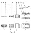
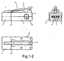
- the Figure 1-1 and 1-2 show the straight test plug according to the invention in each case in plan view and side view.
- the spring-loaded test contact (1) with a spacer sleeve (2) and the contact carrier printed circuit board (3) is shown.
- plan view of the test contact with reference numeral (11) is shown.
- the test contacts are located in a variable insulating insert (4), which is located in the changeable plug head module (5).
- the housing which has a uniform shape, consists of an upper part (6) and a lower part (7) on which there is a locking lever (8) with a spring (not shown).
- test plug (12) according to the invention is shown in side view, wherein the test plug according to the invention the plug head module (5) and the upper part (6) and the lower part (7) having a cable inlet (10) and a spring (9).
- the test plug is shown as a front view (13), wherein the test contacts (1) with the insulating insert (4) and the plug head module (5) are shown.
- the test plug according to the invention is shown by reference numeral (14) as a plan view, wherein the upper part (6) with the locking lever (8) and the plug head module (5) can be seen.
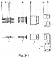
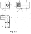
- the Figure 2-1 and 2-2 show the straight test plug according to the invention in each case in plan view and side view.
- the spring-loaded test contact (1) with a spacer sleeve (2) and the contact carrier printed circuit board (3) is shown.
- plan view becomes the test contact with reference numeral (11) shown.
- the test contacts are located in a variable insulating insert (4), which is located in the changeable plug head module (5).
- the housing which has a uniform shape, consists of an upper part (6) and a lower part (7).
- the upper part (6) and the lower part (7) have at least one cable entry (not shown).
- test plug (15) according to the invention is shown in a side view from behind, wherein the test plug according to the invention the plug head module (5) and the upper part (6) and the lower part (7) having a cable entry (10).
- the test plug is shown as a front view (16), wherein the test contacts (1) with the insulating insert (4) and the plug head module (5) and the upper part (6) and the lower part (7) are shown.
- the test plug according to the invention is shown by reference numeral (17) as a plan view, wherein the upper part (6) with the plug head (5) can be seen.
Landscapes
- Details Of Connecting Devices For Male And Female Coupling (AREA)
- Connector Housings Or Holding Contact Members (AREA)
Abstract
Prüfstecker in Modulbauweise, wobei er ein horizontal teilbares Gehäuse und ein austauschbares Aufnahmevorrichtungsmodul für ein Steckermodul oder ein Kupplungsmodul aufweist, wobei das Aufnahmevorrichtungsmodul eine gleiche äußere Form und eine veränderbare und austauschbare innere Form aufweisen, wobei die innere Form ein Steckermodul oder ein Kupplungsmodul sein kann, wobei sich an das Aufnahmevorrichtungsmodul das horizontal teilbare Gehäuse anschließt, das das Aufnahmevorrichtungsmodul aufnimmt, das zumindest einen Kabeleingang aufweist.


Description
Die Erfindung betrifft einen Prüfstecker in Modulbauweise zum elektrischen Kontaktieren, insbesondere für elektrische Anlagen und Komponenten in der Automobilindustrie.The invention relates to a test plug in modular design for electrical contacting, in particular for electrical systems and components in the automotive industry.
Ein Prüfstecker ist eine Vorrichtung zum Überprüfen von Komponenten.A test plug is a device for checking components.
Bekannte Prüfstecker, zum Beispiel in der Automobilindustrie, müssen immer wieder bei neuen Automobilkomponenten wieder komplett neu angefertigt werden, um sie an die zu prüfenden Baugruppen, wie die Zündung, die Ladeeinrichtung, die Motorsteuerung oder Motorregelung etc. eines Automobils anzupassen, was teuer und zeitaufwendig ist.Known test plugs, for example in the automotive industry, have to be completely redone again and again with new automobile components in order to adapt them to the assemblies to be tested, such as the ignition, the charging device, the engine control or engine control etc. of an automobile, which is expensive and time-consuming is.
Aufgabe der vorliegenden Erfindung ist es, den Stand der Technik zu verbessern und insbesondere einen Prüfstecker zur Verfügung zu stellen, der schnell und kostengünstig herzustellen ist und vielseitig einsetzbar ist.Object of the present invention is to improve the prior art and in particular to provide a test plug available, which is fast and inexpensive to manufacture and is versatile.
Gegenstand der vorliegenden Erfindung ist ein Prüfstecker in Modulbauweise, dadurch gekennzeichnet, dass er ein horizontal teilbares Gehäuse und ein austauschbares Aufnahmevorrichtungsmodul für ein Steckermodul oder ein Kupplungsmodul aufweist, wobei das Aufnahmevorrichtungsmodul eine gleiche äußere Form und eine veränderbare und austauschbare innere Form aufweisen, wobei die innere Form ein Steckermodul oder ein Kupplungsmodul sein kann, wobei sich an das Aufnahmevorrichtungsmodul das horizontal teilbare Gehäuse anschließt, das das Aufnahmevorrichtungsmodul aufnimmt, das zumindest einen Kabeleingang aufweist.The present invention is a test plug in modular design, characterized in that it comprises a horizontally divisible housing and an exchangeable receiving device module for a plug module or a coupling module, wherein the Aufnahmevorrichtungsmodul have a same outer shape and a variable and replaceable inner shape, wherein the inner Form may be a plug-in module or a coupling module, wherein the receiving device module, the horizontally divisible housing connects, which receives the Aufnahmevorrichtungsmodul, which has at least one cable entrance.
Aufnahmevorrichtungsmodul auf, das eine äußere Form aufweist, die in mehreren Modulgrößen verfügbar ist, zum Beispiel in 25 mm, 30 mm und 45 mm etc. Dabei muß nur die innere und äußere Form des Stecker- oder Kupplungsmodul an die jeweilige Steckverbindung angepasst werden und wird entsprechend angepasst, wobei das jeweilige Aufnahmevorrichtungsmodul immer innerhalb der jeweiligen Modulgröße das gleiche bleiben kann, unabhängig davon welches die innere und äußere Form des Stecker- oder Kupplungsmodul ist. Im Inneren befinden sich vorzugsweise bei einem Stecker oder Kupplungsmodul ein oder mehrere gefederte Kontaktstifte jeweils einzeln in einer Hülse, die sich in einer Leiterplatte befinden oder direkt in das Isolierteil eingepreßt sind, so dass sie leicht ausgetauscht werden können, ohne einen neuen Prüfstecker zu brauchen. Die Leiterplatte mit den Kontaktstiften in jeweils einer Hülse wird formschlüssig in das Aufnahmevorrichtungsmodul eingeführt. Im Gehäuse, das das Aufnahmevorrichtungsmodul aufnimmt und vorzugsweise aus zwei Teilen besteht, das in Längsrichtung geteilt werden kann, befindet sich eine Vorrichtung, die die Leiterplatte in dem Aufnahmevorrichtungsmodul gegen ein Verschieben fixiert, vorzugsweise ein Steg in jeder Gehäusehälfte. Durch die Befestigung der Hülsen in der Leiterplatte kann auch kein Verdrehen der hoch beanspruchten Hülsen auftreten.Cradle module having an outer shape, which is available in several module sizes, for example in 25 mm, 30 mm and 45 mm, etc. In this case, only the inner and outer shape of the plug or coupling module must be adapted to the respective connector and is adjusted accordingly, the respective cradle module always within the same module size can remain the same, regardless of which is the inner and outer shape of the plug or coupling module. Inside are preferably in a plug or coupling module one or more spring-loaded pins individually in a sleeve, which are located in a circuit board or pressed directly into the insulating part, so that they can be easily replaced without the need for a new test plug. The printed circuit board with the contact pins in each case a sleeve is positively inserted into the receiving device module. In the housing, which accommodates the cradle module and preferably consists of two parts which can be divided longitudinally, there is a device which fixes the circuit board in the cradle module against displacement, preferably a web in each half of the housing. By attaching the sleeves in the circuit board and no twisting of the highly stressed sleeves can occur.
Bei dem Prüfstecker, der sich aus dem Aufnahmevorrichtungsmodul und dem Gehäuse aufbaut, ist das Gehäuse zum Aufnahmevorrichtungsmodul vorzugsweise horizontal oder vertikal angeordnet. Dies ermöglicht es den Prüfstecker auch an verwinkelten Orten einzustecken, so zum Beispiel, wenn vor einer Einsteckstelle sich ein Bauteil befindet, was es nur zuläßt, dass der Prüfstecker mit einem vertikal zum Aufnahmevorrichtungsmodul aufweisenden Gehäuse eingesteckt werden kann.In the test plug, which is composed of the cradle module and the housing, the housing is preferably arranged horizontally or vertically to the cradle module. This makes it possible to insert the test plug in angled locations, such as when a component is in front of a plug, which only allows the test plug can be inserted with a housing having vertically to the receiving device module.
Unabhängig von der Anordnung des Gehäuses zum Aufnahmevorrichtungsmodul, also vertikal oder horizontal, kann der zumindest eine Kabeleingang vertikal oder horizontal zum Gehäuse angeordnet sein. Der Kabeleingang befindet sich vorzugsweise am hinteren Ende des Gehäuses des Prüfsteckers und zwar in der üblichen horizontalen Anordnung oder auch vorzugsweise vertikal zum Gehäuse an den sich gegenüberliegenden seitlichen Seiten des Gehäuses, wobei vorzugsweise die Öffnung des Kabeleingangs sich auf die beiden Gehäusehälften des horizontal teilbaren Gehäuses verteilt, so dass die Öffnung des Kabeleingangs sich aus einer Teilöffnung im unteren Teil des horizontal teilbaren Gehäuses und einer Teilöffnung im oberen Teil des horizontal teilbaren Gehäuses zusammensetzt. Zusätzlich kann der Kabeleingang neben der Möglichkeit am hinteren Ende des Gehäuses des Prüfsteckers und zwar in der üblichen horizontalen Anordnung angeordnet zu sein, auch vertikal zum Gehäuse an den beiden Gehäuseseiten, an denen das Gehäuse horizontal teilbar ist angeordnet sein, so dass das Gehäuse also ein, zwei oder drei Kabeleingänge aufweisen kann.Regardless of the arrangement of the housing for receiving device module, ie vertically or horizontally, the at least one cable entry can be arranged vertically or horizontally to the housing. The cable entrance is preferably located at the rear end of the housing of the test plug in the usual horizontal arrangement or preferably vertically to the housing at the opposite lateral sides of the housing, preferably wherein the opening of the cable entrance is distributed to the two housing halves of the horizontally divisible housing in that the opening of the cable entrance is composed of a partial opening in the lower part of the horizontally divisible housing and a partial opening in the upper part of the horizontally divisible housing. In addition, the cable entrance in addition to the possibility of being arranged at the rear end of the housing of the test plug and that in the usual horizontal arrangement, also vertically to the housing on the two sides of the housing, where the housing is horizontally divisible, so that the housing so a , two or three cable inputs can have.
Bei dem erfindungsgemäßen Prüfstecker kann das Gehäuse vorzugsweise einen Verriegelungshebel aufweisen, der an einem Ende drehbar gelagert ist und an dem anderen Ende derart ausgebildet ist, dass der Prüfstecker in seinem Gegenstück so einrastet, dass der Prüfstecker fixiert ist, vorzugsweise weist der Verriegelungshebel eine Feder hinter dem Drehpunkt des Verriegelungshebels auf, die den Hebel nach vorne zum Stecker-oder Kupplungsmodul hin drückt, so das zum Einstecken des Steckers der Verriegelungshebel heruntergedrückt wird, um nach dem Loslassen in dem Gegenstück des Steckers einzurasten. Vorzugsweise kann der Verriegelungshebel eine Justiervorrichtung aufweisen, die eine Höhenverstellung des Verriegelungshebels ermöglicht. Dies kann ein entsprechender Abstandshalter sein oder bevorzugt eine Schraube in dem Teil des Verriegelungshebels sein, der an der entsprechenden Vorrichtung des Gegensteckers einrastet, wobei durch diese Höhenverstellung bewirkt wird, dass der Verriegelungshebel zwar eingerastet bleibt, aber mit seinem hinteren Teil, mit dem er nicht einrastet und der auf der anderen Seite der Drehachse des Verriegelungshebels liegt, nicht soweit in die Höhe ragt, dass der Verriegelungshebel vorzugsweise nicht über die Ebene des Gehäuses herausragt und so beim Arbeiten mit dem Prüfstecker nicht mehr stört, da bei einem herausragenden Verriegelungshebel dieser leicht durch Anstossen mit der Hand oder einem Kabel entriegelt werden kann.In the test plug according to the invention, the housing may preferably have a locking lever which is rotatably mounted at one end and is formed at the other end such that the test plug engages in its counterpart so that the test plug is fixed, preferably, the locking lever behind a spring the pivot point of the locking lever, which pushes the lever forward to the male or coupling module, so that is depressed to insert the plug of the locking lever to lock after releasing in the counterpart of the connector. Preferably, the locking lever may have an adjusting device, which allows a height adjustment of the locking lever. This may be a corresponding spacer or, preferably, a screw in the part of the locking lever which is attached to the corresponding one Device of the mating connector engages, which is caused by this height adjustment that the locking lever remains locked, but with its rear part, with which he does not latch and which is on the other side of the axis of rotation of the locking lever, not so far protrudes into the air the locking lever preferably does not protrude beyond the plane of the housing and so no longer bothers when working with the test plug, as in an outstanding locking lever this can be easily unlocked by bumping by hand or a cable.
In einer weiteren bevorzugten Ausführungsform des erfindungsgemäßen Prüfstecker weist das Gehäuse eine Vertiefung zur Aufnahme eines Etiketts auf, wobei die Vertiefung in der das Etikett liegt, eine transparente Abdeckung aufweist. Das Etikett kann vorzugsweise aus Papier, Kunststoffolie, Schriftband oder Metall sein, auf dem vorzugsweise Informationen über den jeweiligen Prüfstecker, wie die Verwendung, die Steckerart stehen. Dieses Etikett wird durch eine transparente vorzugsweise jeder Zeit entfernbare Abdeckung aus Glas oder Kunststoff geschützt und schließt bevorzugt formschlüssig mit der Seite, in der sich die Vertiefung befindet, plan ab. Durch diese Abdeckung wird gleichzeitig das Etikett geschützt und wenn sie entfernbar ist,. können jederzeit Etiketten mit neuen Informationen eingelegt werden.In a further preferred embodiment of the test plug according to the invention, the housing has a recess for receiving a label, wherein the recess in which the label is located has a transparent cover. The label may preferably be made of paper, plastic film, tape or metal on which preferably information about the respective test plug, such as the use, the plug type stand. This label is protected by a transparent glass or plastic cover which is preferably removable at all times and preferably closes off in a form-fitting manner with the side in which the depression is located. This cover protects the label at the same time as it can be removed. Labels with new information can be inserted at any time.
In einer weiteren bevorzugten Ausführungsform weist der Kabeleingang in das Gehäuse vorzugsweise ein Gewinde auf, in das die Kabelverschraubung, die einen Mehrkant aufweist, einlegbar ist, wobei das Gehäuse eine Vorrichtung aufweist, die ein Verdrehen des Mehrkants, vorzugsweise ein üblicher handelsüblicher Sechskant, verhindert. Diese Vorrichtung, die ein Verdrehen des Mehrkant verhindert, kann vorzugsweise eine Vertiefung im Gehäuse sein, die die gleiche Form wie der Mehrkant aufweist und diesen formschlüssig aufnimmt oder bevorzugt zumindest ein Steg auf dem Gehäuse, der formschlüssig mit einer Seite des Mehrkants abschließt, so dass sich der Mehrkant nicht mehr verdrehen kann, besonders bevorzugt sind es jedoch zumindest zwei gegenüberliegende Stege, es können jedoch soviele Stege sein, wie der Mehrkant Kanten aufweist, also drei, vier, fünf, sechs bei einem Sechskant.In a further preferred embodiment, the cable entry into the housing preferably has a thread, in which the cable gland having a polygon, can be inserted, wherein the housing has a device which prevents twisting of the polygon, preferably a conventional commercial hexagon. This device, which prevents rotation of the polygon, may preferably be a recess in the housing, which has the same shape as the polygonal and this positively receives or preferably at least one web on the housing, which closes positively with one side of the polygon, so that the polygon can no longer rotate, but more preferably there are at least two opposing webs, but it can be as many webs, as the polygonal edges, So three, four, five, six at a hexagon.
Somit bietet der erfindungsgemäße Prüfstecker durch die variablen Anordnungen des Gehäuses zum Aufnahmevorrichtungsmodul und dem Kabeleingang zum Gehäuse die Möglichkeit den Prüfstecker an die unterschiedliche Geometrie der Automotiv-Prüftechnik anzupassen.Thus, the test plug according to the invention by the variable arrangements of the housing to the cradle module and the cable entrance to the housing offers the possibility to adapt the test plug to the different geometry of the automotive testing technology.
Der erfindungsgemäße Prüfstecker kann überall eingesetzt werden, wo bis jetzt schon Prüfstecker eingesetzt werden, vorzugsweise in der Automobilindustrie, Schiffsbau; Medizintechnik, Elektroindustrie etc., bevorzugt aber im Automobilbau eingesetzt werden.The test plug according to the invention can be used anywhere where test plugs are already used, preferably in the automotive industry, shipbuilding; Medical technology, electrical industry, etc., but preferably used in the automotive industry.
Der Vorteil des erfindungsgemäßen Prüfsteckers ist, dass es nun möglich ist, mit einem Gehäuse unterschiedliche Stecker und Kupplungen zu verwenden, ohne wie es bis jetzt notwendig war, immer vollständig neue Prüfstecker zu bauen. Zusätzlich ist es mit dem erfindungsgemäßen Prüfstecker möglich das Stecker- oder Kupplungsmodul, ohne das Kabel ablöten zu müssen, von z.B. einem horizontalen Gehäuse in ein vertikales Gehäuse umzubauen. Dies führt dazu, dass der erfindungsgemäßen Prüfstecker nun schneller und kostengünstiger herzustellen ist.The advantage of the test plug according to the invention is that it is now possible to use different connectors and couplings with a housing, without it being necessary until now to build completely new test plugs. In addition, with the test plug according to the invention, it is possible to have the plug or coupling module, without having to unsolder the cable, of e.g. Convert a horizontal housing into a vertical housing. This means that the test plug according to the invention is now faster and cheaper to produce.
-
Figur 1-1 und1-2 zeigen einen geraden Prüfstecker mit seinen Einzelteilen jeweils in Seitenansicht und Draufsicht.Figure 1-1 and1-2 show a straight test plug with its individual parts in each case in side view and top view.
-
Figur 2-1 und2-2 zeigen einen senkrecht zum Stecker abgewinkelten Prüfstecker mit seinen Einzelteilen jeweils in Seitenansicht und Draufsicht.Figure 2-1 and2-2 show a perpendicular to the connector angled test plug with its individual parts in each case in side view and top view.
Die
Die
Claims (11)
Applications Claiming Priority (1)
| Application Number | Priority Date | Filing Date | Title |
|---|---|---|---|
| DE200710036831 DE102007036831A1 (en) | 2007-08-03 | 2007-08-03 | Test Plugs |
Publications (2)
| Publication Number | Publication Date |
|---|---|
| EP2020705A2 true EP2020705A2 (en) | 2009-02-04 |
| EP2020705A3 EP2020705A3 (en) | 2011-09-28 |
Family
ID=39930551
Family Applications (1)
| Application Number | Title | Priority Date | Filing Date |
|---|---|---|---|
| EP08013838A Withdrawn EP2020705A3 (en) | 2007-08-03 | 2008-08-01 | Test jack connector |
Country Status (2)
| Country | Link |
|---|---|
| EP (1) | EP2020705A3 (en) |
| DE (1) | DE102007036831A1 (en) |
Families Citing this family (3)
| Publication number | Priority date | Publication date | Assignee | Title |
|---|---|---|---|---|
| DE202013001416U1 (en) | 2013-02-15 | 2014-03-17 | Gerd Thiede | Prüfsteckerschnappverschluss |
| DE102013002550B4 (en) | 2013-02-15 | 2017-09-28 | Gerd Thiede | Prüfsteckerschnappverschluss |
| DE102017003454B4 (en) | 2017-04-10 | 2020-11-12 | Stefan Thiede | Test adapter |
Family Cites Families (5)
| Publication number | Priority date | Publication date | Assignee | Title |
|---|---|---|---|---|
| US4815983A (en) * | 1987-11-13 | 1989-03-28 | International Business Machines Corporation | Customizable plugs for A.C. power cords |
| DE4001104A1 (en) * | 1990-01-17 | 1991-07-18 | Weidmueller C A Gmbh Co | Plug connector for PCB - is flexible enough to allow interchanging of connection arrangement and connected elements |
| US6227888B1 (en) * | 1994-02-24 | 2001-05-08 | Advanced Mobile Solutions, Inc. | Interchangeable plug device |
| US6544058B1 (en) * | 2001-12-31 | 2003-04-08 | Min-Chen Chang | Changeable plug base structure |
| DE202006014597U1 (en) * | 2006-09-22 | 2006-11-23 | Yang, Hsien-Lin | Plug adapter for use with sockets and connectors, has locking device integrated in adapter, and plug head with different forms, where adapter and plug head form unit after interference of hooks into locking opening and inner locking device |
-
2007
- 2007-08-03 DE DE200710036831 patent/DE102007036831A1/en not_active Withdrawn
-
2008
- 2008-08-01 EP EP08013838A patent/EP2020705A3/en not_active Withdrawn
Also Published As
| Publication number | Publication date |
|---|---|
| EP2020705A3 (en) | 2011-09-28 |
| DE102007036831A1 (en) | 2009-02-05 |
Similar Documents
| Publication | Publication Date | Title |
|---|---|---|
| EP2904982A1 (en) | Female insert for an electrosurgical device, electrosurgical device having a female insert and set with a removing tool | |
| DE102013008264A1 (en) | Connectors | |
| AT523134A1 (en) | Built-in connector | |
| DE69104310T2 (en) | ELECTRICAL CONNECTOR FOR TEST BENCH. | |
| DE202016106515U1 (en) | Connector panel for installation in a device housing | |
| EP2658039B1 (en) | Socket | |
| DE202018105109U1 (en) | Electrical connector with connection position assurance | |
| DE4311781C1 (en) | Pin or socket for jack-plug connector | |
| EP2308277B1 (en) | Housing for a connecting unit | |
| DE102007036831A1 (en) | Test Plugs | |
| DE102019115177A1 (en) | Modular PCB connector | |
| EP3066723B1 (en) | Test cable and socket adapter for a test cable | |
| DE102005016760B4 (en) | Arrangement of electrical or electronic devices | |
| EP3891849A1 (en) | Adapter housing for a contact insert for fixing on a top-hat rail | |
| DE202007010864U1 (en) | Test Plugs | |
| DE102016122397B4 (en) | Connector panel for installation in a device housing and device with a device housing with this connector panel | |
| DE102017115013B3 (en) | Contact carrier arrangement and method for mounting the contact carrier arrangement | |
| DE202018103136U1 (en) | connector part | |
| DE102021117811B3 (en) | Latching mechanism for latching a connector plug | |
| DE102010045112A1 (en) | Connector used in automobile industry of ship, has diaphragm that is inserted into aperture of clutch module within tolerance range | |
| DE19604545C2 (en) | Device for plug-in locking of collar plugs, especially circular plug-in devices | |
| DE202017104008U1 (en) | Contact carrier arrangement | |
| DE202010012505U1 (en) | Test Plugs | |
| EP1719211B1 (en) | Unplugable electrical connection | |
| DE20019792U1 (en) | Connector housing with coding device |
Legal Events
| Date | Code | Title | Description |
|---|---|---|---|
| PUAI | Public reference made under article 153(3) epc to a published international application that has entered the european phase |
Free format text: ORIGINAL CODE: 0009012 |
|
| AK | Designated contracting states |
Kind code of ref document: A2 Designated state(s): AT BE BG CH CY CZ DE DK EE ES FI FR GB GR HR HU IE IS IT LI LT LU LV MC MT NL NO PL PT RO SE SI SK TR |
|
| AX | Request for extension of the european patent |
Extension state: AL BA MK RS |
|
| PUAL | Search report despatched |
Free format text: ORIGINAL CODE: 0009013 |
|
| AK | Designated contracting states |
Kind code of ref document: A3 Designated state(s): AT BE BG CH CY CZ DE DK EE ES FI FR GB GR HR HU IE IS IT LI LT LU LV MC MT NL NO PL PT RO SE SI SK TR |
|
| AX | Request for extension of the european patent |
Extension state: AL BA MK RS |
|
| RIC1 | Information provided on ipc code assigned before grant |
Ipc: H01R 13/627 20060101ALN20110822BHEP Ipc: H01R 27/00 20060101ALI20110822BHEP Ipc: H01R 13/514 20060101ALI20110822BHEP Ipc: H01R 13/502 20060101AFI20110822BHEP |
|
| AKY | No designation fees paid | ||
| REG | Reference to a national code |
Ref country code: DE Ref legal event code: R108 Effective date: 20120606 |
|
| STAA | Information on the status of an ep patent application or granted ep patent |
Free format text: STATUS: THE APPLICATION IS DEEMED TO BE WITHDRAWN |
|
| 18D | Application deemed to be withdrawn |
Effective date: 20120329 |