EP2020705A2 - Fiche de test - Google Patents
Fiche de test Download PDFInfo
- Publication number
- EP2020705A2 EP2020705A2 EP08013838A EP08013838A EP2020705A2 EP 2020705 A2 EP2020705 A2 EP 2020705A2 EP 08013838 A EP08013838 A EP 08013838A EP 08013838 A EP08013838 A EP 08013838A EP 2020705 A2 EP2020705 A2 EP 2020705A2
- Authority
- EP
- European Patent Office
- Prior art keywords
- housing
- test plug
- module
- plug according
- test
- Prior art date
- Legal status (The legal status is an assumption and is not a legal conclusion. Google has not performed a legal analysis and makes no representation as to the accuracy of the status listed.)
- Withdrawn
Links
- 238000012360 testing method Methods 0.000 title claims abstract description 62
- 230000008878 coupling Effects 0.000 claims abstract description 12
- 238000010168 coupling process Methods 0.000 claims abstract description 12
- 238000005859 coupling reaction Methods 0.000 claims abstract description 12
- 210000004907 gland Anatomy 0.000 claims description 2
- 125000006850 spacer group Chemical group 0.000 description 3
- 238000005516 engineering process Methods 0.000 description 2
- 230000000712 assembly Effects 0.000 description 1
- 238000000429 assembly Methods 0.000 description 1
- 230000000994 depressogenic effect Effects 0.000 description 1
- 238000006073 displacement reaction Methods 0.000 description 1
- 239000011521 glass Substances 0.000 description 1
- 238000004519 manufacturing process Methods 0.000 description 1
- 230000013011 mating Effects 0.000 description 1
- 239000002184 metal Substances 0.000 description 1
- 239000004033 plastic Substances 0.000 description 1
- 239000002985 plastic film Substances 0.000 description 1
- 229920006255 plastic film Polymers 0.000 description 1
Images
Classifications
-
- H—ELECTRICITY
- H01—ELECTRIC ELEMENTS
- H01R—ELECTRICALLY-CONDUCTIVE CONNECTIONS; STRUCTURAL ASSOCIATIONS OF A PLURALITY OF MUTUALLY-INSULATED ELECTRICAL CONNECTING ELEMENTS; COUPLING DEVICES; CURRENT COLLECTORS
- H01R13/00—Details of coupling devices of the kinds covered by groups H01R12/70 or H01R24/00 - H01R33/00
- H01R13/46—Bases; Cases
- H01R13/514—Bases; Cases composed as a modular blocks or assembly, i.e. composed of co-operating parts provided with contact members or holding contact members between them
-
- H—ELECTRICITY
- H01—ELECTRIC ELEMENTS
- H01R—ELECTRICALLY-CONDUCTIVE CONNECTIONS; STRUCTURAL ASSOCIATIONS OF A PLURALITY OF MUTUALLY-INSULATED ELECTRICAL CONNECTING ELEMENTS; COUPLING DEVICES; CURRENT COLLECTORS
- H01R13/00—Details of coupling devices of the kinds covered by groups H01R12/70 or H01R24/00 - H01R33/00
- H01R13/46—Bases; Cases
- H01R13/502—Bases; Cases composed of different pieces
-
- H—ELECTRICITY
- H01—ELECTRIC ELEMENTS
- H01R—ELECTRICALLY-CONDUCTIVE CONNECTIONS; STRUCTURAL ASSOCIATIONS OF A PLURALITY OF MUTUALLY-INSULATED ELECTRICAL CONNECTING ELEMENTS; COUPLING DEVICES; CURRENT COLLECTORS
- H01R27/00—Coupling parts adapted for co-operation with two or more dissimilar counterparts
-
- H—ELECTRICITY
- H01—ELECTRIC ELEMENTS
- H01R—ELECTRICALLY-CONDUCTIVE CONNECTIONS; STRUCTURAL ASSOCIATIONS OF A PLURALITY OF MUTUALLY-INSULATED ELECTRICAL CONNECTING ELEMENTS; COUPLING DEVICES; CURRENT COLLECTORS
- H01R13/00—Details of coupling devices of the kinds covered by groups H01R12/70 or H01R24/00 - H01R33/00
- H01R13/62—Means for facilitating engagement or disengagement of coupling parts or for holding them in engagement
- H01R13/627—Snap or like fastening
- H01R13/6275—Latching arms not integral with the housing
-
- H—ELECTRICITY
- H01—ELECTRIC ELEMENTS
- H01R—ELECTRICALLY-CONDUCTIVE CONNECTIONS; STRUCTURAL ASSOCIATIONS OF A PLURALITY OF MUTUALLY-INSULATED ELECTRICAL CONNECTING ELEMENTS; COUPLING DEVICES; CURRENT COLLECTORS
- H01R13/00—Details of coupling devices of the kinds covered by groups H01R12/70 or H01R24/00 - H01R33/00
- H01R13/66—Structural association with built-in electrical component
- H01R13/665—Structural association with built-in electrical component with built-in electronic circuit
- H01R13/6658—Structural association with built-in electrical component with built-in electronic circuit on printed circuit board
Definitions
- the invention relates to a test plug in modular design for electrical contacting, in particular for electrical systems and components in the automotive industry.
- a test plug is a device for checking components.
- test plugs for example in the automotive industry, have to be completely redone again and again with new automobile components in order to adapt them to the assemblies to be tested, such as the ignition, the charging device, the engine control or engine control etc. of an automobile, which is expensive and time-consuming is.
- Object of the present invention is to improve the prior art and in particular to provide a test plug available, which is fast and inexpensive to manufacture and is versatile.
- the present invention is a test plug in modular design, characterized in that it comprises a horizontally divisible housing and an exchangeable receiving device module for a plug module or a coupling module, wherein the Radiovoriquessmodul have a same outer shape and a variable and replaceable inner shape, wherein the inner Form may be a plug-in module or a coupling module, wherein the receiving device module, the horizontally divisible housing connects, which receives the dividendvor therapiessmodul, which has at least one cable entrance.
- test plug according to the invention has a
- Cradle module having an outer shape, which is available in several module sizes, for example in 25 mm, 30 mm and 45 mm, etc.
- the respective cradle module always within the same module size can remain the same, regardless of which is the inner and outer shape of the plug or coupling module.
- Inside are preferably in a plug or coupling module one or more spring-loaded pins individually in a sleeve, which are located in a circuit board or pressed directly into the insulating part, so that they can be easily replaced without the need for a new test plug.
- the printed circuit board with the contact pins in each case a sleeve is positively inserted into the receiving device module.
- the housing which accommodates the cradle module and preferably consists of two parts which can be divided longitudinally, there is a device which fixes the circuit board in the cradle module against displacement, preferably a web in each half of the housing.
- the housing is preferably arranged horizontally or vertically to the cradle module. This makes it possible to insert the test plug in angled locations, such as when a component is in front of a plug, which only allows the test plug can be inserted with a housing having vertically to the receiving device module.
- the at least one cable entry can be arranged vertically or horizontally to the housing.
- the cable entrance is preferably located at the rear end of the housing of the test plug in the usual horizontal arrangement or preferably vertically to the housing at the opposite lateral sides of the housing, preferably wherein the opening of the cable entrance is distributed to the two housing halves of the horizontally divisible housing in that the opening of the cable entrance is composed of a partial opening in the lower part of the horizontally divisible housing and a partial opening in the upper part of the horizontally divisible housing.
- the cable entrance in addition to the possibility of being arranged at the rear end of the housing of the test plug and that in the usual horizontal arrangement, also vertically to the housing on the two sides of the housing, where the housing is horizontally divisible, so that the housing so a , two or three cable inputs can have.
- the housing may preferably have a locking lever which is rotatably mounted at one end and is formed at the other end such that the test plug engages in its counterpart so that the test plug is fixed, preferably, the locking lever behind a spring the pivot point of the locking lever, which pushes the lever forward to the male or coupling module, so that is depressed to insert the plug of the locking lever to lock after releasing in the counterpart of the connector.
- the locking lever may have an adjusting device, which allows a height adjustment of the locking lever.
- This may be a corresponding spacer or, preferably, a screw in the part of the locking lever which is attached to the corresponding one Device of the mating connector engages, which is caused by this height adjustment that the locking lever remains locked, but with its rear part, with which he does not latch and which is on the other side of the axis of rotation of the locking lever, not so far protrudes into the air the locking lever preferably does not protrude beyond the plane of the housing and so no longer bothers when working with the test plug, as in an outstanding locking lever this can be easily unlocked by bumping by hand or a cable.
- the housing has a recess for receiving a label, wherein the recess in which the label is located has a transparent cover.
- the label may preferably be made of paper, plastic film, tape or metal on which preferably information about the respective test plug, such as the use, the plug type stand.
- This label is protected by a transparent glass or plastic cover which is preferably removable at all times and preferably closes off in a form-fitting manner with the side in which the depression is located. This cover protects the label at the same time as it can be removed. Labels with new information can be inserted at any time.
- the cable entry into the housing preferably has a thread, in which the cable gland having a polygon, can be inserted, wherein the housing has a device which prevents twisting of the polygon, preferably a conventional commercial hexagon.
- This device, which prevents rotation of the polygon may preferably be a recess in the housing, which has the same shape as the polygonal and this positively receives or preferably at least one web on the housing, which closes positively with one side of the polygon, so that the polygon can no longer rotate, but more preferably there are at least two opposing webs, but it can be as many webs, as the polygonal edges, So three, four, five, six at a hexagon.
- test plug according to the invention by the variable arrangements of the housing to the cradle module and the cable entrance to the housing offers the possibility to adapt the test plug to the different geometry of the automotive testing technology.
- test plug according to the invention can be used anywhere where test plugs are already used, preferably in the automotive industry, shipbuilding; Medical technology, electrical industry, etc., but preferably used in the automotive industry.
- test plug according to the invention is that it is now possible to use different connectors and couplings with a housing, without it being necessary until now to build completely new test plugs.
- the plug or coupling module without having to unsolder the cable, of e.g. Convert a horizontal housing into a vertical housing. This means that the test plug according to the invention is now faster and cheaper to produce.
- FIGS. 1-1 and 1-2 are identical to FIGS. 1-1 and 1-2.
- FIGS. 1-1 and 1-2 are identical to FIGS. 1-1 and 1-2.
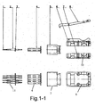
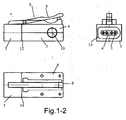
- the Figure 1-1 and 1-2 show the straight test plug according to the invention in each case in plan view and side view.
- the spring-loaded test contact (1) with a spacer sleeve (2) and the contact carrier printed circuit board (3) is shown.
- plan view of the test contact with reference numeral (11) is shown.
- the test contacts are located in a variable insulating insert (4), which is located in the changeable plug head module (5).
- the housing which has a uniform shape, consists of an upper part (6) and a lower part (7) on which there is a locking lever (8) with a spring (not shown).
- test plug (12) according to the invention is shown in side view, wherein the test plug according to the invention the plug head module (5) and the upper part (6) and the lower part (7) having a cable inlet (10) and a spring (9).
- the test plug is shown as a front view (13), wherein the test contacts (1) with the insulating insert (4) and the plug head module (5) are shown.
- the test plug according to the invention is shown by reference numeral (14) as a plan view, wherein the upper part (6) with the locking lever (8) and the plug head module (5) can be seen.
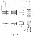
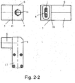
- the Figure 2-1 and 2-2 show the straight test plug according to the invention in each case in plan view and side view.
- the spring-loaded test contact (1) with a spacer sleeve (2) and the contact carrier printed circuit board (3) is shown.
- plan view becomes the test contact with reference numeral (11) shown.
- the test contacts are located in a variable insulating insert (4), which is located in the changeable plug head module (5).
- the housing which has a uniform shape, consists of an upper part (6) and a lower part (7).
- the upper part (6) and the lower part (7) have at least one cable entry (not shown).
- test plug (15) according to the invention is shown in a side view from behind, wherein the test plug according to the invention the plug head module (5) and the upper part (6) and the lower part (7) having a cable entry (10).
- the test plug is shown as a front view (16), wherein the test contacts (1) with the insulating insert (4) and the plug head module (5) and the upper part (6) and the lower part (7) are shown.
- the test plug according to the invention is shown by reference numeral (17) as a plan view, wherein the upper part (6) with the plug head (5) can be seen.
Landscapes
- Details Of Connecting Devices For Male And Female Coupling (AREA)
- Connector Housings Or Holding Contact Members (AREA)
Applications Claiming Priority (1)
| Application Number | Priority Date | Filing Date | Title |
|---|---|---|---|
| DE200710036831 DE102007036831A1 (de) | 2007-08-03 | 2007-08-03 | Prüfstecker |
Publications (2)
| Publication Number | Publication Date |
|---|---|
| EP2020705A2 true EP2020705A2 (fr) | 2009-02-04 |
| EP2020705A3 EP2020705A3 (fr) | 2011-09-28 |
Family
ID=39930551
Family Applications (1)
| Application Number | Title | Priority Date | Filing Date |
|---|---|---|---|
| EP08013838A Withdrawn EP2020705A3 (fr) | 2007-08-03 | 2008-08-01 | Fiche de test |
Country Status (2)
| Country | Link |
|---|---|
| EP (1) | EP2020705A3 (fr) |
| DE (1) | DE102007036831A1 (fr) |
Families Citing this family (3)
| Publication number | Priority date | Publication date | Assignee | Title |
|---|---|---|---|---|
| DE202013001416U1 (de) | 2013-02-15 | 2014-03-17 | Gerd Thiede | Prüfsteckerschnappverschluss |
| DE102013002550B4 (de) | 2013-02-15 | 2017-09-28 | Gerd Thiede | Prüfsteckerschnappverschluss |
| DE102017003454B4 (de) | 2017-04-10 | 2020-11-12 | Stefan Thiede | Prüfadapter |
Family Cites Families (5)
| Publication number | Priority date | Publication date | Assignee | Title |
|---|---|---|---|---|
| US4815983A (en) * | 1987-11-13 | 1989-03-28 | International Business Machines Corporation | Customizable plugs for A.C. power cords |
| DE4001104A1 (de) * | 1990-01-17 | 1991-07-18 | Weidmueller C A Gmbh Co | Steckverbindung |
| US6227888B1 (en) * | 1994-02-24 | 2001-05-08 | Advanced Mobile Solutions, Inc. | Interchangeable plug device |
| US6544058B1 (en) * | 2001-12-31 | 2003-04-08 | Min-Chen Chang | Changeable plug base structure |
| DE202006014597U1 (de) * | 2006-09-22 | 2006-11-23 | Yang, Hsien-Lin | Steckeradapter mit wechselbaren Steckerköpfen |
-
2007
- 2007-08-03 DE DE200710036831 patent/DE102007036831A1/de not_active Withdrawn
-
2008
- 2008-08-01 EP EP08013838A patent/EP2020705A3/fr not_active Withdrawn
Also Published As
| Publication number | Publication date |
|---|---|
| EP2020705A3 (fr) | 2011-09-28 |
| DE102007036831A1 (de) | 2009-02-05 |
Similar Documents
| Publication | Publication Date | Title |
|---|---|---|
| EP2904982A1 (fr) | Embout de douille pour un appareil électrochirurgical, appareil électrochirurgical doté d'un embout de douille et kit comprenant un outil de prélèvement | |
| DE102013008264A1 (de) | Steckverbinder | |
| DE202011050643U1 (de) | Steckverbindermodul | |
| AT523134A1 (de) | Einbausteckverbinder | |
| DE69104310T2 (de) | Elektrischer verbinder für prüfstand. | |
| EP2020705A2 (fr) | Fiche de test | |
| EP2658039B1 (fr) | Prise | |
| DE202018105109U1 (de) | Elektrischer Verbinder mit Anschlusspositionssicherung | |
| DE4311781C1 (de) | Stecker oder Buchse für einen Steckverbinder | |
| EP2308277B1 (fr) | Boîtier pour une unité de raccordement | |
| CH535498A (de) | Verfahren und Vorrichtung zur Codierung von Verbindungen und Anwendung des Verfahrens | |
| DE102019115177A1 (de) | Modularer Leiterkartensteckverbinder | |
| EP3066723B1 (fr) | Câble d'essai ainsi qu'adaptateur de prise pour un câble d'essai | |
| EP3891849A1 (fr) | Boîtier d'adaptateur pour un élément de contact destiné à la fixation sur un profilé chapeau | |
| DE202007010864U1 (de) | Prüfstecker | |
| DE102016122397B4 (de) | Steckverbinderpanel für den Einbau in ein Gerätegehäuse sowie Gerät mit einem Gerätegehäuse mit diesem Steckverbinderpanel | |
| DE102017115013B3 (de) | Kontaktträgeranordnung und Verfahren zur Montage der Kontaktträgeranordnung | |
| DE202018103136U1 (de) | Steckverbinderteil | |
| DE102021117811B3 (de) | Rastmechanismus zum Verrasten eines Anschlusssteckers | |
| DE102010045112A1 (de) | Prüfstecker mit Zusatz | |
| DE19604545C2 (de) | Vorrichtung zur Steckverriegelung von Kragensteckern von insbesondere Rundsteckvorrichtungen | |
| DE202017104008U1 (de) | Kontaktträgeranordnung | |
| DE202010012505U1 (de) | Prüfstecker | |
| EP1719211B1 (fr) | Connexion électrique déconnectable | |
| DE20019792U1 (de) | Steckverbinder-Gehäuse mit Kodiereinrichtung |
Legal Events
| Date | Code | Title | Description |
|---|---|---|---|
| PUAI | Public reference made under article 153(3) epc to a published international application that has entered the european phase |
Free format text: ORIGINAL CODE: 0009012 |
|
| AK | Designated contracting states |
Kind code of ref document: A2 Designated state(s): AT BE BG CH CY CZ DE DK EE ES FI FR GB GR HR HU IE IS IT LI LT LU LV MC MT NL NO PL PT RO SE SI SK TR |
|
| AX | Request for extension of the european patent |
Extension state: AL BA MK RS |
|
| PUAL | Search report despatched |
Free format text: ORIGINAL CODE: 0009013 |
|
| AK | Designated contracting states |
Kind code of ref document: A3 Designated state(s): AT BE BG CH CY CZ DE DK EE ES FI FR GB GR HR HU IE IS IT LI LT LU LV MC MT NL NO PL PT RO SE SI SK TR |
|
| AX | Request for extension of the european patent |
Extension state: AL BA MK RS |
|
| RIC1 | Information provided on ipc code assigned before grant |
Ipc: H01R 13/627 20060101ALN20110822BHEP Ipc: H01R 27/00 20060101ALI20110822BHEP Ipc: H01R 13/514 20060101ALI20110822BHEP Ipc: H01R 13/502 20060101AFI20110822BHEP |
|
| AKY | No designation fees paid | ||
| REG | Reference to a national code |
Ref country code: DE Ref legal event code: R108 Effective date: 20120606 |
|
| STAA | Information on the status of an ep patent application or granted ep patent |
Free format text: STATUS: THE APPLICATION IS DEEMED TO BE WITHDRAWN |
|
| 18D | Application deemed to be withdrawn |
Effective date: 20120329 |