EP2442438A2 - Dispositif de pompe pour un appareil ménager, appareil ménager et procédé de fonctionnement d'un dispositif d'entraînement - Google Patents
Dispositif de pompe pour un appareil ménager, appareil ménager et procédé de fonctionnement d'un dispositif d'entraînement Download PDFInfo
- Publication number
- EP2442438A2 EP2442438A2 EP11183903A EP11183903A EP2442438A2 EP 2442438 A2 EP2442438 A2 EP 2442438A2 EP 11183903 A EP11183903 A EP 11183903A EP 11183903 A EP11183903 A EP 11183903A EP 2442438 A2 EP2442438 A2 EP 2442438A2
- Authority
- EP
- European Patent Office
- Prior art keywords
- drive motor
- current
- circuit arrangement
- phase
- pump device
- Prior art date
- Legal status (The legal status is an assumption and is not a legal conclusion. Google has not performed a legal analysis and makes no representation as to the accuracy of the status listed.)
- Withdrawn
Links
Images

Classifications
-
- H—ELECTRICITY
- H02—GENERATION; CONVERSION OR DISTRIBUTION OF ELECTRIC POWER
- H02P—CONTROL OR REGULATION OF ELECTRIC MOTORS, ELECTRIC GENERATORS OR DYNAMO-ELECTRIC CONVERTERS; CONTROLLING TRANSFORMERS, REACTORS OR CHOKE COILS
- H02P6/00—Arrangements for controlling synchronous motors or other dynamo-electric motors using electronic commutation dependent on the rotor position; Electronic commutators therefor
- H02P6/20—Arrangements for starting
- H02P6/21—Open loop start
-
- H—ELECTRICITY
- H02—GENERATION; CONVERSION OR DISTRIBUTION OF ELECTRIC POWER
- H02P—CONTROL OR REGULATION OF ELECTRIC MOTORS, ELECTRIC GENERATORS OR DYNAMO-ELECTRIC CONVERTERS; CONTROLLING TRANSFORMERS, REACTORS OR CHOKE COILS
- H02P6/00—Arrangements for controlling synchronous motors or other dynamo-electric motors using electronic commutation dependent on the rotor position; Electronic commutators therefor
- H02P6/20—Arrangements for starting
- H02P6/22—Arrangements for starting in a selected direction of rotation
Definitions
- the invention relates to a pump device for a household appliance.
- the pump device comprises a drive motor for driving an impeller, wherein the rotor of the drive motor has permanent magnets and the stator of the drive motor has at least three phase phases.
- the pump device also comprises a circuit arrangement for operating the drive motor.
- the invention also relates to a domestic appliance with such a pump device.
- the invention further relates to a method for operating a drive motor, by which a pump wheel of a domestic appliance is driven.
- the pump device known from this document comprises a housing which forms a one-piece pump chamber.
- This pump chamber accommodates in its interior a rotor of a drive motor and a pump wheel.
- the rotor carries permanent magnets, which are fluid-tightly formed with a sheath made of plastic material.
- Outside the housing is the stator of the drive motor.
- This stator comprises nine windings which are connected in such a way that a total of three phase strands are formed.
- the phase strings are energized by an inverter.
- Pumping devices for home appliances are also from the pamphlets DE 103 52 487 A1 such as DE 10 2005 036 818 A1 known.
- the pump device comprises a circuit arrangement for operating the drive motor.
- the stator of the drive motor has at least three phase strings, and the circuit arrangement comprises an electrical control element for controlling a current flow through the associated phase string for each phase string.
- the circuit arrangement is designed to control the rotational speed and / or the direction of rotation of the drive motor by actuating the control elements.
- the effect according to the invention is achieved in that the rotational speed and / or the direction of rotation of the drive motor can be controlled by the circuit arrangement.
- the control of the rotational speed and / or the direction of rotation of a pump wheel takes place in a domestic appliance.
- such a rotational speed of the impeller can be adjusted according to need, in which the noise is reduced to a minimum or the pump power, that is, the amount of the conveyed water per unit time, is set to a predetermined value.
- the water flow rate can be adapted to a sewage system.
- the change in the direction of rotation of the impeller allows, for example, that selbiges impeller free of foreign bodies or lint and thus can work properly. As a result, a frequent maintenance of the pump device with the associated time and cost is unnecessary.
- the drive motor is a permanent-magnet synchronous motor (also known as "brushless DC machine").
- the speed can be varied without much effort by appropriate control of the controls, namely by changing the frequency of the voltage applied to the phase strands electrical voltages.
- a frequency converter - ie one by a control unit controllable inverter - the frequency of the voltage and thereby the speed of the impeller can be controlled.
- the direction of rotation of the impeller can be controlled by appropriate control of such a frequency converter.
- the frequency converter can supply any voltage and amplitude of any voltage
- the pumping equipment can be supplied with any mains voltage, whether 220 V mains with 50 Hz frequency or 120 V mains with 60 Hz frequency , operate. Regardless of the amplitude and the frequency of the mains voltage, the desired speed and the direction of rotation of the drive motor can be adjusted.
- the pump device can thus be used with different network variants, without having to rebuilt and adapted to a specific network variant.
- Another advantage of the pump device is that an existing pump - for example, from the document DE 103 42 050 A1 - Does not require any significant change in order to operate at different speeds and / or in different directions of rotation.
- the stator, in particular its windings, and the circuit arrangement can be redesigned in order to ensure the control of the rotational speed and / or the direction of rotation.
- the term domestic appliance is understood to mean, in particular, a water-conducting household appliance.
- the household appliance may be a washing machine, a tumble dryer, a washer-dryer or even a dishwasher.
- the stator has an even number of phase strands.
- the stator has four windings and also four phase strands. Then the drive motor can be brought into the preselected direction without much effort, for example in a unipolar stepping motor operation.
- the drive motor can be brought into the preselected direction without much effort, for example in a unipolar stepping motor operation.
- By using four phase strings it is also possible to switch off two phase phases in a synchronous operation of the drive motor, and the phase strings can be cooled in pairs.
- the circuit arrangement can each generate a pulse-like course of the current in the phase strands and thereby cause a stepwise movement of the rotor. Then, the drive motor is driven according to the stepping motor operation. In Such a stepper motor operation, the angular position of the rotor is always known, and the rotor can be put into operation in a predetermined direction without much effort.
- the stepper motor operation is preferably a unipolar stepper motor operation.
- the stepwise movement of the rotor is preferably up to a predetermined speed, and upon reaching this speed, the drive motor is converted into a synchronous operation.
- synchronous operation the position of the rotor changes uniformly, and the rotor moves synchronously with the rotating field generated by the stator.
- the transition from stepping motor operation to synchronous operation takes place, for example, at a speed between 100 and 150 revolutions per minute.
- the circuit arrangement switches off at least one control element in the synchronous mode of the drive motor and controls only predetermined control elements. Then only those phase strands of the stator are energized, which are coupled to the driven controls. In the case of a stator with four phase phases, this can be done, for example, in such a way that only two phase phases of the stator are energized in the synchronous mode.
- This has the advantage that when a predetermined critical temperature of the energized phase strands is reached-for example due to a high current intensity-these phase strands are decoupled from an operating voltage and the previously unused phase strands can be energized. So the energizing of the phase strands of the drive motor can take place alternately in synchronous operation. The non-energized phase strands can thus be cooled, and it can be achieved overall a longer operating life of the pump device.
- the circuit arrangement can detect the currents flowing through the phase strands of the stator.
- the controls are coupled to a common current sense resistor.
- the circuit may detect a current flowing through the current detection resistor. From the stream information about the respective current operating state of the drive motor and the pump device can be obtained. For example, information about the temperature as well as about the torque of the drive motor can be obtained from the current. The speed and / or the direction of rotation of the drive motor can then be controlled depending on this information.
- By capturing the Stromes comes from the pump device without an additional thermal protection (for example, a so-called I 2 t protection).
- the current intensity of the current can be evaluated by a control unit, and when a predetermined current intensity is exceeded, the drive motor can be switched off or the phase strands of the stator can be decoupled from an operating voltage.
- the controls be it transistors or other electrical switches, protected from thermal overloads.
- control terminals of the controls may each be coupled to an output of a comparator.
- a DC voltage having a threshold may be applied to a first input of the comparator, and a second input of the comparator may be coupled to the current sensing resistor.
- a voltage dropping across the current detection resistor is thus applied to the second input. If the amplitude of the voltage dropping across the current detection resistor is below the threshold value, then the comparator outputs a logical "one", ie a predetermined DC voltage, and the control element coupled to the output of the comparator is triggered.
- the comparator If the voltage dropping across the current detection resistor exceeds the threshold value, that is, the current intensity of the current flowing across the current sensing resistor exceeds a predetermined value, the comparator outputs a logic "zero". In this case, the control terminal of the control is coupled to a reference potential, and the control is not driven. By doing so, such current spikes that occur for a relatively short time can be limited. When current spikes occur for a longer period of time, the controls are preferably turned off by a control unit.
- the detection of the current flowing through the phase strands of the stator makes it possible to draw conclusions about a torque or a load of the drive motor.
- the torque or the load is determined as a function of the current intensity of the detected current and / or as a function of a phase difference between the phase of the detected current and the phase of a voltage applied to the phase strands.
- the relationship is that the higher the torque, the higher the current of the detected current and the larger the phase difference. So is the information about the torque of the drive motor for controlling the same to disposal. It can be deduced depending on the torque on the operating state of the pump impeller or on the prevailing in the pump wheel operating conditions, for example, a liqueur state of the water to be pumped or on the amount of water.
- the control of the drive motor can thus be carried out depending on its torque, namely it can be set depending on the operating conditions in the pump wheel in each case an optimal speed and / or direction of rotation.
- Too high a torque or too high a current intensity of the current usually mean that there is a high degree of contamination or linting of the impeller. If the impeller is rotated in such a case in the other direction, it frees itself from the lint, and it is unnecessary maintenance of the pump device with the associated time and possibly the cost.
- the drive motor can be controlled depending on the operating state of the impeller.
- the information about the operating conditions in the area of the impeller can be obtained by means of the detected current.
- the rotational speed of the drive motor is regulated as a function of the detected current, namely in particular as a function of the current intensity of this current and / or as a function of the phase difference between the phase of the current and the phase of the current induced voltage.
- the speed and thus the amount of water to be delivered per unit time can be regulated depending on the torque of the drive motor.
- Such a control can be carried out in particular in a spin operation of a washing machine.
- An inventive household appliance comprises a pump device according to the invention or a preferred embodiment thereof.
- the home appliance may be a washing machine, a tumble dryer, a washer-dryer or a dishwasher.
- a pump wheel of a domestic appliance is driven by the drive motor.
- the stator has at least three phase strands.
- the speed and / or the direction of rotation of the drive motor is / are controlled by means of a circuit arrangement.
- Fig. 1 is a schematic representation of a cross section of a drive motor 1 of a pump device, which is installed in a domestic appliance, for example in a washing machine.
- the pump device may therefore be a drain pump of the washing machine.
- the pump device serves to convey water.
- the drive motor 1 is a permanent-magnet synchronous motor whose rotor 2 permanent magnets N, S has.
- the rotor 2 has a total of two poles N, S.
- a stator 3 of the drive motor 1 has four teeth 4a to 4d, which are directed onto the rotor 2 and face the rotor 2.
- a winding 5a to 5d is wound around each tooth 4a to 4d.
- the windings 5a to 5d can be energized separately from each other, so that a total of four phase strands of the drive motor 1 are formed.
- the first winding 5a is electrically connected via a first line 6 with its opposite second winding 5b.
- This first line 6 is coupled to a first supply terminal 7, to which a direct electrical voltage can be applied.
- the first winding 5a is coupled to a first terminal 8, which can be coupled to a reference potential via a control element, for example via a transistor.
- the second winding 5b is also coupled to a second terminal 9, which can be coupled via a control to a reference potential. If an electrical voltage with respect to the reference potential is present at the first supply connection 7, then the first and the second winding 5a, 5b can be energized by being coupled to the reference potential.
- the third winding 5c is electrically coupled via a second line 10 to the fourth winding 5d opposite it.
- the second line 10 is connected to a second supply terminal 11, to which a DC electrical voltage can be applied.
- the third winding 5c is further provided with a third one Connection 12 which can be coupled via a control element, for example a transistor, to a reference potential.
- the fourth winding 5d is also connected to a fourth terminal 13 and can be coupled via a control to a reference potential. If an electrical voltage is present at the second supply connection 11, the third and the fourth winding 5c, 5d can be energized by being coupled to the reference potential.
- Fig. 2 shows a pumping device 14, the in Fig. 1 illustrated drive motor 1 and a circuit 15 includes.
- the first and second supply terminals 7, 11 are connected to a common DC link 16, to which a rectified electrical Voltage of about 310 V DC is applied, namely with respect to a reference potential 17.
- This DC voltage is determined using a in Fig. 2 not shown circuit including a rectifier and a DC link capacitor provided, namely from an AC supply voltage from a supply network.
- the terminals 8, 9, 12, 13 of the windings 5a to 5d are coupled to an inverter 18 having four control elements 19a to 19d, here four insulated gate bipolar transistors (IGBT) or four MOSFETs ,
- the first terminal 8 is connected to the drain or collector terminal of the first control element 19a
- the second terminal 9 is connected to the drain or collector terminal of the second control element 19b
- the third terminal 12 is connected to the drain or collector
- the collector terminal of the third control element 19c is connected
- the fourth terminal 13 is connected to the drain or collector terminal of the fourth control element 19d.
- the source or investigator terminals of the control elements 19a to 19d are coupled to the reference potential 17 via a common pole 20 and via a current detection resistor (shunt) 21.
- the gate terminals of the control elements 19a to 19d are connected to a driver circuit 22.
- the driver circuit 22 includes four comparators 24a to 24d.
- the gate terminal of the first control element 19a is connected via a first ohmic resistor 23a
- the gate terminal of the second control element 19b is connected via a second ohmic resistor 23b to an output of the second comparator 24b
- the gate terminal of the third control element 19c is connected via a third ohmic resistor 23c to an output of the third comparator 24c
- the gate terminal of the fourth control element 19d is connected through a fourth ohmic resistor 23d to an output of the fourth comparator 24d.
- the positive inputs of the comparators 24a to 24d are coupled to a control unit 25, in particular a microprocessor. At the respective positive inputs of the comparators 24a to 24d, electrical voltages are applied whose amplitudes each correspond to a threshold value.
- the negative inputs of the comparators 24 a to 24 d are connected to the pole 20 and thus also to the current detection resistor 21. At the negative inputs of the comparators 24a to 24d there is thus a voltage drop across the current detection resistor 21.
- the comparators 24a to 24d are also supplied with a DC voltage of for example 15 V DC by the control unit 25 and are coupled to the reference potential 17 beyond. If the voltage dropping across the current detection resistor 21 exceeds the threshold value applied to the positive input of one of the comparators 24a to 24d, then this comparator 24a to 24d outputs a logical "zero". In this case, the gate terminal of the control element 19a to 19d coupled to this comparator 24a to 24d is coupled to the reference potential 17, and the control element 19a to 19d is non-conductive.
- the pole 20 and the current detection resistor 21 are also connected to an input of the control unit 25.
- the control unit 25 can thus detect and evaluate the voltage dropping across the current detection resistor 21.
- the control unit 25 can infer depending on this voltage to the current flowing through the current detection resistor 21 current.
- the control unit 25 can thus detect and evaluate the currents flowing through the windings 5a to 5d of the drive motor 1.
- the drive motor 1 drives an impeller, which promotes water.
- the pump device 14 is for example a drain pump.
- the control unit 25 first receives control commands, for example from one central control device of the washing machine. These control commands may include a desired pumping capacity, with which the pump device 14 is to convey the water, that is, the amount of water delivered per unit time. These control commands may also include the direction of rotation of the impeller. So the desired speed and the direction of rotation in the control unit 25 are given. The control unit 25 then controls the inverter 18 and thus the drive motor 1 at.
- the control unit 25 When the drive motor 1 is put into operation, the control unit 25 effects pulsed control of the control elements 19a to 19d and thus pulse-like courses of the currents flowing through the windings 5a to 5d.
- the drive motor 1 is thus controlled according to the unipolar stepper motor operation. Such a stepping motor operation makes it possible to start the drive motor 1 in the desired direction of rotation without much effort.
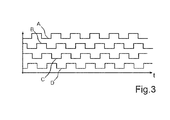
- Fig. 3 shows exemplary courses of the currents in the windings 5a to 5d in the stepping motor operation of the drive motor 1.
- the time t is plotted on the x-axis.
- the first curve A shows the current profile in the first winding 5a of the drive motor 1
- the second curve B the current waveform in the second winding 5b
- the third curve C the current waveform in the third winding 5c
- the fourth curve D the current waveform in the fourth Winding 5d.
- the current waveforms of the windings 5a to 5d are each phase-shifted by 90 °. That is, the current in the second winding 5b has a phase shift with respect to the current in the first winding 5a of 90 °.
- the current in the third winding 5c has a phase shift of 90 ° with respect to the current in the second winding 5b
- the current in the fourth winding 5d has a phase shift of 90 ° with respect to the current in the third winding 5c.
- Such an operation of the drive motor 1 is referred to as unipolar stepping motor operation, since the windings 5a to 5d are energized with current only in one direction.
- the drive motor 1 is operated up to a predetermined speed, for example, up to about 150 rpm. At this speed, a transition to a synchronous operation takes place. In this synchronous operation, only two windings 5a to 5d can be energized, namely in pairs the first and the second winding 5a, 5b or the third and the fourth winding 5c, 5d. This allows cooling of the non-energized windings 5a to 5d in the synchronous operation, so that a longer operating time at a high speed of the drive motor 1 can be achieved.
- control unit 25 detects the current flowing through the current detection resistor 21. From the amperage of this induced current or also from a phase difference between the phase of this current and the phase of a voltage applied to the windings 5a to 5d, the control unit 25 can calculate the instantaneous torque of the drive motor 1. This torque is then a measure of the instantaneous load of the drive motor 1. The drive of the drive motor 1 is carried out by the control unit 25 depending on the calculated torque.
- the control unit 25 turns off the drive motor 1. Such a procedure avoids that the impeller generates noise.
- the control unit 25 changes the direction of rotation of the drive motor 1, and the pump wheel can free itself from the lint. There is first a deceleration of the drive motor 1 and then a re-acceleration of the same in the other direction in the stepping motor operation.
- a pump device 14 whose functionality is increased compared to the prior art. Namely, the rotational speed and the direction of rotation of the impeller can be freely adjusted, for example, in dependence on the torque of the drive motor 1.
- the change in the speed allows, for example, the setting of the pump power, that is the amount of water to be pumped per unit time.
- the adjustment of the speed also reduces the noise of the pump device 14 over the prior art.
- the maintenance of the pump device 14 must be made less frequently than in the prior art, namely, the impeller can in fact rid itself of impurities or fluff, this by changing the direction of rotation.
- Such a pump device 14 also allows a completely new design of the impeller, this can namely be designed for both directions of rotation and, for example, be equipped with movable wings.
Landscapes
- Engineering & Computer Science (AREA)
- Power Engineering (AREA)
- Control Of Motors That Do Not Use Commutators (AREA)
- Control Of Non-Positive-Displacement Pumps (AREA)
- Structures Of Non-Positive Displacement Pumps (AREA)
Applications Claiming Priority (1)
| Application Number | Priority Date | Filing Date | Title |
|---|---|---|---|
| DE102010042491A DE102010042491A1 (de) | 2010-10-15 | 2010-10-15 | Pumpeneinrichtung für ein Hausgerät, Hausgerät und Verfahren zum Betreiben eines Antriebsmotors |
Publications (1)
| Publication Number | Publication Date |
|---|---|
| EP2442438A2 true EP2442438A2 (fr) | 2012-04-18 |
Family
ID=44719708
Family Applications (1)
| Application Number | Title | Priority Date | Filing Date |
|---|---|---|---|
| EP11183903A Withdrawn EP2442438A2 (fr) | 2010-10-15 | 2011-10-05 | Dispositif de pompe pour un appareil ménager, appareil ménager et procédé de fonctionnement d'un dispositif d'entraînement |
Country Status (2)
| Country | Link |
|---|---|
| EP (1) | EP2442438A2 (fr) |
| DE (1) | DE102010042491A1 (fr) |
Cited By (3)
| Publication number | Priority date | Publication date | Assignee | Title |
|---|---|---|---|---|
| CN104779853A (zh) * | 2015-03-19 | 2015-07-15 | 四川长虹电器股份有限公司 | 室外风机启动控制方法 |
| EP3424398A1 (fr) * | 2017-07-06 | 2019-01-09 | BSH Hausgeräte GmbH | Procédé de fonctionnement d'un appareil électroménager à circulation d'eau à détermination de la durée de marche à vide d'une pompe améliorée et appareil électroménager correspondant |
| WO2023186852A1 (fr) * | 2022-03-31 | 2023-10-05 | Vitesco Technologies GmbH | Procédé de fonctionnement d'un dispositif de transport de fluide, dispositif de transport de fluide, programme d'ordinateur et support lisible par ordinateur |
Families Citing this family (2)
| Publication number | Priority date | Publication date | Assignee | Title |
|---|---|---|---|---|
| DE102013113576A1 (de) | 2013-12-05 | 2015-06-11 | Prominent Gmbh | Sensorlose Störungserkennung bei Dosierpumpen mit Schrittmotor |
| DE102016216737B4 (de) | 2016-09-05 | 2018-03-15 | BSH Hausgeräte GmbH | Wäschepflegegerät mit einer Steuerung |
Citations (3)
| Publication number | Priority date | Publication date | Assignee | Title |
|---|---|---|---|---|
| DE10352487A1 (de) | 2003-07-22 | 2005-02-10 | BSH Bosch und Siemens Hausgeräte GmbH | Pumpe mit integriertem Motor |
| DE10342050A1 (de) | 2003-09-11 | 2005-04-07 | BSH Bosch und Siemens Hausgeräte GmbH | Elektrische Maschine und diese verwendende Pumpe |
| DE102005036818A1 (de) | 2005-08-04 | 2007-02-08 | BSH Bosch und Siemens Hausgeräte GmbH | Pumpengehäuse, Pumpe und wasserführendes Haushaltsgerät |
Family Cites Families (4)
| Publication number | Priority date | Publication date | Assignee | Title |
|---|---|---|---|---|
| US4928051A (en) * | 1987-05-05 | 1990-05-22 | Jozsef Demeter | Electric motor |
| US5329214A (en) * | 1992-08-28 | 1994-07-12 | Compaq Computer Corporation | Motor drive circuit |
| DE10207232B4 (de) * | 2002-02-21 | 2005-11-17 | Diehl Ako Stiftung & Co. Kg | Schaltungsanordnung zur Ansteuerung eines elektromotorischen Antriebs, insbesondere Pumpenantriebs, in einem Haushaltgroßgerät |
| JP3953358B2 (ja) * | 2002-04-18 | 2007-08-08 | 東洋電機製造株式会社 | 永久磁石電動機の制御方法 |
-
2010
- 2010-10-15 DE DE102010042491A patent/DE102010042491A1/de not_active Withdrawn
-
2011
- 2011-10-05 EP EP11183903A patent/EP2442438A2/fr not_active Withdrawn
Patent Citations (3)
| Publication number | Priority date | Publication date | Assignee | Title |
|---|---|---|---|---|
| DE10352487A1 (de) | 2003-07-22 | 2005-02-10 | BSH Bosch und Siemens Hausgeräte GmbH | Pumpe mit integriertem Motor |
| DE10342050A1 (de) | 2003-09-11 | 2005-04-07 | BSH Bosch und Siemens Hausgeräte GmbH | Elektrische Maschine und diese verwendende Pumpe |
| DE102005036818A1 (de) | 2005-08-04 | 2007-02-08 | BSH Bosch und Siemens Hausgeräte GmbH | Pumpengehäuse, Pumpe und wasserführendes Haushaltsgerät |
Cited By (6)
| Publication number | Priority date | Publication date | Assignee | Title |
|---|---|---|---|---|
| CN104779853A (zh) * | 2015-03-19 | 2015-07-15 | 四川长虹电器股份有限公司 | 室外风机启动控制方法 |
| CN104779853B (zh) * | 2015-03-19 | 2017-12-08 | 四川长虹电器股份有限公司 | 室外风机启动控制方法 |
| EP3424398A1 (fr) * | 2017-07-06 | 2019-01-09 | BSH Hausgeräte GmbH | Procédé de fonctionnement d'un appareil électroménager à circulation d'eau à détermination de la durée de marche à vide d'une pompe améliorée et appareil électroménager correspondant |
| CN109208266A (zh) * | 2017-07-06 | 2019-01-15 | Bsh家用电器有限公司 | 用于通过更好地确定泵的空转负载来运行加水式家用器具的方法和家用器具 |
| CN109208266B (zh) * | 2017-07-06 | 2022-03-29 | Bsh家用电器有限公司 | 用于通过更好地确定泵的空转负载来运行加水式家用器具的方法和家用器具 |
| WO2023186852A1 (fr) * | 2022-03-31 | 2023-10-05 | Vitesco Technologies GmbH | Procédé de fonctionnement d'un dispositif de transport de fluide, dispositif de transport de fluide, programme d'ordinateur et support lisible par ordinateur |
Also Published As
| Publication number | Publication date |
|---|---|
| DE102010042491A1 (de) | 2012-05-03 |
Similar Documents
| Publication | Publication Date | Title |
|---|---|---|
| EP2025054B1 (fr) | Procede de fonctionnement d'un moteur a commutation electronique et moteur pour mettre en oeuvre ledit procede | |
| DE19846831B4 (de) | Verfahren und Vorrichtung zur Ermittlung der Rotorstellung von Synchronmotoren | |
| DE102007040560A1 (de) | Verfahren zur Ansteuerung eines Umrichters sowie zugehörige Vorrichtung | |
| DE102007030072A1 (de) | Elektrischen Antriebseinrichtung für ein Wasserführendes Haushaltsgerät | |
| DE20302543U1 (de) | Schaltungsanordnung zur Ansteuerung eines elektromotorischen Antriebs, insbesondere Pumpenantriebs, in einem Haushaltsgroßgerät | |
| DE102010042491A1 (de) | Pumpeneinrichtung für ein Hausgerät, Hausgerät und Verfahren zum Betreiben eines Antriebsmotors | |
| DE102014107949A1 (de) | Verfahren und Vorrichtung zur Erkennung eines Nulldurchgangs eines Stroms durch einen Strang eines bürstenlosen Gleichstrom- motors | |
| EP2627814B1 (fr) | Procédé pour commander un processus de freinage d'un moteur d'entraînement de lave-linge, dispositif d'entraînement et lave-linge associés | |
| WO2019149502A1 (fr) | Procédé de fonctionnement d'un moteur à champ tournant d'un véhicule à moteur, dispositif de transmission, unité d'entraînement ainsi que véhicule à moteur | |
| DE10332228B4 (de) | Steuerungsverfahren für einen bürstenlosen Elektromotor, insbesonde Lüftermotor | |
| EP2899879A2 (fr) | Procédé de fonctionnement et dispositif de commande d'une machine à rotation électrique sans brosse | |
| DE102009028810A1 (de) | Verfahren zum Ermitteln einer Unwucht bei einer Wäschetrommel einer Waschmaschine im Schleuderbetrieb, Antriebsvorrichtung und Waschmaschine mit einer Antriebsvorrichtung | |
| DE102013014480A1 (de) | Verfahren zum Betreiben eines Elektromotors | |
| EP2628240B1 (fr) | Dispositif d'entraînement servant à entraîner un élément d'appareil ménager, appareil ménager et procédé pour faire fonctionner un appareil ménager | |
| DE102015220910A1 (de) | Spannungsüberwachung für eine Motoransteuerschaltung eines bürstenlosen Waschmaschinenmotors | |
| DE202016104176U1 (de) | Integrierte Schaltung, Treiberschaltung für einen Motor, Motoranordnung und Geräteausrüstung damit | |
| EP2020721B1 (fr) | Dispositif de commutation destiné à la surveillance d'un tachymètre pour un moteur d'entraînement d'un tambour d'un lave-linge | |
| DE112007001763B4 (de) | Schaltungsanordnung | |
| LU103364B1 (de) | Antriebssystem | |
| DE102008007403A1 (de) | Permanentmagneterregte elektrische Maschine für ein Hausgerät | |
| DE102007024354A1 (de) | Verfahren zum Betrieb eines elektronisch kommutierten Motors, und Motor zur Durchführung eines solchen Verfahrens | |
| EP3301807B1 (fr) | Entraînement synchronisé à deux brins | |
| EP2319976B1 (fr) | Appareil ménager destiné à l'entretien de pièces de linge et procédé de fonctionnement d'un moteur à courant continu à brosses | |
| EP4593281A1 (fr) | Système d'entraînement | |
| WO2019042936A1 (fr) | Commande d'un moteur de ventilateur pour un comportement cem amélioré |
Legal Events
| Date | Code | Title | Description |
|---|---|---|---|
| PUAI | Public reference made under article 153(3) epc to a published international application that has entered the european phase |
Free format text: ORIGINAL CODE: 0009012 |
|
| AK | Designated contracting states |
Kind code of ref document: A2 Designated state(s): AL AT BE BG CH CY CZ DE DK EE ES FI FR GB GR HR HU IE IS IT LI LT LU LV MC MK MT NL NO PL PT RO RS SE SI SK SM TR |
|
| AX | Request for extension of the european patent |
Extension state: BA ME |
|
| RAP1 | Party data changed (applicant data changed or rights of an application transferred) |
Owner name: BSH HAUSGERAETE GMBH |
|
| STAA | Information on the status of an ep patent application or granted ep patent |
Free format text: STATUS: THE APPLICATION IS DEEMED TO BE WITHDRAWN |
|
| 18D | Application deemed to be withdrawn |
Effective date: 20170503 |