EP2020736A2 - Bürstenloser Motor - Google Patents
Bürstenloser Motor Download PDFInfo
- Publication number
- EP2020736A2 EP2020736A2 EP08013018A EP08013018A EP2020736A2 EP 2020736 A2 EP2020736 A2 EP 2020736A2 EP 08013018 A EP08013018 A EP 08013018A EP 08013018 A EP08013018 A EP 08013018A EP 2020736 A2 EP2020736 A2 EP 2020736A2
- Authority
- EP
- European Patent Office
- Prior art keywords
- phase
- unit
- motor
- brushless motor
- coils
- Prior art date
- Legal status (The legal status is an assumption and is not a legal conclusion. Google has not performed a legal analysis and makes no representation as to the accuracy of the status listed.)
- Withdrawn
Links
- 230000005291 magnetic effect Effects 0.000 claims description 29
- 230000008859 change Effects 0.000 claims description 6
- 230000001172 regenerating effect Effects 0.000 claims description 4
- 239000011347 resin Substances 0.000 claims description 3
- 229920005989 resin Polymers 0.000 claims description 3
- 230000005284 excitation Effects 0.000 description 53
- 230000008929 regeneration Effects 0.000 description 14
- 238000011069 regeneration method Methods 0.000 description 14
- 238000010586 diagram Methods 0.000 description 11
- 238000006243 chemical reaction Methods 0.000 description 9
- 230000004048 modification Effects 0.000 description 7
- 238000012986 modification Methods 0.000 description 7
- 238000000034 method Methods 0.000 description 5
- 230000004044 response Effects 0.000 description 4
- 230000008901 benefit Effects 0.000 description 3
- 230000005540 biological transmission Effects 0.000 description 3
- 230000007423 decrease Effects 0.000 description 3
- 230000001747 exhibiting effect Effects 0.000 description 3
- 238000007493 shaping process Methods 0.000 description 3
- 238000013461 design Methods 0.000 description 2
- 238000006073 displacement reaction Methods 0.000 description 2
- 230000017525 heat dissipation Effects 0.000 description 2
- 238000012423 maintenance Methods 0.000 description 2
- 230000007246 mechanism Effects 0.000 description 2
- 238000007789 sealing Methods 0.000 description 2
- 239000000725 suspension Substances 0.000 description 2
- 230000005355 Hall effect Effects 0.000 description 1
- 238000010276 construction Methods 0.000 description 1
- 238000005260 corrosion Methods 0.000 description 1
- 230000007797 corrosion Effects 0.000 description 1
- 230000003247 decreasing effect Effects 0.000 description 1
- 239000000428 dust Substances 0.000 description 1
- 230000000694 effects Effects 0.000 description 1
- 238000005516 engineering process Methods 0.000 description 1
- 230000005279 excitation period Effects 0.000 description 1
- 230000005294 ferromagnetic effect Effects 0.000 description 1
- 230000006870 function Effects 0.000 description 1
- 230000006872 improvement Effects 0.000 description 1
- 230000005415 magnetization Effects 0.000 description 1
- 230000007659 motor function Effects 0.000 description 1
- 230000000149 penetrating effect Effects 0.000 description 1
- 230000001144 postural effect Effects 0.000 description 1
- 238000012546 transfer Methods 0.000 description 1
- 238000005406 washing Methods 0.000 description 1
Images








Classifications
-
- H—ELECTRICITY
- H02—GENERATION; CONVERSION OR DISTRIBUTION OF ELECTRIC POWER
- H02K—DYNAMO-ELECTRIC MACHINES
- H02K21/00—Synchronous motors having permanent magnets; Synchronous generators having permanent magnets
- H02K21/12—Synchronous motors having permanent magnets; Synchronous generators having permanent magnets with stationary armatures and rotating magnets
- H02K21/24—Synchronous motors having permanent magnets; Synchronous generators having permanent magnets with stationary armatures and rotating magnets with magnets axially facing the armatures, e.g. hub-type cycle dynamos
-
- H—ELECTRICITY
- H02—GENERATION; CONVERSION OR DISTRIBUTION OF ELECTRIC POWER
- H02K—DYNAMO-ELECTRIC MACHINES
- H02K11/00—Structural association of dynamo-electric machines with electric components or with devices for shielding, monitoring or protection
- H02K11/20—Structural association of dynamo-electric machines with electric components or with devices for shielding, monitoring or protection for measuring, monitoring, testing, protecting or switching
- H02K11/21—Devices for sensing speed or position, or actuated thereby
- H02K11/215—Magnetic effect devices, e.g. Hall-effect or magneto-resistive elements
-
- H—ELECTRICITY
- H02—GENERATION; CONVERSION OR DISTRIBUTION OF ELECTRIC POWER
- H02K—DYNAMO-ELECTRIC MACHINES
- H02K7/00—Arrangements for handling mechanical energy structurally associated with dynamo-electric machines, e.g. structural association with mechanical driving motors or auxiliary dynamo-electric machines
- H02K7/14—Structural association with mechanical loads, e.g. with hand-held machine tools or fans
-
- B—PERFORMING OPERATIONS; TRANSPORTING
- B60—VEHICLES IN GENERAL
- B60K—ARRANGEMENT OR MOUNTING OF PROPULSION UNITS OR OF TRANSMISSIONS IN VEHICLES; ARRANGEMENT OR MOUNTING OF PLURAL DIVERSE PRIME-MOVERS IN VEHICLES; AUXILIARY DRIVES FOR VEHICLES; INSTRUMENTATION OR DASHBOARDS FOR VEHICLES; ARRANGEMENTS IN CONNECTION WITH COOLING, AIR INTAKE, GAS EXHAUST OR FUEL SUPPLY OF PROPULSION UNITS IN VEHICLES
- B60K7/00—Disposition of motor in, or adjacent to, traction wheel
- B60K7/0007—Disposition of motor in, or adjacent to, traction wheel the motor being electric
Definitions
- the present invention relates to a brushless motor that utilizes permanent magnets and electromagnetic coils.
- the brushless motor disclosed in JP 2001-298982A is one known examples of a brushless motor that utilizes permanent magnets and electromagnetic coils.
- a rotor rotates within a stator, and the rotational motion of the rotor is conveyed to a rotation axis connected to the rotor.
- the rotational motion of the rotation axis is conveyed to a driven member such as a wheel with a transmission mechanism such as gears, or with a direct drive mechanism.
- a driven member such as a wheel with a transmission mechanism such as gears, or with a direct drive mechanism.
- An object of the present invention is to provide technology that is able to rotate the driven member without rotating the central axis of the motor.
- a brushless motor comprising: a stator having a electromagnetic coil and a position sensor; an axis fixed to the stator; and a rotor having a permanent magnet, the rotor rotating around the axis; wherein the rotor is linked to a driven member that is driven by the brushless motor.
- the axis is fixed to the stator, the rotor rotates around the axis, and the driven member is linked to the rotor, so it is possible to rotate the driven member without rotating the axis of the motor.
- the present invention may be realized reduced in various forms such as a brushless motor or a brushless generator; a method for control (or driving method) of these; an actuator using these, an electrical generating device, or a movable body; and so on.
- Figs. 1A-1D are cross section diagrams showing the configuration of the motor main unit of the brushless motor as a first embodiment of this invention.
- This motor main unit has an axis unit 64, a stator unit 10, and a rotor unit 30.
- the stator unit 10 and the rotor unit 30 have a roughly round-disk shape.
- the axis unit 64 is attached to a suspension 1 of a movable body such as a vehicle or the like by an axis fixing unit 64a, and the axis unit64 is fixed so that the axis unit 64 itself does not rotate.
- the rotor unit 30 has an upper rotor unit 30U and a lower rotor unit 30L.
- Fig. 1B is a horizontal cross section diagram of the upper rotor unit 30U.
- the upper rotor unit 30U has an upper rotational casing unit 31U, a bearing unit 65U, and four permanent magnets 32U each having generally fan-shaped contours.
- the rotor unit 30 can rotate around the axis unit 64 with the aid of the bearing unit 65U.
- the bearing unit 65U may be realized by a ball bearing, for example.
- the lower rotor unit 30L is identical in design to the upper rotor unit 30U and has been omitted from the illustration.
- the direction of magnetization of the magnets 32U, 32L is parallel to the axis unit 64.
- the axis-end-part fixing member 64e is attached to the end part of the axis unit 64 ( Fig. 1A ), such that the bearing unit 65U does not come off due to rotation of the motor.
- a wheel unit 70 is fixed on the upper rotational casing unit 31U by a fixing screw 50.
- a sealing cap 70c is attached to the center part of the wheel unit 70.
- the sealing cap 70c prevents foreign matter from getting into the inside of the motor.
- a wheel part 71 which acts as the wheel of the movable body, is attached on the outer periphery of the wheel unit 70.
- Fig. 1C is a horizontal sectional view of the stator unit 10.
- the stator unit 10 has a plurality of phase A coils 12A, a plurality of phase B coils 12B, and a support member 14 supporting these coils 12A, 12B.
- Fig. 1C depicts the phase A coils 12A.
- the phase B coils 12B have this same design.
- a drive circuit unit 500 is installed in the stator unit 10 as well. As shown in Fig.
- the center part of the axis unit 64 has a hollow structure, which provides a passage for a drive power wire 278 for supplying power to each coil 12 and a control wire 279 for sending signals to the drive circuit unit 500. Also, in order to collect regenerated power from each coil 12 (this will be described later), it is preferable to pass a receiving power wire 280 (hereafter also called the "power source wiring 280") through the hollow part. This saves space for the wiring.
- the rotor unit 30 rotates around the axis unit 64, the rotor unit 30 spins the wheel, and the axis unit 64 is fixed and does not rotate ( Fig. 1A ). Therefore, twisting force is not applied to the axis unit 64. Because of this, it is possible to reduce the torsional strength of the axis unit 64, thereby making the motor lighter. Since there is no torsion on the axis unit 64, it is not necessary to use a transmission means such as gears. This results in no transmission loss, stable control and high-speed response. This is especially effective for postural control which requires fast response of forward rotation and reverse rotation.
- the wheel unit 70 and the wheel part 71 can easily be attached to the rotor unit 30 and be detached from the rotor unit 30 by using the fixing screw unit 50, so it is possible to do maintenance of the wheel unit 70 and the wheel part 71 separated from the motor main unit. Also note that it is possible to transfer the heat generated within the rotor unit 30 to outside of the motor using the upper rotational casing unit 31U as a heat dissipation structure. Therefore, the motor of this embodiment has the advantage of high heat dissipation.
- Fig. 1A when the stator unit 10 is completely covered with the upper and lower rotational casing units 31U and 31L, it is possible to easily realize a sealed structure that is resistant to dirt and the like from the outside.
- the sealed structure will make it possible to use this motor as the wheel of an amphibious vehicle.
- the sealed structure also prevents dust or the like from penetrating inside of the motor, so it is possible to realize a maintenance-free fan motor.
- the wheel unit 70 and the wheel part 71 correlate to the "driven member" of this invention.
- Fig. 1D is a conceptual diagram depicting the relationship of the stator unit 10 and the upper and lower rotor units 30U, 30L. However, the rotational casing unit 31 and the bearing unit 65 of the rotor unit 30 are omitted from this diagram.
- On the support member 14 of the stator unit 10 are provided a magnetic sensor 40A for phase A use and a magnetic sensor 40B for phase B use.
- the magnetic sensors 40A, 40B are used to detect the position of the rotor units 30U, 30L (i.e. the phase of the motor). These sensors will hereinafter be referred to as the "phase A sensor” and the "phase B sensor.”
- the phase A sensor 40A is positioned at a center location between two of the phase A coils 12A.
- phase B sensor 40B is positioned at a center location between two of the phase B coils 12B.
- the phase B sensor 40B is positioned together with the phase A coils 12A at the upper face of the support member 14, but it could instead be positioned at the lower face of the support member 14. This applies to the phase A sensor 40A as well.
- the phase B sensor 40B is positioned inside one of the phase A coils 12A, which has the advantage of ensuring space for placement of the sensor 40B.
- the magnets 32U, 32L are each positioned at a constant magnetic pole pitch Pm, with adjacent magnets being magnetized in opposite directions.
- the phase A coils 12A are arranged at constant pitch Pc, with adjacent coils being excited in opposite directions. This applies to the phase B coils 12B as well.
- the magnetic pole pitch Pm is equal to the coil pitch Pc, and in terms of electrical angle is equivalent to ⁇ .
- An electrical angle of 2 ⁇ is associated with the mechanical angle or distance of displacement when the phase of the drive signal changes by 2 ⁇ .
- the rotor units 30U, 30D undergo displacement by the equivalent of twice the magnetic pole pitch Pm.
- the phase A coils 12A and the phase B coils 12B are positioned at locations phase-shifted by ⁇ /2 from each other.
- the magnets 32U of the upper rotor unit 30U and the magnets 32L of the lower rotor unit 30L are positioned with their magnetic poles which face towards the stator unit 10 having mutually different polarity (N pole and S pole).
- the magnets 32U of the upper rotor unit 30U and the magnets 32L of the lower rotor unit 30L are positioned with their opposite poles facing one another.
- the magnetic field between these magnets 32U, 32L will be represented by substantially straight magnetic field lines and will be closed between these magnets 32U, 32L. It will be appreciated that this closed magnetic field is stronger than the open magnetic field.
- magnetic yokes 34U, 34L made of a ferromagnetic body will be disposed respectively on the outside faces of the magnets 32U, 32L.
- the magnetic yokes 34U, 34L make it possible to further strengthen the magnetic field in the coils.
- the magnetic yokes 34U, 34L may be omitted.
- the magnetic sensors 40A and 40B, and the drive circuit unit 500 it is preferable to cover any or all of these with resin. By doing this, it is possible to suppress the corrosion of these. Also, if the resin covering the coils 12A, 12B is in contact with the axis unit 64, the heat generated from the coils 12A and 12B is conveyed to the axis unit 64, and it becomes possible to cool the coils 12A, 12B by using the axis unit 64 as the heat sink.
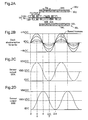
- Figs. 2A-2D illustrate the relationship of sensor output and back electromotive force waveform.
- Fig. 2A is identical to Fig. 1D .
- Fig. 2B shows an exemplary waveform of back electromotive force generated by the phase A coils 12A.
- Figs. 2C and 2D show exemplary waveforms of sensor outputs SSA, SSB of the phase A sensor 40A and the phase B sensor 40B.
- These sensors 40A, 40B can generate sensor outputs SSA, SSB of shape substantially similar to the back electromotive force of the coils during motor operation.
- the back electromotive force of the coils 12A shown in Fig. 2B tends to rise together with motor speed but its waveform shape (sine wave) maintains substantially similar shape.
- Hall ICs that utilize the Hall effect, for example, could be employed as the sensors 40A, 40B.
- the sensor output SSA and the back electromotive force Ec are each a sine wave or waveform approximating a sine wave.
- the drive control circuit of this motor utilizing the sensor outputs SSA, SSB, applies voltage of shape substantially similar to the back electromotive force Ec to the respective coils 12A, 12B.
- An electric motor functions as an energy conversion device that converts between mechanical energy and electrical energy.
- the back electromagnetic force of the coils represents mechanical energy of the electric motor converted to electrical energy. Consequently, where electrical energy applied to the coils is converted to mechanical energy (that is, where the motor is driven), it is possible to drive the motor with maximum efficiency by applying voltage of similar waveform to the back electromagnetic force.
- voltage of similar waveform to the back electromagnetic force means voltage that generates current flowing in the opposite direction from the back electromagnetic force.
- Fig. 3A is a model diagram illustrating the relationship of applied voltage and electromotive force of a coil.
- the coil is simulated in terms of AC back electromotive force Ec and resistance Rc.
- a voltmeter V is parallel-connected to the AC application voltage Ei and the coil.
- the back electromotive force Ec is also termed “induced voltage Ec” and the application voltage Ei is also termed “exciting voltage Ei.”
- the polarity of the back electromotive force Ec measured with the switch SW open will be the same as the polarity of the application voltage Ei measured with the switch SW closed.
- application of voltage of substantially similar waveform to the back electromagnetic force herein refers to application of voltage having the same polarity as, and waveform of substantially similar shape to, the back electromotive force Ec measured by the voltmeter V.
- Fig. 3B illustrates an overview of the driving method employed in the present embodiment.
- the motor is simulated by the phase A coils 12A, the permanent magnets 32U, and the phase A sensor 40A.
- AC voltage Es also termed "sensor voltage Es”
- This sensor voltage Es has a waveform shape substantially similar to that of the induced voltage Ec of the coil 12A.
- PWM signal which simulates the sensor voltage Es for on/off control of the switch SW it will be possible to apply to the coils 12A exciting voltage Ei of substantially similar waveform to the induced voltage Ec.
- the advantages of driving a motor through application of voltage of similar waveform to the back electromotive force are improved motor efficiency and reduced vibration and noise.
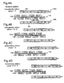
- Figs. 4A-4D are illustrations depicting forward rotation operation of the brushless motor of the embodiment.
- Fig. 4A depicts the state just before the phase reaches 0.
- the letters "N" and "S” shown at locations of the phase A coils 12A and the phase B coils 12B indicate the excitation direction of these coils 12A, 12B.
- the rotor units 30U, 30L turn in the forward rotation direction (rightward in the drawing).
- the excitation direction of the phase A coils 12A reverses (see Figs. 2A-2D ).
- FIG. 4B depicts a state where the phase has advanced to just before ⁇ /2. At the timing of the phase going to ⁇ /2, the excitation direction of the phase B coils 12B reverses.
- Fig. 4C depicts a state where the phase has advanced to just before ⁇ . At the timing of the phase going to ⁇ , the excitation direction of the phase A coils 12B again reverses.
- Fig. 4D depicts a state where the phase has advanced to just before 3 ⁇ /2. At the timing of the phase going to 3 ⁇ /2, the excitation direction of the phase B coils 12B again reverses.
- the phase A sensor 40A is positioned such that the location at which the polarity of its sensor output switches will be situated at a location where the center of a phase A coil 12A faces the center of a permanent magnet 32U.
- the phase B sensor 40B is positioned such that the location at which the polarity of the sensor output switches will be situated at a location where the center of a phase B coil 12A faces the center of a permanent magnet 32L.
- Fig. 5A-5D are illustrations depicting reverse rotation operation of the brushless motor of the embodiment.
- Fig. 5A-5D respectively depicts states where the phase has reached just before 0, ⁇ /2, ⁇ , and 3/ ⁇ 2.
- Reverse rotation operation can be accomplished, for example, by reversing the polarity of the drive voltages of the coils 12A, 12B to from that of the respective drive voltages during forward rotation operation.
- Fig. 6 is a block diagram depicting an internal configuration of a drive circuit unit in the present embodiment.
- the drive circuit unit 500 has a CPU 110, a drive controller 100, a regeneration controller 200, a driver circuit 150, a rectifier circuit 250, and a power supply unit 300.
- the two controllers 100, 200 are connected to the CPU 110 via a bus 102.
- the drive controller 100 and the driver circuit 150 are circuits for carrying out control in instances where driving force is to be generated in the electric motor.
- the regeneration controller 200 and the rectifier circuit 250 are circuits for carrying out control in instances where power from the electric motor is to be regenerated.
- the regeneration controller 200 and the rectifier circuit 250 will be referred to collectively as a "regeneration circuit.”
- the drive controller 100 will also be referred to as a "drive signal generating circuit.”
- the power supply unit 300 is a circuit for supplying various power supply voltages to other circuits in the drive circuit unit 500. In Fig. 6 , for convenience, only the power lines going from the power supply unit 300 to the drive controller 100 and the driver circuit 150 are shown; power lines leading to other circuits have been omitted.
- Fig. 7 shows a configuration of a phase A driver circuit 120A and a phase B driver circuit 120B included in the driver circuit 150 ( Fig. 6 ).
- the phase A driver circuit 120A is an H bridge circuit for delivering AC drive signals DRVA1, DRVA2 to the phase A coils 12A.
- the white circles next to terminal portions of blocks which indicate drive signals denote negative logic and indicate that the signal is inverted.
- the arrows labeled IA1, IA2 respectively indicate the direction of current flow with the A1 drive signal DRVA1 and the A2 drive signal DRVA2.
- the configuration of the phase B driver circuit 120B is the same as the configuration of the phase A driver circuit 120A.
- Figs. 8A-8E illustrate internal configuration and operation of the drive controller 100 ( Fig. 6 ).
- the drive controller 100 has a basic clock generating circuit 510, a 1/N frequency divider 520, a PWM unit 530, a moving direction register 540, a multiplier 550, an encoder unit 560, an AD converter 570, a voltage control value register 580, and an excitation interval setting unit 590.
- the drive controller 100 generates both phase A drive signals and phase B drive signal, and the basic clock generating circuit 510, the divider 520, and the moving direction register 540 are used in common by both the phase-A and phase-B.
- Fig. 8A only depicts circuitry for phase A, for convenience of illustration.
- phase B The same circuitry for phase B is also included in the drive controller 100.
- the other constitutional elements that exist respectively for the phase-A and phase-B are depicted only as the phase-A circuit constitution in Fig. 8A for convenience of illustration. But the same constitutional elements as those for the phase A are also provided in the drive controller 100 for the phase B.
- the basic clock generating circuit 510 generates a clock signal PCL of prescribed frequency, and includes a PLL circuit for example.
- the frequency divider 520 generates a clock signal SDC having a frequency equal to 1/N the frequency of the clock signal PCL.
- the value of N is set to a prescribed constant. This value of N has been previously established in the frequency divider 520 by the CPU 110.
- the PWM unit 530 generates the AC single-phase drive signals DRVA1, DRVA2 ( Fig.
- a value RI indicating the direction for motor rotation is established in the moving direction register 540, by the CPU 110.
- the motor will rotate forward when the forward/reverse direction value RI is L level, and rotate in reverse rotation when H level.
- the other signals Ma, Pa, Ea supplied to the PWM unit 530 are determined as follows.
- the output SSA of the magnetic sensor 40 is supplied to the AD converter 570.
- the AD converter 570 performs AD conversion of this sensor output SSA to generate a digital value of sensor output.
- the output of the AD converter 570 has a range, for example, of FFh to 0h (the "h" suffix denotes hexadecimal), with the median value of 80h corresponding to the middle point of the sensor waveform.
- the encoder unit 560 converts the range of the sensor output value subsequent to the AD conversion, and sets the value of the middle point of the sensor output value to 0.
- the sensor output value Xa generated by the encoder unit 560 assumes a prescribed range on the positive side (e.g. between +127 and 0) and a prescribed range on the negative side (e.g. between 0 and -127).
- the value supplied to the multiplier 560 by the encoder unit 560 is the absolute value of the sensor output value Xa; the positive/negative sign thereof is supplied to the PWM unit 530 as the positive/negative sign signal Pa.
- the voltage control value register 580 stores a voltage control value Ya established by the CPU 110.
- This voltage control value Ya together with the excitation interval signal Ea discussed later, functions as a value for setting the application voltage to the motor.
- the multiplier 550 performs multiplication of the voltage control value Ya and the sensor output value Xa output from the encoder unit 560 and conversion to an integer; the multiplication value Ma thereof is supplied to the PWM unit 530.
- Figs. 8B-8E depict operation of the PWM unit 530 in instances where the multiplication value Ma takes various different values. Here, it is assumed that there are no non-excitation intervals, so that all intervals are excitation intervals.
- the PWM unit 530 is a circuit that, during one period of the clock signal SDC, generates one pulse with a duty factor of Ma/N. Specifically, as shown in Figs. 8B-8E , the pulse duty factor of the single-phase drive signals DRVA1, DRVA2 increases in association with increase of the multiplication value Ma.
- the first drive signal DRVA1 is a signal that generates a pulse only when the sensor output SSA is positive and the second drive signal DRVA2 is a signal that generates a pulse only when the sensor output SSA is negative; in Figs. 8B-8E , both are shown together.
- the second drive signal DRVA2 is shown in the form of pulses on the negative side.
- Figs. 9A-9C depict correspondence between sensor output waveform and waveform of the drive signals generated by the PWM unit 530.
- “Hiz” denotes a state of high impedance where the magnetic coils are not excited.
- the single-phase drive signals DRVA1, DRVA2 are generated by PWM control using the analog waveform of the sensor output SSA. Consequently, using these single-phase drive signals DRVA1, DRVA2 it is possible to supply to the coils effective voltage that exhibits changes in level corresponding to change in the sensor outputs SSA.
- the PWM unit 530 is constructed such that drive signals are output only during the excitation intervals indicated by the excitation interval signal Ea supplied by the excitation interval setting unit 590, with no drive signals being output at intervals except for the excitation intervals (non-excitation intervals).
- Fig. 9C depicts drive signal waveforms produced in the case where excitation intervals EP and non-excitation intervals NEP have been established by the excitation interval signal Ea. During the excitation intervals EP, the drive signal pulses of Fig. 9B are generated as is; during the non-excitation intervals NEP, no pulses are generated.
- excitation intervals EP and non-excitation intervals NEP in this way, voltage will not be applied to the coils in proximity to the middle point of the back electromotive force waveform (i.e. in proximity to the middle point of the sensor output), thus making possible further improvement of motor efficiency.
- the excitation intervals EP will be established at intervals symmetric about the peak point of the back electromotive force waveform; and preferably the non-excitation intervals NEP will be established in intervals symmetric about the middle point (center) of the back electromotive force waveform.
- the voltage control value Ya is set to a value less than 1, the multiplication value Ma will be decreased in proportion to the voltage control value Ya. Consequently, effective adjustment of application voltage is possible by the voltage control value Ya as well.
- Fig. 10 is a block diagram depicting the internal configuration of the PWM unit 530 ( Fig. 8A ).
- the PWM unit 530 has a counter 531, an EXOR circuit 533, and a drive waveform shaping circuit 535. Their operation will be described below.
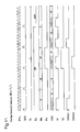
- Fig. 11 is a timing chart depicting operation of the PWM unit 530 during forward rotation of the motor.
- the drawing show the two clock signals PCL and SDC, the forward/reverse direction value RI, the excitation interval signal Ea, the multiplication value Ma, the positive/negative sign signal Pa, the counter value CM1 in the counter 531, the output SI of the counter 531, the output S2 of the EXOR circuit 533, and the output signals DRVA1, DRVA2 of the drive waveform shaping circuit 535.
- the counter 531 repeats an operation of decrementing the count value CM1 to 0, in sync with the clock signal PCL.
- the initial value of the count value CM1 is set to the multiplication value Ma.
- negative multiplication values Ma are shown as well; however, the counter 531 uses the absolute values
- the output S1 of the counter 531 is set to H level when the count value CM1 is not 0, and drops to L level when the count value CM1 is 0.
- the EXOR circuit 533 outputs a signal S2 that represents the exclusive OR of the positive/negative sign signal Pa and the forward/reverse direction value RI. Where the motor is rotating forward, the forward/reverse direction value RI will be at L level. Consequently, the output S2 of the EXOR circuit 533 will be a signal identical to the positive/negative sign signal Pa.
- the drive waveform shaping circuit 535 generates the drive signals DRVA1, DRVA2 from the output S1 of the counter 531 and the output S2 of the EXOR circuit 533.
- the signal during intervals in which the output S2 of the EXOR circuit 533 is at L level will be output as the drive signal DRVA1
- the signal during intervals in which the output S2 of the EXOR circuit 533 is at H level will be output as the drive signal DRVA2.
- the excitation interval signal Ea falls to L level thereby establishing a non-excitation interval NEP. Consequently, neither of the drive signals DRVA1, DRVA2 will be output during this non-excitation interval NEP, and a state of high impedance will be maintained.
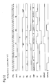
- Fig. 12 is a timing chart depicting operation of the PWM unit 530 during reverse rotation of the motor. Where the motor is rotating in reverse, the forward/reverse direction value RI will be at H level. As a result, the two drive signals DRVA1, DRVA2 switch relative to Fig. 11 , and it will be appreciated that the motor runs in reverse as a result.
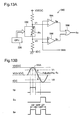
- Figs. 13A and 13B illustrate the internal configuration and operation of an excitation interval setting unit 590.
- the excitation interval setting unit 590 has an electronic variable resistor 592, a voltage comparators 594, 596, and an OR circuit 598.
- the resistance Rv of the electronic variable resistor 592 is set by the CPU 110.
- the voltages V1, V2 at either terminal of the electronic variable resistor 592 are supplied to one of the input terminals of the voltage comparators 594, 596.
- the sensor output SSA is supplied to the other input terminal of the voltage comparators 594, 596.
- the output signals Sp, Sn of the voltage comparators 594, 596 are input to the OR circuit 598.
- the output of the OR circuit 598 is the excitation interval signal Ea, which is used to differentiate excitation intervals and non-excitation intervals.
- Fig. 13B depicts operation of the excitation interval setting unit 590.
- the output Sp of the first voltage comparator 594 goes to H level
- the output Sn of the second voltage comparator 596 goes to H level.
- the excitation interval signal Ea is a signal derived by taking the logical sum of the these output signals Sp, Sn. Consequently, as shown at bottom in Fig.
- the excitation interval signal Ea can be used as a signal indicating excitation intervals EP and non-excitation intervals NEP.
- the excitation intervals EP and non-excitation intervals NEP are established by the CPU 110, by adjusting the variable resistance Rv.
- Figs. 14A and 14B are illustrations comparing various signal waveforms in the case where the motor of the embodiment discussed above is driven by a rectangular wave, and where driven by a sine wave (for descriptive purposes, the waveform of the back electromotive force is also called a sine wave).
- Fig. 15 depicts another configuration example of the phase A driver circuit 120A and the phase B driver circuit 120B included in the driver circuit 150 ( Fig. 6 ).
- These driver circuits 120A, 120B are furnished with amplifier circuits 122 situated in front of the gate electrodes of the transistors which make up the driver circuits 120A, 120B shown in Fig. 7 . While the type of transistor also differs from that in Fig. 7 , transistors of any type can be used as the transistors. In order to be able to drive the motor of the present invention over a wider operating range with regard to torque and speed, it will be preferable to establish variable power supply voltage VDD of the driver circuits 120A, 120B.
- the level of the drive signals DRVA1, DRVA2, DRVB1, DRVB2 applied to the gate voltages of the transistors will change proportionally therewith. By so doing the motor can be driven using a wider power supply voltage VDD range.
- the amplifier circuits 122 are circuits for changing the level of the drive signals DRVA1, DRVA2, DRVB1, DRVB2.
- the power supply unit 300 of the drive circuit unit 500 shown in Fig. 6 will supply variable power supply voltage VDD to the driver circuit 150.
- Fig. 16 shows the speed of the motor of the embodiment in the absence of load. As will be apparent from the graph, in the absence of load the motor of the embodiment will rotate at stable speed down to very low speed. The reason is that since there is no magnetic core, cogging does not occur.
- Fig. 17 illustrates the internal configuration of the regeneration controller 200 and rectifier circuit 250 shown in Fig. 6 .
- the regeneration controller 200 comprises an phase A charge switching unit 202 and a phase B charge switching unit 204, both connected to the bus 102, and an electronically variable resistor 206.
- the output signals of the two charge switching units 202, 204 are applied to the input terminals of the two AND circuits 211, 212.
- the phase A charge switching unit 202 outputs a signal of a "1" level when the regenerative power from the phase A coils 12A is recovered, and outputs a signal of a "0" level when the power is not recovered.
- the switching of those signal levels is conducted with the CPU 110.
- the presence or absence of regeneration from the phase A coils 12A and the presence or absence of regeneration from the phase B coil 12B can be set independently. Therefore, for example, electric power can be regenerated from the phase B coils 12B, while generating a drive force in the motor by using the phase A coils 12A.
- the drive controller 100 shown in Fig. 6 similarly, may have a configuration such that whether or not the drive force is generated by using the phase A coils 12A and whether or not the drive force is generated by using the phase B coils 12B can be set independently.
- the motor can be operated in an operation mode such that a drive force is generated in any one of the two sets of coils 12A, 12B, while electric power is regenerated in the other coils.
- the voltage across the electronically variable resistor 206 is applied to one of the two input terminals of the four voltage comparators 221-224.
- the phase A sensor signal SSA and phase B sensor signal SSB are applied to the other input terminal of the voltage comparators 221-224.
- the output signals TPA, BTA, TPB, BTB of the four voltage comparators 221-224 can be called "mask signals” or "permission signals”.
- the mask signals TPA, BTA for the phase A coils are inputted into the OR circuit 231, and the mask signals TPB, BTB for the phase B are inputted into the other OR circuit 232.
- the outputs of those OR circuits 231, 232 are supplied to the input terminals of the above-mentioned two AND circuits 211, 212.
- the output signals MSKA, MSKB of those AND circuits 211, 212 are called "mask signals" or "permission signals".
- the configurations of the four voltage comparators 221-224 and the two OR circuits 231, 232 are identical to two sets of the voltage comparators 594, 596, and the OR circuit 598 of the excitation interval setting unit 590 shown in Fig. 13A . Therefore, the output signal of the OR circuit 231 for the phase A coils is similar to the excitation interval signal Ea shown in Fig. 13B . Further, when the output signal of the phase A charge switching unit 202 is at a "1" level, the mask signal MSKA outputted from the AND circuit 211 for the phase A coils is identical to the output signal of the OR circuit 231. Those operations are identical to those relating to the phase B.
- the rectifier circuit 250 has the circuitry for the phase A coils which includes a full-wave rectifier circuit 252 comprising a plurality of diodes, two gate transistors 261, 262, a buffer circuit 271, and an inverter circuit 272 (NOT circuit).
- the identical circuitry is also provided for the phase B.
- the gate transistors 261, 262 are connected to the power wiring 280 for regeneration. It is preferable to use Schottky diodes which have excellent characteristics of low Vf as the plurality of diodes.
- the AC power generated in the phase A coils 12A is rectified with the full-wave rectifier circuit 252.
- the mask signal MSKA for the phase A coils and the inverted signal thereof are supplied to the gates of the gate transistors 261, 262, and the gate transistors 261, 262 are ON/OFF controlled accordingly. Therefore, within a period in which at least one of the mask signals TPA, BTA outputted from the voltage comparators 221, 222 is at an H level, the regenerated power is outputted to the power source wiring 280. On the other hand, within an interval in which both mask signals TPA, BTA are at an L level, power regeneration is inhibited.
- the regenerated power can be recovered by using the regeneration controller 200 and rectifier circuit 250. Furthermore, the regeneration controller 200 and rectifier circuit 250 can restrict the interval in which the regenerated power from the phase A coils 12A and phase B coils 12B is recovered, according to the mask signal MSKA for the phase A coils and the mask signal MSKB for the phase B coils, thereby making it possible to adjust the quantity of the regenerated power.
- the axis unit 64 is fixed to the stator unit 10, and the rotor unit 30 rotates around the axis unit 64.
- the driven member such as the wheel part 71 is linked to the rotor unit 30, so it is possible to rotate the driven member without rotating the central axis of the motor.
- Fig. 18A and 18B are explanatory drawings showing another example of the motor configuration of the first embodiment 1.
- the wheel part 71 is attached to the outer periphery of the motor, but instead of that, it is also possible to attach a gear 71b and to use the motor main unit as part of the gear ( Fig. 18A ). Instead of the gear 71b, it is also possible to attach a pulley 71c ( Fig. 18B ).
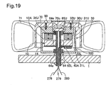
- Fig. 19 is an explanatory drawing showing the motor configuration of the embodiment 2.
- the difference from the embodiment 1 shown in Figs. 1A-1D is only that the permanent magnet 32 and the coil 12 are provided on only one side of the support member 14, and the remainder of the configuration is the same as the embodiment 1. In this way, as a one side excitation motor as well, it is possible to rotate the driven member without rotating the central axis of the motor.
- Fig. 20A and 20B are explanatory drawings showing the configuration of the motor of the embodiment 3.
- the difference from the embodiment 1 shown in Figs. 1A-1D is only that the permanent magnet 32 is arranged at the outer periphery side of the coil 12, and the remainder of the configuration is the same as the embodiment 1( Fig. 20A ).
- the wheel part 71 it is also possible to attach a blade 71d, and to use this motor as a fan motor ( Fig. 20B ). In this way, even if the arrangement of the permanent magnet 32 and the coil 12 is the same arrangement as that of an outer rotor type motor, it is possible to rotate the driven member without rotating the central axis of the motor.
- an analog magnetic sensor is employed in the preceding embodiments, it is possible to use digital magnetic sensors having multivalue analog-like output in place of analog magnetic sensors. Both an analog magnetic sensor and a digital magnetic sensor having multivalue analog-like output will have an output signal exhibiting analog variation.
- an "output signal exhibiting analog variation” refers in the broad sense to include both analog output signals, and multilevel digital output signals having three or more levels, excluding On/Off binary output.
- the PWM circuit various circuit configurations besides that shown in Fig. 10 .
- the drive signal may be generated by some method besides PWM control.
- a circuit that generates drive signals by some method besides PWM control.
- a circuit that amplifies sensor output to generate an analog drive signal may be used.
- the AD converter 570 may be replaced with a voltage comparator.
- the drive waveform will be rectangular rather than a sine wave drive waveform, and thus noise/vibration will occur; on the other hand, it will be possible to realize the drive control circuit by means of an inexpensive IC.
- the present invention is also applicable to motors that do not include regenerating circuits and to generators that do not include drive control circuits.
- the present invention is applicable to the motors for various types of devices such as automated camera platforms for projectors, automated camera platforms for video cameras, electric vehicles, blimps, helicopters, jet engines (pressure portion), robots, fan motors, clocks (clock hand drive), drum type washing machines (single rotation), jet coasters, vibration motors, toys, and the like.
- Fig. 21 is an explanatory drawing showing a railway vehicle using a motor according to the embodiment of this invention.
- This railway vehicle 1000 has a motor 1010 and a wheel 1020.
- This motor 1010 drives the wheel 1020.
- the motor 1010 is used as a generator when the railway vehicle 1000 is applied the brake, and regenerates power.
- this motor 1010 it is possible to use the various types of brushless motor described above.
- a fixing screw unit 50 for attachment and detachment was provided, but it is also possible to eliminate the fixing screw unit 50 and form the wheel unit 70 and the rotor unit 30 as a single unit.
Landscapes
- Engineering & Computer Science (AREA)
- Power Engineering (AREA)
- Microelectronics & Electronic Packaging (AREA)
- Control Of Motors That Do Not Use Commutators (AREA)
- Brushless Motors (AREA)
Applications Claiming Priority (2)
| Application Number | Priority Date | Filing Date | Title |
|---|---|---|---|
| JP2007198840 | 2007-07-31 | ||
| JP2007326027A JP5266746B2 (ja) | 2007-07-31 | 2007-12-18 | ブラシレスモータ、装置、及び、ロボット |
Publications (2)
| Publication Number | Publication Date |
|---|---|
| EP2020736A2 true EP2020736A2 (de) | 2009-02-04 |
| EP2020736A3 EP2020736A3 (de) | 2015-02-18 |
Family
ID=39671999
Family Applications (1)
| Application Number | Title | Priority Date | Filing Date |
|---|---|---|---|
| EP08013018.0A Withdrawn EP2020736A3 (de) | 2007-07-31 | 2008-07-18 | Bürstenloser Motor |
Country Status (2)
| Country | Link |
|---|---|
| US (1) | US8338999B2 (de) |
| EP (1) | EP2020736A3 (de) |
Cited By (1)
| Publication number | Priority date | Publication date | Assignee | Title |
|---|---|---|---|---|
| EP4008909A1 (de) | 2020-12-01 | 2022-06-08 | Micronel AG | Strömungsmaschine |
Families Citing this family (16)
| Publication number | Priority date | Publication date | Assignee | Title |
|---|---|---|---|---|
| US8476794B2 (en) * | 2009-05-27 | 2013-07-02 | Empire Technology Development Llc | Wheel motor with rotating outer rotor |
| JP2012147541A (ja) * | 2011-01-11 | 2012-08-02 | Seiko Epson Corp | 電気機械装置およびそれを用いたアクチュエーター、モーター、ロボット、ロボットハンド。 |
| WO2013025552A1 (en) | 2011-08-12 | 2013-02-21 | Aerovironment, Inc. | Bi-stable, sub-commutated, direct-drive, sinusoidal motor controller for precision position control |
| KR101832346B1 (ko) * | 2011-12-22 | 2018-04-13 | 한국전자통신연구원 | 사용자 상호 장치 및 방법 |
| US20150115076A1 (en) * | 2013-10-28 | 2015-04-30 | General Electric Company | Waste disposal with external rotor configuration and shaftless cutter plate connection |
| CN106574596B (zh) * | 2014-08-01 | 2021-02-19 | 比亚乔及C.股份公司 | 内燃机的永磁电机及相关起动控制系统 |
| US20160261168A1 (en) * | 2015-03-06 | 2016-09-08 | Martin Engineering Company | Conveyor Belt Driven Generator |
| CN107359760A (zh) * | 2016-05-09 | 2017-11-17 | 舍弗勒技术股份两合公司 | 铁路车辆用盘式发电机及铁路车辆模组 |
| US10277084B1 (en) | 2016-10-19 | 2019-04-30 | Waymo Llc | Planar rotary transformer |
| KR102795218B1 (ko) * | 2019-12-26 | 2025-04-14 | 엘지전자 주식회사 | 인휠모터 |
| DE102020106063A1 (de) | 2020-03-06 | 2021-09-09 | WMT GmbH | Radnabenantrieb mit hochauflösender Sensorik |
| CN112721611A (zh) * | 2021-01-29 | 2021-04-30 | 江苏大学 | 一种基于轴向磁场的双转子轮毂电机及其控制方法 |
| CN113247530A (zh) * | 2021-06-04 | 2021-08-13 | 山西东昌实业有限公司 | 一种越野带式输送机动能回收发电装置 |
| TWM627966U (zh) * | 2022-03-04 | 2022-06-01 | 如陽科技股份有限公司 | 助力車之中空輪轂馬達 |
| DE102023210419A1 (de) * | 2023-10-23 | 2025-04-24 | Vitesco Technologies GmbH | Axialflussmaschine mit verbesserter Raumeffizienz |
| US12603550B1 (en) * | 2025-01-30 | 2026-04-14 | David Cunningham | Land vehicle wheel mounted electricity generator |
Citations (3)
| Publication number | Priority date | Publication date | Assignee | Title |
|---|---|---|---|---|
| JP2001298982A (ja) | 2000-04-17 | 2001-10-26 | Matsushita Electric Ind Co Ltd | 電動機駆動装置、及びこれを備えた電動装置 |
| JP2007198840A (ja) | 2006-01-25 | 2007-08-09 | Chugoku Electric Power Co Inc:The | コンクリート供試体の試験システム及びその試験方法 |
| JP2007326027A (ja) | 2006-06-07 | 2007-12-20 | Tsukishima Kikai Co Ltd | 遠心分離機のシュートケーシング |
Family Cites Families (38)
| Publication number | Priority date | Publication date | Assignee | Title |
|---|---|---|---|---|
| US1566693A (en) * | 1925-12-22 | Otto pletscher | ||
| US2556843A (en) * | 1944-07-07 | 1951-06-12 | Landis Tool Co | Grinding machine |
| US4187441A (en) * | 1977-03-23 | 1980-02-05 | General Electric Company | High power density brushless dc motor |
| US5267842A (en) * | 1982-11-09 | 1993-12-07 | Papst Licensing Gmbh | Miniaturized direct current fan |
| DE3538513A1 (de) * | 1987-04-27 | 1987-05-07 | Scheucken Heinrich | Strassenbahn-leichtbautriebwagen mit gelenkten angetriebenen oder mitlaufenden einzelradfahrwerken und durchgehendem niedrigfussboden fuer einstufeneinstieg |
| US4853567A (en) * | 1987-03-02 | 1989-08-01 | Yokogawa Electric Corporation | Direct drive motor |
| JP2657796B2 (ja) | 1987-12-26 | 1997-09-24 | 日本電産株式会社 | ブラシレスモータ |
| US5061868A (en) * | 1989-09-25 | 1991-10-29 | Nippon Densan Corporation | Spindle motor |
| US5214326A (en) * | 1990-09-01 | 1993-05-25 | Nippon Densan Corporation | Spindle motor with magnetic shield for magnetic fluid seal |
| DE4115485A1 (de) * | 1991-05-11 | 1992-11-12 | Mulfingen Elektrobau Ebm | Antriebseinheit fuer doppelluefter |
| DE4121428A1 (de) * | 1991-06-28 | 1993-01-07 | Papst Motoren Gmbh & Co Kg | Spindelmotor, insbesondere fuer plattenspeicher |
| US5327034A (en) * | 1992-07-14 | 1994-07-05 | Hydro-Quebec | Electrically motorized wheel assembly |
| US5705866A (en) * | 1994-06-09 | 1998-01-06 | Nidec Corporation | Spindle motor |
| JP3351111B2 (ja) * | 1994-08-08 | 2002-11-25 | 松下電器産業株式会社 | ブラシレスモータ |
| JP3133224B2 (ja) | 1994-12-27 | 2001-02-05 | 財団法人鉄道総合技術研究所 | 車両用永久磁石励磁同期電動機 |
| CN1160943A (zh) | 1996-01-18 | 1997-10-01 | 有裕株式会社 | 无铁芯型bldc电动机及定子组件的制造方法 |
| US5982074A (en) * | 1996-12-11 | 1999-11-09 | Advanced Technologies Int., Ltd. | Axial field motor/generator |
| US5982070A (en) * | 1996-12-27 | 1999-11-09 | Light Engineering Corporation | Electric motor or generator having amorphous core pieces being individually accomodated in a dielectric housing |
| US6565334B1 (en) * | 1998-07-20 | 2003-05-20 | Phillip James Bradbury | Axial flow fan having counter-rotating dual impeller blade arrangement |
| US6049149A (en) * | 1999-03-23 | 2000-04-11 | Lin; Shou-Mei | Brushless DC motor having opposed pairs of axial magnetic field type permanent magnets and control system therefor |
| US6445105B1 (en) * | 1999-04-06 | 2002-09-03 | General Electric Company | Axial flux machine and method of fabrication |
| JP2001186713A (ja) * | 1999-12-24 | 2001-07-06 | Minebea Co Ltd | 送風機 |
| US6762529B2 (en) * | 2000-05-25 | 2004-07-13 | Seagate Technology Llc | Lamination features for stator grounding |
| JP2002010603A (ja) * | 2000-06-22 | 2002-01-11 | Minebea Co Ltd | ディスク駆動用スピンドルモータ |
| JP2002013532A (ja) * | 2000-06-28 | 2002-01-18 | Koyo Seiko Co Ltd | 磁気軸受制御装置 |
| GB2376572B (en) * | 2001-06-11 | 2005-06-22 | Roger Barry Hobby | Flux impulse motor |
| JP2003136450A (ja) | 2001-10-26 | 2003-05-14 | Communication Research Laboratory | 聴覚情報提示によるロボットアームの遠隔操作システム |
| CN2556843Y (zh) | 2002-06-18 | 2003-06-18 | 上海安乃达驱动技术有限公司 | 电动车用直流无刷电机 |
| JP4269984B2 (ja) * | 2003-06-19 | 2009-05-27 | セイコーエプソン株式会社 | 駆動制御システム |
| US6794777B1 (en) * | 2003-12-19 | 2004-09-21 | Richard Benito Fradella | Robust minimal-loss flywheel systems |
| US7049724B2 (en) * | 2004-03-03 | 2006-05-23 | General Electric Company | Superconducting rotating machines with stationary field coils and axial airgap flux |
| JP2005261135A (ja) * | 2004-03-12 | 2005-09-22 | Seiko Epson Corp | モータ及びその駆動制御システム |
| JP4685371B2 (ja) * | 2004-05-18 | 2011-05-18 | セイコーエプソン株式会社 | 相対駆動装置 |
| CN100521463C (zh) * | 2004-05-18 | 2009-07-29 | 精工爱普生株式会社 | 电动机器 |
| JP4720278B2 (ja) | 2005-04-27 | 2011-07-13 | 株式会社富士通ゼネラル | アキシャルエアギャップ型電動機 |
| CN2822017Y (zh) * | 2005-09-12 | 2006-09-27 | 朱洪来 | 轴向磁路双驱动式无刷无齿直流轮毂电机 |
| JP2008092789A (ja) * | 2006-09-05 | 2008-04-17 | Seiko Epson Corp | ブラシレス発電機 |
| JP4710838B2 (ja) | 2007-01-24 | 2011-06-29 | セイコーエプソン株式会社 | ブラシレスdcモータ |
-
2008
- 2008-07-16 US US12/174,165 patent/US8338999B2/en not_active Expired - Fee Related
- 2008-07-18 EP EP08013018.0A patent/EP2020736A3/de not_active Withdrawn
Patent Citations (3)
| Publication number | Priority date | Publication date | Assignee | Title |
|---|---|---|---|---|
| JP2001298982A (ja) | 2000-04-17 | 2001-10-26 | Matsushita Electric Ind Co Ltd | 電動機駆動装置、及びこれを備えた電動装置 |
| JP2007198840A (ja) | 2006-01-25 | 2007-08-09 | Chugoku Electric Power Co Inc:The | コンクリート供試体の試験システム及びその試験方法 |
| JP2007326027A (ja) | 2006-06-07 | 2007-12-20 | Tsukishima Kikai Co Ltd | 遠心分離機のシュートケーシング |
Cited By (2)
| Publication number | Priority date | Publication date | Assignee | Title |
|---|---|---|---|---|
| EP4008909A1 (de) | 2020-12-01 | 2022-06-08 | Micronel AG | Strömungsmaschine |
| WO2022117273A1 (de) | 2020-12-01 | 2022-06-09 | Micronel Ag | Strömungsmaschine |
Also Published As
| Publication number | Publication date |
|---|---|
| US8338999B2 (en) | 2012-12-25 |
| EP2020736A3 (de) | 2015-02-18 |
| US20090033166A1 (en) | 2009-02-05 |
Similar Documents
| Publication | Publication Date | Title |
|---|---|---|
| US8338999B2 (en) | Brushless motor | |
| US7948141B2 (en) | Electric motor device | |
| US8581459B2 (en) | Brushless electric machine | |
| US8106548B2 (en) | Electric motor device | |
| US20090096310A1 (en) | Electrically powered device | |
| US7741927B2 (en) | PWM control circuit and motor equipped with the same | |
| JP5515777B2 (ja) | エネルギー変換装置及び電気機械装置 | |
| US8072166B2 (en) | Brushless motor | |
| US8035325B2 (en) | Single-phase brushless motor | |
| JP4685371B2 (ja) | 相対駆動装置 | |
| CN102751841A (zh) | 无刷电机 | |
| JP2013017389A (ja) | 電動装置 | |
| JP5266746B2 (ja) | ブラシレスモータ、装置、及び、ロボット | |
| US8471512B2 (en) | Robotic drive control | |
| Antony et al. | Poly phase BLDC motor drive with ten step commutation |
Legal Events
| Date | Code | Title | Description |
|---|---|---|---|
| PUAI | Public reference made under article 153(3) epc to a published international application that has entered the european phase |
Free format text: ORIGINAL CODE: 0009012 |
|
| AK | Designated contracting states |
Kind code of ref document: A2 Designated state(s): AT BE BG CH CY CZ DE DK EE ES FI FR GB GR HR HU IE IS IT LI LT LU LV MC MT NL NO PL PT RO SE SI SK TR |
|
| AX | Request for extension of the european patent |
Extension state: AL BA MK RS |
|
| PUAL | Search report despatched |
Free format text: ORIGINAL CODE: 0009013 |
|
| AK | Designated contracting states |
Kind code of ref document: A3 Designated state(s): AT BE BG CH CY CZ DE DK EE ES FI FR GB GR HR HU IE IS IT LI LT LU LV MC MT NL NO PL PT RO SE SI SK TR |
|
| AX | Request for extension of the european patent |
Extension state: AL BA MK RS |
|
| RIC1 | Information provided on ipc code assigned before grant |
Ipc: H02K 11/00 20060101ALI20150113BHEP Ipc: H02K 21/24 20060101AFI20150113BHEP Ipc: H02K 7/14 20060101ALI20150113BHEP |
|
| AKY | No designation fees paid | ||
| AXX | Extension fees paid |
Extension state: BA Extension state: MK Extension state: AL Extension state: RS |
|
| REG | Reference to a national code |
Ref country code: DE Ref legal event code: R108 |
|
| STAA | Information on the status of an ep patent application or granted ep patent |
Free format text: STATUS: THE APPLICATION IS DEEMED TO BE WITHDRAWN |
|
| 18D | Application deemed to be withdrawn |
Effective date: 20150819 |