EP4008909A1 - Strömungsmaschine - Google Patents
Strömungsmaschine Download PDFInfo
- Publication number
- EP4008909A1 EP4008909A1 EP20210999.7A EP20210999A EP4008909A1 EP 4008909 A1 EP4008909 A1 EP 4008909A1 EP 20210999 A EP20210999 A EP 20210999A EP 4008909 A1 EP4008909 A1 EP 4008909A1
- Authority
- EP
- European Patent Office
- Prior art keywords
- housing
- impeller
- turbomachine
- turbomachine according
- rotation
- Prior art date
- Legal status (The legal status is an assumption and is not a legal conclusion. Google has not performed a legal analysis and makes no representation as to the accuracy of the status listed.)
- Withdrawn
Links
Images




Classifications
-
- B—PERFORMING OPERATIONS; TRANSPORTING
- B22—CASTING; POWDER METALLURGY
- B22F—WORKING METALLIC POWDER; MANUFACTURE OF ARTICLES FROM METALLIC POWDER; MAKING METALLIC POWDER; APPARATUS OR DEVICES SPECIALLY ADAPTED FOR METALLIC POWDER
- B22F5/00—Manufacture of workpieces or articles from metallic powder characterised by the special shape of the product
- B22F5/009—Manufacture of workpieces or articles from metallic powder characterised by the special shape of the product of turbine components other than turbine blades
-
- B—PERFORMING OPERATIONS; TRANSPORTING
- B33—ADDITIVE MANUFACTURING TECHNOLOGY
- B33Y—ADDITIVE MANUFACTURING, i.e. MANUFACTURING OF THREE-DIMENSIONAL [3D] OBJECTS BY ADDITIVE DEPOSITION, ADDITIVE AGGLOMERATION OR ADDITIVE LAYERING, e.g. BY 3D PRINTING, STEREOLITHOGRAPHY OR SELECTIVE LASER SINTERING
- B33Y80/00—Products made by additive manufacturing
-
- F—MECHANICAL ENGINEERING; LIGHTING; HEATING; WEAPONS; BLASTING
- F04—POSITIVE - DISPLACEMENT MACHINES FOR LIQUIDS; PUMPS FOR LIQUIDS OR ELASTIC FLUIDS
- F04D—NON-POSITIVE-DISPLACEMENT PUMPS
- F04D29/00—Details, component parts, or accessories
- F04D29/02—Selection of particular materials
- F04D29/023—Selection of particular materials especially adapted for elastic fluid pumps
-
- F—MECHANICAL ENGINEERING; LIGHTING; HEATING; WEAPONS; BLASTING
- F04—POSITIVE - DISPLACEMENT MACHINES FOR LIQUIDS; PUMPS FOR LIQUIDS OR ELASTIC FLUIDS
- F04D—NON-POSITIVE-DISPLACEMENT PUMPS
- F04D29/00—Details, component parts, or accessories
- F04D29/26—Rotors specially for elastic fluids
- F04D29/28—Rotors specially for elastic fluids for centrifugal or helico-centrifugal pumps for radial-flow or helico-centrifugal pumps
- F04D29/281—Rotors specially for elastic fluids for centrifugal or helico-centrifugal pumps for radial-flow or helico-centrifugal pumps for fans or blowers
-
- F—MECHANICAL ENGINEERING; LIGHTING; HEATING; WEAPONS; BLASTING
- F04—POSITIVE - DISPLACEMENT MACHINES FOR LIQUIDS; PUMPS FOR LIQUIDS OR ELASTIC FLUIDS
- F04D—NON-POSITIVE-DISPLACEMENT PUMPS
- F04D29/00—Details, component parts, or accessories
- F04D29/26—Rotors specially for elastic fluids
- F04D29/28—Rotors specially for elastic fluids for centrifugal or helico-centrifugal pumps for radial-flow or helico-centrifugal pumps
- F04D29/284—Rotors specially for elastic fluids for centrifugal or helico-centrifugal pumps for radial-flow or helico-centrifugal pumps for compressors
-
- F—MECHANICAL ENGINEERING; LIGHTING; HEATING; WEAPONS; BLASTING
- F04—POSITIVE - DISPLACEMENT MACHINES FOR LIQUIDS; PUMPS FOR LIQUIDS OR ELASTIC FLUIDS
- F04D—NON-POSITIVE-DISPLACEMENT PUMPS
- F04D29/00—Details, component parts, or accessories
- F04D29/40—Casings; Connections of working fluid
- F04D29/42—Casings; Connections of working fluid for radial or helico-centrifugal pumps
- F04D29/4206—Casings; Connections of working fluid for radial or helico-centrifugal pumps especially adapted for elastic fluid pumps
-
- F—MECHANICAL ENGINEERING; LIGHTING; HEATING; WEAPONS; BLASTING
- F04—POSITIVE - DISPLACEMENT MACHINES FOR LIQUIDS; PUMPS FOR LIQUIDS OR ELASTIC FLUIDS
- F04D—NON-POSITIVE-DISPLACEMENT PUMPS
- F04D29/00—Details, component parts, or accessories
- F04D29/40—Casings; Connections of working fluid
- F04D29/42—Casings; Connections of working fluid for radial or helico-centrifugal pumps
- F04D29/4206—Casings; Connections of working fluid for radial or helico-centrifugal pumps especially adapted for elastic fluid pumps
- F04D29/4226—Fan casings
-
- F—MECHANICAL ENGINEERING; LIGHTING; HEATING; WEAPONS; BLASTING
- F04—POSITIVE - DISPLACEMENT MACHINES FOR LIQUIDS; PUMPS FOR LIQUIDS OR ELASTIC FLUIDS
- F04D—NON-POSITIVE-DISPLACEMENT PUMPS
- F04D29/00—Details, component parts, or accessories
- F04D29/70—Suction grids; Strainers; Dust separation; Cleaning
- F04D29/701—Suction grids; Strainers; Dust separation; Cleaning especially adapted for elastic fluid pumps
-
- F—MECHANICAL ENGINEERING; LIGHTING; HEATING; WEAPONS; BLASTING
- F04—POSITIVE - DISPLACEMENT MACHINES FOR LIQUIDS; PUMPS FOR LIQUIDS OR ELASTIC FLUIDS
- F04D—NON-POSITIVE-DISPLACEMENT PUMPS
- F04D17/00—Radial-flow pumps, e.g. centrifugal pumps; Helico-centrifugal pumps
- F04D17/08—Centrifugal pumps
- F04D17/10—Centrifugal pumps for compressing or evacuating
-
- F—MECHANICAL ENGINEERING; LIGHTING; HEATING; WEAPONS; BLASTING
- F04—POSITIVE - DISPLACEMENT MACHINES FOR LIQUIDS; PUMPS FOR LIQUIDS OR ELASTIC FLUIDS
- F04D—NON-POSITIVE-DISPLACEMENT PUMPS
- F04D25/00—Pumping installations or systems
- F04D25/02—Units comprising pumps and their driving means
- F04D25/06—Units comprising pumps and their driving means the pump being electrically driven
- F04D25/0606—Units comprising pumps and their driving means the pump being electrically driven the electric motor being specially adapted for integration in the pump
- F04D25/0613—Units comprising pumps and their driving means the pump being electrically driven the electric motor being specially adapted for integration in the pump the electric motor being of the inside-out type, i.e. the rotor is arranged radially outside a central stator
- F04D25/064—Details of the rotor
-
- F—MECHANICAL ENGINEERING; LIGHTING; HEATING; WEAPONS; BLASTING
- F05—INDEXING SCHEMES RELATING TO ENGINES OR PUMPS IN VARIOUS SUBCLASSES OF CLASSES F01-F04
- F05D—INDEXING SCHEME FOR ASPECTS RELATING TO NON-POSITIVE-DISPLACEMENT MACHINES OR ENGINES, GAS-TURBINES OR JET-PROPULSION PLANTS
- F05D2230/00—Manufacture
- F05D2230/30—Manufacture with deposition of material
-
- F—MECHANICAL ENGINEERING; LIGHTING; HEATING; WEAPONS; BLASTING
- F05—INDEXING SCHEMES RELATING TO ENGINES OR PUMPS IN VARIOUS SUBCLASSES OF CLASSES F01-F04
- F05D—INDEXING SCHEME FOR ASPECTS RELATING TO NON-POSITIVE-DISPLACEMENT MACHINES OR ENGINES, GAS-TURBINES OR JET-PROPULSION PLANTS
- F05D2230/00—Manufacture
- F05D2230/50—Building or constructing in particular ways
- F05D2230/53—Building or constructing in particular ways by integrally manufacturing a component, e.g. by milling from a billet or one piece construction
Definitions
- the present invention relates to a turbomachine for sucking in and delivering a fluid, such as a gas in particular.
- the flow machine can be used, for example, to generate a fluid flow, to suck off fluid and/or to generate an overpressure or underpressure.
- Flow machines have been known for a long time and are used in a wide variety of applications.
- the flow machines in question within the scope of this property right have a usually electrically driven impeller which rotates in a housing.
- a fluid is sucked in, compressed and transported.
- the fluid can be, for example, a gas, such as air in particular, or a liquid.
- the turbomachine is commonly referred to as a fan or a compressor.
- fans achieve a pressure ratio of between 1 and 1.3 between the intake and pressure side
- turbomachines known as compressors achieve a pressure ratio of more than 1.3.
- fans and compressors are often also referred to as fans or blowers.
- Flow machines in the form of fans and compressors are used in particular to ventilate patients, for example in CPAP (Continuous Positive Airway Pressure) ventilation.
- CPAP Continuous Positive Airway Pressure
- CPAP ventilation which is used, for example, in intensive care and emergency medicine, but also as therapy for sleep apnea, the patient's breathing is supported with a constant positive air pressure.
- a flow machine for use in a CPAP device is for example in WO 2006/045602 A1 disclosed.
- the turbo machine which is easy to replace, has a fan wheel for generating the overpressure, which is coupled to an electric motor and accommodated in a multi-part housing.
- the DE 83 31 997.2 U1 discloses a miniature DC fan with an external rotor motor on whose outer casing an impeller is glued or shrunk.
- the EP 2 072 832 A2 discloses a miniature fan for cooling technical components such as printed circuit boards.
- the fan has a motor with an outer rotor to which a fan wheel is attached.
- the U.S. 2008/0226472 A1 discloses a fan in which the fan wheel is housed together with the drive motor in a cassette-shaped, multi-part housing. Flow channels are formed inside the housing, which are used to suck in and blow out the air conveyed by the fan wheel.
- the CN105090118A1 discloses a water pump with a cassette-like housing inside which an impeller for conveying the water is arranged.
- the housing has flow channels for supplying and removing the water. Because a duct part is designed to be movable, the housing can be combined with different impellers.
- Additive manufacturing not only makes it possible to produce the housing in a simple manner, but also allows complex three-dimensional structures to be formed on the housing.
- the one or more flow channels can have rounded surfaces and/or curves without any problems and can also run completely inside the housing, ie have sections which in cross-section are completely enclosed by the material of the housing.
- the housing Due to the production by means of additive manufacturing, the housing can also have undercuts and/or cavities, which would not be possible in one piece with conventional production methods or would only be possible with considerable additional effort.
- additive manufacturing not only enables the parallel production of a large number of housings at the same time, but also allows the housing shape to be adapted very flexibly to special requirements and/or customer requests. Due to additive manufacturing, it is also possible to produce structures that are particularly small in size but are nonetheless complicated in three dimensions, so that it is possible to produce particularly small but nevertheless very efficient turbomachines.
- Additive manufacturing also known as 3D printing, refers to manufacturing processes in which material is applied in layers and advantageously under computer control.
- examples of possible materials are plastics, synthetic resins, ceramics and metals, with the materials being able to be applied in liquid or solid form (for example as a powder) during production.
- liquid or solid form for example as a powder
- physical and/or chemical hardening or melting processes advantageously take place during application or immediately thereafter.
- turbomachine Due to additive manufacturing, production can be easily adapted to different housing shapes. In particular, no special Tools, such as molds, are made. An adjustment is therefore worthwhile even for small quantities, so that the turbomachine can be re-dimensioned in a particularly simple manner, for example with regard to its performance, or can be adapted to special requirements and/or to customer requests.
- the housing can have a complex three-dimensional structure with, for example, undercuts, cavities and/or flow channels running completely inside with bends, curves, etc., a particularly good optimization of the turbomachine with regard to hydrodynamic or aerodynamic requirements and/or with regard to acoustic technology Specifications possible.
- the chamber in which the impeller is arranged can also be optimally adapted to hydrodynamic or aerodynamic requirements with regard to the shape of its inner surfaces.
- the possibility of cavities can be used, for example, to reduce the material consumption or the weight of the turbomachine during manufacture. However, cavities can also be created in a targeted manner, for example, in order to positively influence the sound behavior of the housing or the turbomachine.
- the cavity or cavities mentioned can be arranged completely in the interior of the housing, that is to say they can be completely surrounded by the material of the housing. According to a development of the invention, the cavity or cavities can be partially or completely filled with a powder. It has been found that the powder in the cavities leads to a significant reduction in vibration and noise emissions.
- the powder can in particular be the additive powder that is used for the additive manufacturing of the housing, but which is not hardened or melted in the area of the cavities, but remains in powder form in the cavities. This makes it particularly easy to produce a turbomachine with low noise emissions.
- the flow machine is preferably a fan or compressor for conveying a gas, such as air in particular.
- a gas such as air in particular.
- it can be a radial flow machine in which the fluid is sucked in in the immediate area of the impeller axially or parallel to the axis of rotation.
- the fluid flow is deflected by 90° due to the rotation of the impeller and transported in the radial direction away from the impeller, in order to then be blown out through a gas outlet to the outside.
- the impeller can be designed in particular to deflect the fluid flow with respect to the axis of rotation from an axial direction to a radial direction. With a given amount of air, radial flow machines usually allow the generation of a relatively large pressure.
- the flow duct or at least one of the flow ducts can be, in particular, an inflow duct which (at least in the section directly upstream of the impeller) extends towards the impeller in such a way that the fluid sucked in through the inflow duct with respect to the axis of rotation in the axial direction and strikes the impeller centrally.
- the turbomachine it would also be possible for the turbomachine to be an axial turbomachine, in which the fluid stream flows in the axial direction with respect to the axis of rotation into the housing and towards the impeller and in the axial direction away from the impeller and out of the housing.
- components manufactured using additive manufacturing usually have a slightly higher surface roughness. It was surprisingly found that this can have certain advantages, depending on the housing of the turbomachine according to the invention: Due to the increased surface roughness of the housing inner surfaces, such as in the area of the impeller chamber and the flow channels, small turbulences occur at the edge of the fluid flow. However, within these turbulences, fluid can continue to flow largely laminar. However, the turbulence leads to a significant reduction in vibrations on the housing, particularly at sensitive points in terms of sound technology, such as in the area of the inlet and outlet openings. The increased surface roughness can therefore unexpectedly lead to an overall reduction in noise emissions during operation of the turbomachine. The increased surface roughness also means that the sound inside the housing is reflected more diffusely, i.e. in different directions, and is more likely to be absorbed due to the larger surface.
- the housing Due to additive manufacturing, the housing usually has a slightly increased surface roughness compared to conventional manufacturing methods. In addition, on closer inspection, at most with magnification or even under the microscope, the layers applied during production are usually still visible on the finished housing. Furthermore, a person skilled in the art can often also recognize the production by means of additive manufacturing based on the complexity of the three-dimensional shape of the housing. The additive manufacturing of the housing can thus be readily recognized by a person skilled in the art on the finished turbomachine.
- the or the flow channels advantageously run completely in the majority to a large extent inside of the housing.
- the impeller chamber is also preferably located for the most part in the interior of the housing, that is to say 50% or more, more preferably 60% or more, even more preferably 70% or more of its inner surfaces are formed by the housing.
- the flow channel or channels can be formed in particular on the housing. At least one inflow channel and one outflow channel are preferably present. The inflow channel is arranged upstream and the outflow channel is arranged downstream of the impeller.
- the impeller is used to transport the fluid in the turbomachine. If the fluid being conveyed is a gas, in particular air, the impeller can also be referred to as a fan impeller.
- the impeller usually has impeller blades which, during operation of the turbomachine, ie when the impeller rotates about its axis of rotation, act on the fluid in the impeller chamber in such a way that it is conveyed. This creates an overpressure in the area downstream of the impeller, so that the fluid is ejected from the turbomachine. In the area upstream of the impeller chamber, on the other hand, a negative pressure is created, as a result of which more fluid is sucked in.
- the impeller is coupled to a rotor of the drive machine.
- the impeller is attached to the rotor via a shaft or, more preferably, directly.
- the housing is preferably made in one piece as a whole. With the exception of the inlets and outlets of the flow channels and any opening for inserting the impeller and/or the drive motor, the housing preferably has no further openings. If there is an opening for inserting the impeller and/or the drive motor, this can advantageously be closed with a cover plate.
- the cover plate advantageously has a simple, plate-like configuration as a whole. In principle, however, an arrangement of the drive motor outside of the housing would also be conceivable. Due to the one-piece design of the housing, the turbomachine can advantageously be produced with particularly few components.
- the turbomachine preferably has only the housing, which is produced in one piece, the impeller and the drive motor and, if necessary, the cover plate.
- the turbomachine can also have an electronics unit for controlling the drive motor and/or energy stores, such as one or more batteries.
- the flow machine can be designed in particular for artificial respiration or for respiratory support.
- the turbomachine for be designed for use in a CPAP machine.
- a particularly small dimensioning of the turbomachine that is possible with additive manufacturing can make it possible for it to be worn or arranged close to the nose and/or. This shortens the breathing tube and causes a low resistance, so that the power requirement of the turbomachine is reduced.
- the turbomachine can, according to a further development of the invention, also be used in particular in a full-face mask. Due to additive manufacturing, the housing of the turbomachine can be individually adapted to the respective patient and can therefore be designed in a particularly ergonomic manner. The technical values of the turbomachine are also particularly easy to adapt due to the additive manufacturing of the housing.
- the turbomachine can be designed in particular as a disposable component. Since this reduces the demands on the service life of the turbomachine, its production can be considerably simplified and made more cost-effective. If the turbomachine is used in a CPAP device, for example, this can be designed to indicate to the user that the turbomachine needs to be replaced after a certain number of operating hours, for example, similar to what has long been known for printers with regard to the printer cartridges, for example .
- the flow machine itself can be designed to indicate to the user and/or the ventilator, for example, the necessary replacement, for example on the basis of a record of operating hours.
- the flow duct or at least one of the flow ducts can in particular be an outflow duct which extends tangentially and/or radially away from the impeller with respect to the axis of rotation and serves to transport the fluid out of the housing.
- the fluid flow is not deflected in the transition area between impeller and outflow channel.
- the outflow channel preferably extends at least in a first section directly after the impeller, more preferably the entire outflow channel up to the outlet opening, parallel to a plane perpendicular to the axis of rotation. As a result, the fluid flow is deflected less and experiences correspondingly less resistance.
- the outflow channel with respect to the axis of rotation in the tangential and/or radial direction from the housing to the outside.
- the outflow channel preferably extends parallel to a plane perpendicular to the axis of rotation, at least in a section directly in front of the outlet opening. In this way, the fluid flow is deflected less in the area of the outlet opening, which results in less resistance and less fluid turbulence and thus less noise emissions.
- the outflow channel with respect to the axis of rotation opens outwards in the axial direction from the housing.
- the outlet opening is advantageously arranged at a radial distance from the axis of rotation with regard to noise emissions.
- the outlet opening is preferably formed by an outlet port.
- the inflow channel preferably opens outwards from the housing in a tangential and/or radial direction with respect to the axis of rotation.
- the inflow channel preferably extends at least in a first section immediately after the inlet opening, more preferably the entire inflow channel up to the impeller, parallel to a plane perpendicular to the axis of rotation.
- the housing more preferably the turbomachine as a whole, preferably has a cuboid shape.
- the dimensions of the housing in the direction along the axis of rotation are smaller by at least half than in two spatial directions perpendicular to the axis of rotation.
- the drive motor is preferably an electric motor with a stator that is stationary with respect to the housing and a rotor that rotates during operation.
- the rotor preferably rotates around the axis of rotation of the impeller.
- the electric motor can in particular be a brushless DC motor.
- the impeller is advantageously made in one piece as a whole. It is preferably produced in an injection molding process, advantageously from a plastic material.
- the drive motor is an external rotor motor with a stator and with a stator surrounding the stator Rotor.
- the impeller is preferably produced using the injection molding process and is attached firmly to the rotor, advantageously to the radial outer surface of the rotor. In this way, the torque can be optimally transmitted from the rotor to the impeller without the need for a shaft or other additional components.
- the mass inertia of the rotor/impeller unit can thereby be minimized, as a result of which particularly high dynamics of the turbomachine can be achieved.
- the impeller is molded directly onto the rotor of the external rotor motor.
- the impeller is particularly firmly connected to the rotor.
- production is simplified since the impeller is already attached to the motor during its manufacture and accordingly no further steps for coupling the impeller to the motor are necessary.
- the balancing can then be done together for the drive motor and the impeller.
- the impeller can be molded directly onto the radial outer surface of the rotor.
- the impeller can be molded directly onto the coreless armature of the external rotor motor.
- the housing preferably has an interior space for accommodating the drive motor and the impeller.
- the drive motor is then advantageously attached to a cover plate, which serves to close off the interior space from the outside.
- the interior is then advantageously closed with the cover plate at the same time. This further simplifies the manufacture of the turbomachine.
- the housing has no further openings, with the exception of one or more inlet openings and one or more outlet openings for the fluid.
- the turbomachine can also have an electronics unit which is used to control the drive motor and which is arranged in particular in the interior of the housing and is advantageously attached to the cover plate.
- the impeller preferably has backward-curved blades. As a result, particularly high pressures and a high level of efficiency can be achieved.
- the turbomachine can also have a particle filter, in particular a HEPA filter, which is arranged in the area of the flow channel or of at least one of the flow channels. Particular preference is given to the particulate filter in the area Inlet mouth of the inflow channel arranged so that the impeller or the patient to be supplied with breathing air is protected from particles.
- a particle filter in particular a HEPA filter
- the turbomachine can, but does not have to, have a housing with flow channels that is produced by means of additive manufacturing as explained above.
- the turbomachine with the impeller molded onto the rotor of the external rotor motor can just as well have a conventionally manufactured housing.
- FIG. 1 to 29 various preferred embodiments of flow machines according to the invention are shown, each of which serves to transport a gas, in particular air, in a respirator.
- the ventilator is preferably a CPAP device.
- Elements that fulfill the same or at least a similar function but belong to different embodiments are each provided with the same reference symbols.
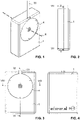
- FIG. 1 to 4 various exterior views of a first embodiment of a turbomachine according to the invention are shown.
- the turbomachine has a very compact, cuboid shape overall.
- the shape of the turbomachine is similar to that of a conventional cigarette box.
- This cassette-like design not only enables the flow machine to be easily inserted and removed from the ventilator, but also allows a large number of flow machines of this type to be stored in a space-saving manner. As a result, the turbomachines can in particular be stacked.
- the first embodiment of a turbomachine shown has a cuboid housing 1 which is constructed in one piece as a whole. From the outside, only a circular opening closed by a cover plate 4 and an inlet opening 15 and an outlet opening 16 can be seen on the housing 1 .
- the inlet port 15 and the outlet port 16 are arranged next to one another on a narrow end face of the housing 1 .
- the opening closed by the cover plate 4 is located on the large rear side of the housing 1.
- the outer dimensions of the housing are preferably 50x20x70 mm or 50x20x60 mm.
- a control and power supply cable 33 is led out of the housing 1 on the end face opposite the inlet opening 15 and the outlet opening 16 . This serves to supply a drive motor 3 arranged inside the housing with electrical energy. In addition, signals can be transmitted via the control and power supply cable 33 in order to control and monitor the drive motor 3 .
- the housing 1 is manufactured using additive manufacturing and can accordingly have a surface roughness that is increased compared to conventional manufacturing methods.
- the housing 1 has an interior 11 which is covered by the cover plate 4 towards the rear.
- the drive motor 3 with the impeller 2 attached thereto is arranged in the interior 11 .
- the drive motor 3 and the impeller 2 fill the interior space 11 almost completely.
- the interior 11 is delimited by inner surfaces of the housing 1 which are adapted to the outer shape of the impeller 2 .
- Radially adjacent to the impeller 2, the housing 1 forms a peripheral flow channel 14 which extends around the impeller 2 around.
- the drive motor 3 is an external rotor motor with a stator 31 and a rotor 32 surrounding it.
- the stator 31 is firmly attached to the cover plate 4 and is therefore stationary in relation to the housing 1.
- the rotor 32 rotates about an axis of rotation R, which extends perpendicularly to the outer surfaces of the front and rear of the housing 1.
- the drive motor 3 is preferably a brushless DC motor.
- the impeller 2 which can also be referred to as a fan wheel, is attached to the radial outside of the rotor 32.
- the impeller 2 is advantageously made in one piece as a whole and made of a plastic material, for example, by injection molding.
- the impeller 2 is preferably molded directly onto the radial outside of the rotor 32, more preferably directly onto the bell-shaped armature of the drive motor 3, ie the impeller 2 is already attached to the rotor 32 during its manufacture.
- an outflow channel 13 extends in the radial and, above all, tangential direction toward the outlet opening 16 . From the interior 11 to the outlet port 16 extends the Outflow channel 13 within the same, perpendicular to the axis of rotation R plane.
- the fluid conveyed by the impeller 2 passes from the interior 11 through the outflow channel 13 to the outlet opening 16.
- a breathing tube which leads to a patient can be connected to the outlet opening 16.
- An inflow channel 12 extends from the inlet opening 15 to the impeller 2 in such a way that the fluid sucked in through the inflow channel 12 impinges on the impeller 2 in the axial direction and centrally from the front with respect to the axis of rotation R.
- the inflow channel 12 extends from the inlet opening 15 first slightly towards the front side of the housing 1 and then in front of the outflow channel 13 and the interior space 11 towards the axis of rotation R (see FIG Figures 5-7 ).
- the inflow channel 12 tapers continuously up to the axis of rotation R. However, it widens in the directions perpendicular to it ( Figures 5 and 7 ). In the area of the axis of rotation R, the inflow channel 12 opens into the interior 11 in the axial direction.
- the fluid which can in particular be a gas such as air
- the fluid is sucked in by the rotating fan wheel 2 through the inlet opening 15 and into the inflow channel 12 .
- the fluid then passes through the inflow channel 12 to the front of the impeller 2.
- the fluid flowing in through the inflow channel 12 is deflected by approx. 90° so that it hits the front of the impeller 2 centrally and is caught by it becomes.
- the axially inflowing fluid is again deflected by about 90° by the impeller 2 and conveyed outwards in the radial direction. From there it gets into the peripheral flow channel 14 and via this into the outflow channel 13 .
- the fluid is ejected from the housing 1 through the outflow channel 13 and the outlet opening 16 .
- Both the inflow channel 12 and the outflow channel 13 thus each extend completely inside the housing 1 and together with the interior 11 form a relatively complex three-dimensional structure.
- Such a complex structure of the housing 1 could not easily be realized in one piece using conventional manufacturing methods and in particular using manufacturing methods based on casting molds.
- additive manufacturing makes this possible and thus enables an even more compact, optimal design of the housing 1.
- the parallel arrangement of the inlet opening 15 and the outlet opening 16 enables a particularly space-saving arrangement of connection lines. Since the fluid flow is deflected both in the inflow channel 12 and in the outflow channel 13 , the impeller 2 is not visible either through the inlet port 15 or through the outlet port 16 . As a result, the sound generated by the impeller 2 cannot travel directly to the outside, but is reflected several times in the interior of the housing 1 and thereby at least partially absorbed, which results in a clearly perceptible reduction in sound to the outside.
- the housing 1 of the present embodiment has cavities 18 .
- the cavities 18 are each completely surrounded by the material of the housing 1, which is easy to do due to additive manufacturing in production.
- the cavities 18 allow savings in material and thus enable a more cost-effective and lighter housing 1.
- the cavities can also serve to reduce noise emissions from the turbomachine.
- the cavities are advantageously partially or completely filled with a powder that has a vibration- or sound-absorbing effect. This is preferably the additive powder that is used anyway in the additive manufacturing process for the housing 1 . Instead of the additive powder being blown out of the areas of the cavities 18 during production, it preferably remains there. In this way, a particularly low-vibration and quiet turbomachine can be achieved with little manufacturing effort.
- the impeller 2 is particularly in the Figures 9 to 11 clearly visible. It has a circular base plate 21 which has a central opening in which the drive motor 3 is arranged.
- the base plate 21 is curved slightly forward towards the center or towards the opening.
- the base plate 22 can have a thickening, or as shown in FIGS Figures 9 and 10 recognizable, merge into a retaining ring 23, which establishes the connection to the rotor 32 of the drive motor 3.
- blades 22 are attached at regular intervals, each extending from the retaining ring 23 to the outer edge of the base plate 21.
- the blades 22 each have an approximately constant height along their extension from the inner to the outer edge of the base plate 21 . Due to the curvature of the base plate 21, the blades 22 rise slightly towards the front in each case.
- the blades 22 are curved backwards, which means that during operation of the turbomachine, ie when the impeller 2 rotates, they are each curved backwards from the center of the base plate 21 outwards with respect to the direction of rotation. In the view of figure 11 the impeller 2 thus rotates counterclockwise as intended. Due to the backward-curved blades 22, the impeller is designed to generate a particularly high pressure during operation.
- a second embodiment of an inventive turbomachine is in the Figures 12 to 15 shown.
- the embodiment of Figures 12 to 15 differs from that of Figures 1 to 11 that the outlet port 16 is not arranged parallel to the inlet port 15 here, but is directed in the axial direction.
- the outlet opening 16 is bordered by an outlet nozzle 17 which extends away from the rear of the housing 1 parallel to the axis of rotation R but spaced therefrom.
- the inlet opening 15 and the outlet opening 16 therefore point in two mutually perpendicular directions.
- the provision of the connecting piece 17 facilitates the coupling of, for example, a breathing tube to the outlet opening 16.
- the present embodiment differs from that of FIG Figures 1 to 11 that in the area of the inlet mouth a HEPA filter 6 is provided.
- the HEPA filter 6 is a particle filter that prevents particles such as dust etc. from penetrating into the interior of the housing 1 .
- an electronic unit 5 is additionally arranged in the interior 11 .
- the electronics unit 5 attached to the cover plate 4 is used to activate and control the drive motor 3.
- the electronics unit 5 can also contain sensors, for example for measuring the rotational speed, the temperature and/or vibrations.
- the electronics unit 5 could also have an RFID or a wireless connection unit, such as a Bluetooth unit, for example, in order to enable identification by the ventilator, for example so that only a specific type of flow machine can be connected.
- an energy store such as one or more batteries, could also be arranged in the interior 11 and attached to the cover plate 4 in order to supply the drive motor 3 with electrical energy.
- the housing 1 here has a plurality of boreholes 19 running through from the front to the rear, which are used to fasten the turbomachine, for example in a ventilator.
- nails or screws which are made of an elastic rubber material, are preferably passed through the boreholes 19 for fastening.
- elastic nails are known for use in the field of fans.
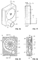
- the Figures 16 to 22 show another embodiment, which is essentially that of Figures 12 to 15 corresponds, but has an impeller 2 with a cover disk 24 .
- the attached to the front of the impeller 2 on the blades 22 cover plate 24 is in the Figures 19 to 22 recognizable. Due to the cover disk 24, the flow channels between the blades 22 are not only limited to the rear and sides, but also to the front, which means that there is less turbulence around the area of the impeller during operation.
- FIG. 23 to 25 Another fourth embodiment of a turbomachine according to the invention is Figures 23 to 25 shown.
- This embodiment essentially corresponds to that of FIG Figures 1 to 11 , but here no cavities 18, but drill holes 19 are provided.
- the boreholes 19 are used to attach the turbomachine to a ventilator, for example.
- fastening means such as nails or screws, which can be made in particular from an elastic rubber material, can be passed through the boreholes 19 .
- the cavities 18 are in the embodiment of Figures 23 to 25 in contrast to that of Figures 1 to 11 material reductions in the form of recesses are provided in the upper corner areas around the boreholes 19 . In this way, the consumption of material during manufacture can be reduced and the housing 1 can be manufactured more easily.
- the Figures 26 to 29 show a fifth embodiment of a turbomachine according to the invention, which is explained below on the basis of the differences from the embodiment of FIG Figures 1 to 11 is described.
- the case 1 is here with less material made and therefore lighter than the housing of the embodiment of Figures 1 to 11 . This is achieved by the upper corner areas being rounded along the interior 11 .
- the inlet port 15 and the outlet port 16 are each formed within a nozzle, thereby reducing the consumption of material around each of the two nozzles.
- the connectors also have the advantage that the coupling of hoses is made easier. For example, a fresh air supply hose can be coupled to the inlet connection and a breathing hose can be coupled to the outlet connection 17 . Due to the additive manufacturing, the shape of the housing 1 is particularly easy to adapt.
- the invention described here is not limited to the embodiments mentioned and a large number of modifications are possible.
- the drive motor outside the turbomachine or outside the housing.
- the flow channels extending inside the housing could also run differently and/or their number could be greater.
- the impeller may have any configuration other than that suggested in the above embodiments.
- the blades could also be curved forward or not curved at all.
- the flow machines shown in the exemplary embodiments are each radial flow machines.
- the turbomachine could also be an axial turbomachine, in which the fluid flows along the axis of rotation into the housing and to the impeller and leaves the housing again along the axis of rotation.
- the housing and the impeller would each have completely different configurations than those described in relation to the above exemplary embodiments. It would also be conceivable, for example, to provide connection pins on the outside of the housing instead of the control and energy supply cable 33 in order to enable the transmission of electrical energy and/or signals. A large number of other modifications are conceivable.
Landscapes
- Engineering & Computer Science (AREA)
- Mechanical Engineering (AREA)
- General Engineering & Computer Science (AREA)
- Manufacturing & Machinery (AREA)
- Chemical & Material Sciences (AREA)
- Materials Engineering (AREA)
- Structures Of Non-Positive Displacement Pumps (AREA)
Abstract
Es wird eine Strömungsmaschine angegeben, die ein Gehäuse (1) mit zumindest einem Strömungskanal (12, 13, 14), ein im Gehäuse (1) angeordnetes Laufrad (2) sowie einen Antriebsmotor (3) aufweist. Der Antriebsmotor dient zum Antreiben des Laufrads (2), um ein Fluid, durch den zumindest einen Strömungskanal (12, 13, 14) hindurch in das Gehäuse (1) hinein anzusaugen und/oder durch den zumindest einen Strömungskanal (12, 13, 14) hindurch aus dem Gehäuse (1) hinaus zu befördern. Das Gehäuse (1) ist mittels additiver Fertigung hergestellt. Des Weiteren wird eine Strömungsmaschine angegeben, bei der das Laufrad (2) im Spritzgussverfahren hergestellt und direkt an den Rotor (32) eines als Aussenläufer-Motor ausgebildeten Antriebsmotors (3) angespritzt ist.
Description
- Die vorliegende Erfindung betrifft eine Strömungsmaschine zum Ansaugen und Befördern eines Fluids, wie insbesondere eines Gases. Die Strömungsmaschine kann zum Beispiel zur Erzeugung eines Fluidstroms, zur Fluidabsaugung und/oder zur Erzeugung eines Über- oder Unterdrucks dienen.
- Strömungsmaschinen sind seit langem bekannt und werden in unterschiedlichsten Anwendungen eingesetzt. Die im Rahmen dieses Schutzrechts betreffenden Strömungsmaschinen weisen ein üblicherweise elektrisch angetriebenes Laufrad auf, welches in einem Gehäuse rotiert. Dadurch wird ein Fluid angesaugt, verdichtet und befördert. Je nach Art der Strömungsmaschine kann es sich beim Fluid zum Beispiel um ein Gas, wie insbesondere Luft, oder um eine Flüssigkeit handeln. Falls das Fluid ein Gas ist, wird die Strömungsmaschine üblicherweise als Ventilator oder Verdichter bezeichnet. Während Ventilatoren zwischen Ansaug- und Druckseite ein Druckverhältnis zwischen 1 und 1.3 erzielen, erreichen die als Verdichter benannten Strömungsmaschinen ein Druckverhältnis von grösser als 1.3. Im allgemeinen Sprachgebrauch werden Ventilatoren und Verdichter oft auch als Lüfter oder Gebläse bezeichnet.
- Strömungsmaschinen in Form von Ventilatoren und Verdichtern werden insbesondere zur Beatmung von Patienten eingesetzt, wie zum Beispiel bei der CPAP(Continuous Positive Airway Pressure)-Beatmung. Bei der CPAP-Beatmung, welche zum Beispiel in der Intensiv- und Notfallmedizin, aber auch als Therapie bei Schlafapnoe angewandt wird, wird die Atmung des Patienten mit einem konstanten Luftüberdruck unterstützt.
- Eine Strömungsmaschine zur Verwendung in einem CPAP-Gerät ist beispielsweise in der
WO 2006/045602 A1 offenbart. Die einfach austauschbare Strömungsmaschine weist ein Lüfterrad zur Erzeugung des Überdrucks auf, welches an einen Elektromotor gekoppelt und in einem mehrteiligen Gehäuse aufgenommen ist. - Die
DE 83 31 997.2 U1 offenbart einen Gleichstromkleinstventilator mit einem Aussenläufermotor, auf dessen Aussenmantel ein Laufrad aufgeklebt oder aufgeschrumpft ist. - Die
EP 2 072 832 A2 offenbart einen Miniaturlüfter zur Kühlung von technischen Bauteilen, wie zum Beispiel Leiterplatten. Der Lüfter weist einen Motor mit einem Aussenrotor auf, an dem ein Lüfterrad befestigt ist. - Bei der Vorrichtung der
EP 2 020 736 A2 ist ein Lüfterrad mittels Schrauben am aussenseitigen Rotor eines bürstenlosen Motors befestigt. - Die
US 2008/0226472 A1 offenbart einen Lüfter, bei dem das Lüfterrad zusammen mit dem Antriebsmotor in einem kassettenförmigen, mehrteiligen Gehäuse untergebracht sind. Im Inneren des Gehäuses sind Strömungskanäle ausgebildet, die zum Ansaugen und Ausblasen der vom Lüfterrad beförderten Luft dienen. - Die
CN 105090118 A1 offenbart eine Wasserpumpe mit einem kassettenartigen Gehäuse, in dessen Inneren ein Impeller zur Beförderung des Wassers angeordnet ist. Das Gehäuse weist Strömungskanäle zum Zu- und Abführen des Wassers auf. Indem ein Kanalteil beweglich ausgebildet ist, lässt sich das Gehäuse mit unterschiedlichen Impellern kombinieren. - Es ist also eine Aufgabe der vorliegenden Erfindung, eine effiziente Strömungsmaschine anzugeben, die einfach und kostengünstig herstellbar ist. Zur Lösung dieser Aufgabe wird eine Strömungsmaschine vorgeschlagen, wie sie in Anspruch 1 angegeben ist. Eine weitere Strömungsmaschine, welche diese Aufgabe löst, ist in Anspruch 15 angegeben. Vorteilhafte Ausführungsformen sind in den abhängigen Ansprüchen angegeben.
- Die vorliegende Erfindung stellt also eine Strömungsmaschine, insbesondere ein Ventilator oder Verdichter, zur Verfügung, aufweisend
- ein Gehäuse mit zumindest einem Strömungskanal;
- ein im Gehäuse angeordnetes Laufrad; sowie
- einen Antriebsmotor zum Antreiben des Laufrads in einer Drehbewegung um eine Rotationsachse, um ein Fluid, insbesondere ein Gas, durch den zumindest einen Strömungskanal hindurch in das Gehäuse hinein anzusaugen und/oder durch den zumindest einen Strömungskanal hindurch aus dem Gehäuse hinaus zu befördern.
Das Gehäuse ist erfindungsgemäss mittels additiver Fertigung hergestellt. - Die additive Fertigung ermöglicht es nicht nur, das Gehäuse auf einfache Art und Weise herzustellen, sondern erlaubt auch die Ausbildung von komplexen dreidimensionalen Strukturen am Gehäuse. So können der eine oder die mehreren Strömungskanäle problemlos gerundete Flächen und/oder Kurven aufweisen und auch vollständig im Gehäuseinneren verlaufen, das heisst Abschnitte aufweisen, welche im Querschnitt vollständig vom Material des Gehäuses umschlossen sind. Das Gehäuse kann aufgrund der Herstellung mittels additiver Fertigung auch Hinterschnitte und/oder Hohlräume aufweisen, was bei konventionellen Herstellungsmethoden einstückig nicht oder nur mit erheblichem Zusatzaufwand möglich wäre. Des Weiteren ermöglicht die additive Fertigung nicht nur die parallele Herstellung einer Vielzahl von Gehäusen gleichzeitig, sondern erlaubt auch eine sehr flexible Anpassung der Gehäuseform an spezielle Erfordernisse und/oder an Kundenwünsche. Aufgrund der additiven Fertigung ist auch die Herstellung von besonders klein dimensionierten, aber trotzdem dreidimensional komplizierten Strukturen möglich, so dass die Herstellung von besonders kleinen, aber trotzdem sehr effizienten Strömungsmaschinen möglich ist.
- Die additive Fertigung, auch 3D-Druck genannt, bezeichnet Fertigungsverfahren, bei denen Material schichtweise und vorteilhaft computergesteuert aufgetragen wird. Als Werkstoffe kommen zum Beispiel Kunststoffe, Kunstharze, Keramiken und Metalle in Frage, wobei die Werkstoffe bei der Fertigung in flüssiger oder fester Form (zum Beispiel als Pulver) aufgetragen werden können. Bei der Fertigung finden vorteilhaft beim Auftragen oder unmittelbar danach physikalische und/oder chemische Härtungs- oder Schmelzprozesse statt.
- Aufgrund der additiven Fertigung kann die Herstellung sehr einfach an unterschiedliche Gehäuseformen angepasst werden. Insbesondere müssen hierzu keine speziellen Werkzeuge, wie zum Beispiel Gussformen, angefertigt werden. Eine Anpassung lohnt sich deshalb auch für kleine Stückzahlen, so dass die Strömungsmaschine auf besonders einfache Art und Weise zum Beispiel bzgl. ihrer Leistung re-dimensioniert werden kann oder an spezielle Erfordernisse und/oder an Kundenwünsche anpassbar ist.
- Indem das Gehäuse eine komplexe dreidimensionale Struktur mit zum Beispiel Hinterschnitten, Hohlräumen und/oder komplett im Inneren verlaufenden Strömungskanälen mit Biegungen, Kurven etc. aufweisen kann, ist eine besonders gute Optimierung der Strömungsmaschine bzgl. hydro- oder aerodynamischen Erfordernissen und/oder bzgl. schalltechnischen Vorgaben möglich. Auch die Kammer, in welcher das Laufrad angeordnet ist, kann bzgl. der Form ihrer Innenflächen optimal an hydro- bzw. aerodynamische Erfordernisse angepasst werden. Die Möglichkeit von Hohlräumen kann benutzt werden, um zum Beispiel bei der Herstellung den Materialverbrauch oder das Gewicht der Strömungsmaschine zu reduzieren. Es können aber zum Beispiel auch gezielt Hohlräume geschaffen werden, um das Schallverhalten des Gehäuses bzw. der Strömungsmaschine positiv zu beeinflussen. Der oder die erwähnten Hohlräume können dabei vollständig im Gehäuseinneren angeordnet sein, das heisst vollständig vom Material des Gehäuses umschlossen sein. Gemäss einer Weiterbildung der Erfindung können der oder die Hohlräume teilweise oder ganz mit einem Pulver ausgefüllt sein. Es hat sich herausgestellt, dass das Pulver in den Hohlräumen zu einer deutlichen Reduktion von Vibrationen und Schallemissionen führt. Beim Pulver kann es sich insbesondere um das Additiv-Pulver handeln, welches zur additiven Fertigung des Gehäuses verwendet wird, das aber im Bereich der Hohlräume nicht gehärtet bzw. geschmolzen wird, sondern in Pulverform in den Hohlräumen verbleibt. Die Herstellung einer Strömungsmaschine mit geringen Schallemissionen wird dadurch besonders einfach.
- Bei der Strömungsmaschine handelt es sich bevorzugt um einen Ventilator oder Verdichter zur Förderung eines Gases, wie insbesondere Luft. Insbesondere kann es sich um eine radiale Strömungsmaschine handeln, bei der das Fluid im unmittelbaren Bereich des Laufrades axial bzw. parallel zur Rotationsachse angesaugt wird. Der Fluidstrom wird bei der radialen Strömungsmaschine durch die Rotation des Laufrades um 90° umgelenkt und in radialer Richtung vom Laufrad aus weg befördert, um dann durch einen Gasauslass hindurch nach aussen hin ausgeblasen zu werden. Mit anderen Worten kann das Laufrad insbesondere dazu ausgebildet sein, den Fluidstrom bzgl. der Rotationsachse von einer axialen Richtung in eine radiale Richtung umzulenken. Radiale Strömungsmaschinen ermöglichen bei vorgegebener Luftmenge üblicherweise die Erzeugung eines verhältnismässig grossen Druckes. Zudem kann es sich beim Strömungskanal oder bei zumindest einem der Strömungskanäle insbesondere um einen Einströmungskanal handeln, der sich (zumindest im Abschnitt unmittelbar stromaufwärts zum Laufrad) derart zum Laufrad hin erstreckt, dass das durch den Einströmungskanal angesaugte Fluid bzgl. der Rotationsachse in axialer Richtung und zentral auf das Laufrad auftrifft. Grundsätzlich wäre es aber auch möglich, dass die Strömungsmaschine eine axiale Strömungsmaschine ist, bei welcher der Fluidstrom in axialer Richtung bzgl. der Rotationsachse in das Gehäuse hinein und zum Laufrad hin sowie in axialer Richtung vom Laufrad weg und aus dem Gehäuse hinaus strömt.
- Im Vergleich zu herkömmlichen Herstellungsarten weisen Bauteile, die mittels additiver Fertigung hergestellt sind, üblicherweise eine etwas erhöhte Oberflächenrauheit auf. Es wurde überraschenderweise festgestellt, dass dies je nachdem beim Gehäuse der erfindungsgemässen Strömungsmaschine gewisse Vorteile mit sich bringen kann: Aufgrund der erhöhten Oberflächenrauheit der Gehäuseinnenflächen, wie zum Beispiel im Bereich der Laufradkammer und der Strömungskanäle, entstehen am Rand des Fluidstroms kleine Verwirbelungen. Innerhalb dieser Verwirbelungen kann das Fluid aber weiterhin weitgehend laminar strömen. Insbesondere an schalltechnisch heiklen Stellen, wie zum Beispiel im Bereich der Einlass- und Auslassmündungen, führen die Verwirbelungen aber zu einer deutlichen Reduktion von Schwingungen am Gehäuse. Die erhöhte Oberflächenrauheit kann deshalb unerwarteterweise insgesamt zu einer Reduktion der Schallemissionen im Betrieb der Strömungsmaschine führen. Die erhöhte Oberflächenrauheit führt ausserdem dazu, dass der Schall im Inneren des Gehäuses vermehrt diffus, das heisst in verschiedene Richtungen, reflektiert und aufgrund der grösseren Oberfläche eher absorbiert wird.
- Aufgrund der additiven Fertigung hat das Gehäuse üblicherweise somit im Vergleich zu herkömmlichen Herstellungsarten eine etwas erhöhte Oberflächenrauheit. Zudem sind bei genauerer Betrachtung, allenfalls bei Vergrösserung oder gar unter dem Mikroskop, die bei der Fertigung aufgetragenen Schichten auch am fertig herstellten Gehäuse meist noch sichtbar. Des Weiteren kann ein Fachmann oft auch anhand der Komplexität der dreidimensionalen Form des Gehäuses die Herstellung mittels additiver Fertigung erkennen. An der fertig hergestellten Strömungsmaschine ist die additive Fertigung des Gehäuses für einen Fachmann somit ohne Weiteres erkennbar.
- Der oder die Strömungskanäle verlaufen vorteilhaft zu einem Grossteil vollständig im Inneren des Gehäuses. Auch die Laufradkammer befindet sich bevorzugt zum einem Grossteil im Inneren des Gehäuses, das heisst ihre Innenflächen werden zu 50% oder mehr, bevorzugter zu 60% oder mehr, noch bevorzugter zu 70% oder mehr vom Gehäuse gebildet. Der oder die Strömungskanäle können insbesondere am Gehäuse angeformt sein. Vorzugsweise sind zumindest ein Einströmungskanal und ein Ausströmungskanal vorhanden. Der Einströmungskanal ist stromaufwärts und der Ausströmungskanal stromabwärts zum Laufrad angeordnet.
- Das Laufrad dient zur Beförderung des Fluids in der Strömungsmaschine. Wenn es sich beim beförderten Fluid um ein Gas, insbesondere um Luft, handelt, kann das Laufrad auch als Lüfterrad bezeichnet werden. Zur Beförderung des Fluids weist das Laufrad üblicherweise Laufradschaufeln auf, welche im Betrieb der Strömungsmaschine, das heisst bei Rotation des Laufrads um seine Rotationsachse, derart auf das Fluid in der Laufradkammer einwirken, dass dieses befördert wird. Im Bereich stromabwärts des Laufrades entsteht dadurch ein Überdruck, so dass das Fluid aus der Strömungsmaschine ausgestossen wird. Im Bereich stromaufwärts der Laufradkammer entsteht hingegen ein Unterdruck, wodurch weiteres Fluid angesogen wird. Das Laufrad ist hierzu an einen Rotor der Antriebsmaschine gekoppelt. Bevorzugt ist das Laufrad via eine Welle oder, noch bevorzugter, direkt am Rotor befestigt.
- Das Gehäuse ist bevorzugt als Ganzes einstückig hergestellt. Mit Ausnahme der Ein- und Auslässe der Strömungskanäle sowie einer allfälligen Öffnung zum Einsetzen des Laufrades und/oder des Antriebsmotors weist das Gehäuse vorzugsweise keine weiteren Öffnungen auf. Falls eine Öffnung zum Einsetzen des Laufrades und/oder des Antriebsmotors vorhanden ist, ist diese vorteilhaft mit einer Deckplatte verschliessbar. Die Deckplatte hat vorteilhaft als Ganzes eine einfache, plattenförmige Ausgestaltung. Grundsätzlich wäre aber eine Anordnung des Antriebsmotors auch ausserhalb des Gehäuses denkbar. Aufgrund der einstückigen Ausgestaltung des Gehäuses ist die Strömungsmaschine vorteilhaft mit besonders wenigen Bauteilen herstellbar. Bevorzugt weist die Strömungsmaschine lediglich das einstückig hergestellte Gehäuse, das Laufrad und den Antriebsmotor sowie allenfalls die Deckplatte auf. Optional kann die Strömungsmaschine noch eine Elektronikeinheit zur Ansteuerung des Antriebsmotors und/oder Energiespeicher, wie z.B. eine oder mehrere Batterien, aufweisen.
- Die Strömungsmaschine kann insbesondere zur künstlichen Beatmung bzw. zur Atmungsunterstützung ausgebildet sein. Insbesondere kann die Strömungsmaschine zur Verwendung in einem CPAP-Gerät ausgebildet sein. Eine mit der additiven Fertigung mögliche besonders kleine Dimensionierung der Strömungsmaschine kann es ermöglichen, dass sie nahe von Nase und/oder getragen bzw. angeordnet wird. Der Atemschlauch wird dadurch kurz und bewirkt einen tiefen Widerstand, so dass sich der Leistungsbedarf der Strömungsmaschine reduziert.
- Dank der möglichen kleinen und leichten Bauweise kann die Strömungsmaschine gemäss einer Weiterbildung der Erfindung insbesondere auch in einer Ganz-Gesichts-Maske (engl. Full-Face-Mask) zum Einsatz kommen. Aufgrund der additiven Fertigung ist das Gehäuse der Strömungsmaschine individuell an den jeweiligen Patienten anpassbar und kann dadurch besonders ergonomisch ausgestaltet werden. Auch die technischen Werte der Strömungsmaschine sind aufgrund der additiven Fertigung des Gehäuses besonders einfach anpassbar.
- Aufgrund ihrer besonders einfachen Herstellungsart kann die Strömungsmaschine insbesondere als Wegwerfkomponente konzipiert sein. Da dadurch die Anforderungen an die Lebensdauer der Strömungsmaschine reduziert werden, kann deren Herstellung erheblich vereinfacht und kostengünstiger gestaltet werden. Wenn die Strömungsmaschine zum Beispiel in einem CPAP-Gerät eingesetzt wird, kann dieses dazu ausgebildet sein, dem Benutzer z.B. nach einer gewissen Anzahl Betriebsstunden den notwendigen Ersatz der Strömungsmaschine anzuzeigen, ähnlich wie es dies z.B. bei Druckern in Bezug auf die Druckerpatronen seit längerem bekannt ist. Die Strömungsmaschine selbst kann dazu ausgebildet sein, dem Benutzer und/oder dem Beatmungsgerät z.B. den notwendigen Ersatz anzuzeigen, beispielsweise auf der Basis einer Betriebsstundenerfassung.
- Beim Strömungskanal oder bei zumindest einem der Strömungskanäle kann es sich insbesondere um einen Ausströmungskanal handeln, der sich bzgl. der Rotationsachse in tangentialer und/oder radialer Richtung vom Laufrad aus weg erstreckt und zum Befördern des Fluids aus dem Gehäuse hinaus dient. Vorteilhaft wird der Fluidstrom im Übergangsbereich zwischen Laufrad und Ausströmungskanal nicht umgelenkt. Bevorzugt erstreckt sich der Ausströmungskanal zumindest in einem ersten Abschnitt unmittelbar nach dem Laufrad, noch bevorzugter der gesamte Ausströmungskanal bis zur Auslassmündung, parallel zu einer senkrecht zur Rotationsachse stehenden Ebene. Der Fluidstrom wird dadurch weniger umgelenkt und erfährt entsprechend weniger Widerstand.
- In bestimmten Ausführungsformen kann es vorteilhaft sein, wenn der Ausströmungskanal bzgl. der Rotationsachse in tangentialer und/oder radialer Richtung vom Gehäuse aus nach aussen mündet. Bevorzugt erstreckt sich der Ausströmungskanal zumindest in einem Abschnitt unmittelbar vor der Auslassmündung parallel zu einer senkrecht zur Rotationsachse stehenden Ebene. Auf diese Weise wird der Fluidstrom im Bereich der Auslassmündung weniger umgelenkt, was weniger Widerstand und weniger Fluidverwirbelungen und damit weniger Schallemissionen mit sich bringt.
- In anderen Ausführungsformen kann es jedoch vorteilhaft sein, wenn der Ausströmungskanal bzgl. der Rotationsachse in axialer Richtung vom Gehäuse aus nach aussen mündet. Vorteilhaft in Bezug auf Schallemissionen ist die Auslassöffnung jedoch radial beabstandet von der Rotationsachse angeordnet. Die Auslassöffnung wird dabei bevorzugt von einem Auslassstutzen gebildet.
- Der Einströmungskanal mündet bevorzugt bzgl. der Rotationsachse in tangentialer und/oder radialer Richtung vom Gehäuse aus nach aussen. Bevorzugt erstreckt sich der Einströmungskanal zumindest in einem ersten Abschnitt unmittelbar nach der Einlassmündung, noch bevorzugter der gesamte Einströmungskanal bis zum Laufrad, parallel zu einer senkrecht zur Rotationsachse stehenden Ebene. Der Fluidstrom wird dadurch weniger umgelenkt und erfährt entsprechend weniger Widerstand.
- Bevorzugt hat das Gehäuse, noch bevorzugter die Strömungsmaschine als Ganzes, eine quaderförmige Gestalt. Das Gehäuse, bevorzugt die Strömungsmaschine als Ganzes, weist bevorzugt eine kompakte und vorteilhaft kassettenartige Form auf. Vorteilhaft sind die Abmessungen des Gehäuses in Richtung entlang der Rotationsachse um mindestens die Hälfte kleiner als jeweils in zwei senkrecht zur Rotationsachse stehende Raumrichtungen.
- Beim Antriebsmotor handelt es sich bevorzugt um einen Elektromotor mit einem bzgl. des Gehäuses ortsfesten Stators und einem im Betrieb rotierenden Rotor. Der Rotor rotiert dabei bevorzugt um die Rotationsachse des Laufrads. Der Elektromotor kann insbesondere ein bürstenloser Gleichstrommotor sein.
- Das Laufrad ist vorteilhaft als Ganzes einstückig hergestellt. Bevorzugt ist es im Spritzgussverfahren, vorteilhaft aus einem Kunststoffmaterial, hergestellt.
- Bei einer insbesondere bevorzugten Ausführungsform handelt es sich beim Antriebsmotor um einen Aussenläufer-Motor mit einem Stator und mit einem den Stator umgebenden Rotor. Das Laufrad ist dabei bevorzugt im Spritzgussverfahren hergestellt und fest am Rotor, vorteilhaft an der radialen Aussenfläche des Rotors, angebracht. Auf diese Weise kann das Drehmoment optimal vom Rotor auf das Laufrad übertragen werden, ohne dass eine Welle oder andere zusätzliche Bauteile notwendig sind. Die Massenträgheit der Rotor/Laufrad-Einheit kann dadurch minimiert werden, wodurch eine besonders grosse Dynamik der Strömungsmaschine erreicht werden kann.
- Insbesondere bevorzugt ist eine Ausführungsform, bei der das Laufrad direkt an den Rotor des Aussenläufer-Motors angespritzt ist. Das Laufrad ist dadurch besonders fest mit dem Rotor verbunden. Ausserdem vereinfacht sich die Herstellung, da das Laufrad bereits bei seiner Herstellung am Motor angebracht wird und dementsprechend keine weiteren Schritte zur Kopplung des Laufrads an den Motor notwendig sind. Die Auswuchtung kann dann für den Antriebsmotor und das Laufrad gemeinsam erfolgen. Das Laufrad kann direkt an die radiale Aussenfläche des Rotors angespritzt sein. Insbesondere kann das Laufrad direkt an den Glockenanker des Aussenläufer-Motors angespritzt sein.
- Das Gehäuse weist bevorzugt einen Innenraum zur Aufnahme des Antriebsmotors und des Laufrads auf. Der Antriebsmotor ist dann vorteilhaft an einer Deckplatte angebracht, welche zum Verschliessen des Innenraums nach aussen hin dient. Beim Einsetzen des Antriebsmotors mit dem daran angebrachten Laufrad in den Innenraum wird dann also vorteilhaft gleichzeitig der Innenraum mit der Deckplatte verschlossen. Die Herstellung der Strömungsmaschine wird dadurch weiter vereinfacht. Wenn der Innenraum bestimmungsgemäss durch die Deckplatte verschlossen ist, weist das Gehäuse mit Ausnahme einer oder mehrerer Einlassmündungen sowie einer oder mehrerer Auslassmündungen für das Fluid keine weiteren Öffnungen auf.
- Die Strömungsmaschine kann ausserdem eine zur Steuerung des Antriebmotors dienende Elektronikeinheit aufweisen, welche insbesondere im Innenraum des Gehäuses angeordnet und vorteilhaft an der Deckplatte angebracht ist.
- Das Laufrad weist bevorzugt rückwärtsgekrümmte Schaufeln auf. Dadurch können besonders hohe Drücke sowie ein hoher Wirkungsgrad erreicht werden.
- Die Strömungsmaschine kann ausserdem einen Partikelfilter, insbesondere einen HEPA-Filter, aufweisen, welcher im Bereich des Strömungskanals oder von zumindest einem der Strömungskanäle angeordnet ist. Besonders bevorzugt ist der Partikelfilter im Bereich der Einlassmündung des Einströmkanals angeordnet, so dass das Laufrad bzw. der mit Atemluft zu versorgende Patient vor Partikeln geschützt ist.
- Die vorliegende Erfindung bezieht sich ausserdem auf eine Strömungsmaschine, insbesondere Ventilator oder Verdichter, welche bevorzugt wie oben ausgeführt ausgebildet ist und aufweist:
- ein Laufrad; sowie
- einen als Aussenläufer-Motor ausgebildeten Antriebsmotor mit einem Stator und mit einem den Stator umgebenden Rotor zum Antreiben des Laufrads in einer Drehbewegung um eine Rotationsachse, um ein Fluid, insbesondere ein Gas, anzusaugen und zu befördern.
Das Laufrad ist im Spritzgussverfahren hergestellt und direkt an den Rotor, insbesondere an die radiale Aussenseite des Rotors, angespritzt. - Die Strömungsmaschine kann, muss aber nicht, ein wie oben ausgeführt mittels additiver Fertigung hergestelltes Gehäuse mit Strömungskanälen aufweisen. Die Strömungsmaschine mit dem an den Rotor des Aussenläufer-Motors angespritzten Laufrad kann genauso gut auch ein herkömmlich hergestelltes Gehäuse aufweisen.
- Bevorzugte Ausführungsformen der Erfindung werden im Folgenden anhand der Zeichnungen beschrieben, die lediglich zur Erläuterung dienen und nicht einschränkend auszulegen sind. In den Zeichnungen zeigen:
- Fig. 1
- eine perspektivische Ansicht von schräg hinten einer ersten Ausführungsform einer erfindungsgemässen Strömungsmaschine;
- Fig. 2
- eine Ansicht der Strömungsmaschine der
Fig. 1 von der Seite; - Fig. 3
- eine Ansicht der Rückseite der Strömungsmaschine der
Fig. 1 ; - Fig. 4
- eine Ansicht der Vorderseite der Strömungsmaschine der
Fig. 1 ; - Fig. 5
- eine zentrale Schnittansicht entlang der in der
Fig. 2 angegebenen Ebene V-V der Strömungsmaschine derFig. 1 ; - Fig. 6
- eine zentrale Schnittansicht entlang der in der
Fig. 3 angegebenen Ebene VI-VI der Strömungsmaschine derFig. 1 ; - Fig. 7
- eine Schnittansicht entlang der in der
Fig. 2 angegebenen Ebene VII-VII der Strömungsmaschine derFig. 1 ; - Fig. 8
- eine Schnittansicht entlang der in der
Fig. 3 angegebenen Ebene VIII-VIII der Strömungsmaschine derFig. 1 ; - Fig. 9
- eine perspektivische Ansicht des am Antriebsmotor angebrachten Laufrads der Strömungsmaschine der
Fig. 1 , inkl. Deckplatte; - Fig. 10
- eine Ansicht des am Antriebsmotor angebrachten Laufrads der Strömungsmaschine der
Fig. 1 , inkl. Deckplatte, von der Seite; - Fig. 11
- eine Ansicht des am Antriebsmotor angebrachten Laufrads der Strömungsmaschine der
Fig. 1 , inkl. Deckplatte, von vorne; - Fig. 12
- eine perspektivische Ansicht von schräg hinten einer zweiten Ausführungsform einer erfindungsgemässen Strömungsmaschine;
- Fig. 13
- eine Ansicht der Strömungsmaschine der
Fig. 12 von der Seite; - Fig. 14
- eine zentrale Schnittansicht entlang der in der
Fig. 13 angegebenen Ebene XIV-XIV der Strömungsmaschine derFig. 12 ; - Fig. 15
- eine zentrale Schnittansicht entlang der in der
Fig. 14 angegebenen Ebene XV-XV der Strömungsmaschine derFig. 12 ; - Fig. 16
- eine perspektivische Ansicht von schräg hinten einer dritten Ausführungsform einer erfindungsgemässen Strömungsmaschine;
- Fig. 17
- eine Ansicht der Strömungsmaschine der
Fig. 16 von der Seite; - Fig. 18
- eine zentrale Schnittansicht entlang der in der
Fig. 17 angegebenen Ebene XVIII-XVIII der Strömungsmaschine derFig. 16 ; - Fig. 19
- eine zentrale Schnittansicht entlang der in der
Fig. 18 angegebenen Ebene XIX-XIX der Strömungsmaschine derFig. 16 ; - Fig. 20
- eine perspektivische Ansicht des am Antriebsmotor angebrachten Laufrads der Strömungsmaschine der
Fig. 16 , inkl. Deckplatte; - Fig. 21
- eine Ansicht des am Antriebsmotor angebrachten Laufrads der Strömungsmaschine der
Fig. 16 , inkl. Deckplatte, von der Seite; - Fig. 22
- eine Ansicht des am Antriebsmotor angebrachten Laufrads der Strömungsmaschine der
Fig. 16 , inkl. Deckplatte, von vorne; - Fig. 23
- eine perspektivische Ansicht von schräg hinten einer vierten Ausführungsform einer erfindungsgemässen Strömungsmaschine;
- Fig. 24
- eine zentrale Schnittansicht der Strömungsmaschine der
Fig. 23 ; - Fig. 25
- eine zentrale Schnittansicht entlang der in der
Fig. 24 angegebenen Ebene XXV-XXV der Strömungsmaschine derFig. 23 ; - Fig. 26
- eine perspektivische Ansicht von schräg hinten einer fünften Ausführungsform einer erfindungsgemässen Strömungsmaschine;
- Fig. 27
- eine Ansicht der Strömungsmaschine der
Fig. 26 von der Seite; - Fig. 28
- eine zentrale Schnittansicht entlang der in der
Fig. 27 angegebenen Ebene XXIV-XXIV der Strömungsmaschine derFig. 26 ; sowie - Fig. 29
- eine zentrale Schnittansicht entlang der in der
Fig. 28 angegebenen Ebene XXIX-XXIX der Strömungsmaschine derFig. 26 . - In den
Figuren 1 bis 29 sind verschiedene bevorzugte Ausführungsformen von erfindungsgemässen Strömungsmaschinen gezeigt, welche jeweils zum Befördern eines Gases, insbesondere Luft, in einem Beatmungsgerät dienen. Beim Beatmungsgerät handelt es sich bevorzugt um ein CPAP-Gerät. Elemente, die eine gleiche oder zumindest ähnliche Funktion erfüllen, aber zu unterschiedlichen Ausführungsformen gehören, sind jeweils mit denselben Bezugszeichen versehen. - In den
Figuren 1 bis 4 sind verschiedene Aussenansichten einer ersten Ausführungsform einer erfindungsgemässen Strömungsmaschine gezeigt. Wie aus diesen Figuren gut ersichtlich ist, weist die Strömungsmaschine insgesamt eine sehr kompakte, quaderförmige Gestalt auf. Die Form der Strömungsmaschine ist derjenigen einer üblichen Zigarettenschachtel ähnlich. Diese kassettenartige Bauweise ermöglicht nicht nur ein einfaches Einsetzen und Entnehmen der Strömungsmaschine in bzw. aus dem Beatmungsgerät, sondern auch eine platzsparende Lagerung einer Vielzahl von derartigen Strömungsmaschinen. Die Strömungsmaschinen sind dadurch insbesondere stapelbar. - Die in den
Figuren 1 bis 8 gezeigte erste Ausführungsform einer Strömungsmaschine weist ein quaderförmiges, als Ganzes einstückig ausgebildetes Gehäuse 1 auf. Am Gehäuse 1 sind von aussen her lediglich eine durch eine Deckplatte 4 verschlossene kreisrunde Öffnung sowie eine Einlassmündung 15 und eine Auslassmündung 16 erkennbar. Die Einlassmündung 15 und die Auslassmündung 16 sind nebeneinander an einer schmalen Stirnseite des Gehäuses 1 angeordnet. Die von der Deckplatte 4 verschlossene Öffnung befindet sich an der grossflächigen Rückseite des Gehäuses 1. - Die Aussenabmessungen des Gehäuses betragen bevorzugt 50x20x70 mm oder 50x20x60 mm.
- Auf der der Einlassmündung 15 und der Auslassmündung 16 gegenüberliegenden Stirnseite ist ein Steuerungs- und Energieversorgungskabel 33 aus dem Gehäuse 1 herausgeführt. Dieses dient zur Versorgung eines im Gehäuseinnern angeordneten Antriebsmotors 3 mit elektrischer Energie. Ausserdem können über das Steuerungs- und Energieversorgungskabel 33 Signale übertragen werden, um den Antriebsmotor 3 anzusteuern und zu kontrollieren.
- Das Gehäuse 1 ist mittels additiver Fertigung hergestellt und kann dementsprechend eine Oberflächenrauheit aufweisen, die im Vergleich zu herkömmlichen Herstellverfahren erhöht ist.
- Das Gehäuse 1 weist einen Innenraum 11 auf, welcher zur Rückseite hin von der Deckplatte 4 abgedeckt ist. Im Innenraum 11 ist der Antriebsmotor 3 mit daran angebrachtem Laufrad 2 angeordnet. Der Antriebsmotor 3 und das Laufrad 2 füllen den Innenraum 11 beinahe vollständig aus. Der Innenraum 11 wird von Innenflächen des Gehäuses 1 begrenzt, die an die Aussenform des Laufrads 2 angepasst sind. Radial angrenzend an das Laufrad 2 bildet das Gehäuse 1 einen peripheren Strömungskanal 14, der sich um das Laufrad 2 herum erstreckt.
- Beim Antriebsmotor 3 handelt es sich um einen Aussenläufer-Motor mit einem Stator 31 und einem diesen umgebenden Rotor 32. Der Stator 31 ist fest an der Deckplatte 4 angebracht und dadurch ortsfest in Bezug auf das Gehäuse 1. Im Betrieb der Strömungsmaschine rotiert der Rotor 32 um eine Rotationsachse R, die sich senkrecht zu den Aussenflächen der Vorder- und Rückseite des Gehäuses 1 erstreckt. Der Antriebsmotor 3 ist bevorzugt ein bürstenloser Gleichstrommotor.
- Das Laufrad 2, welches auch als Lüfterrad bezeichnet werden kann, ist an der radialen Aussenseite des Rotors 32 angebracht. Vorteilhaft ist das Laufrad 2 als Ganzes einstückig und im Spritzgussverfahren zum Beispiel aus einem Kunststoffmaterial hergestellt. Bevorzugt ist das Laufrad 2 dabei direkt an die radiale Aussenseite des Rotors 32, noch bevorzugter direkt an den Glockenanker des Antriebsmotors 3 angespritzt, das heisst das Laufrad 2 wird bereits bei seiner Herstellung am Rotor 32 angebracht.
- Vom Innenraum 11 und vom peripheren Strömungskanal 14 aus erstreckt sich ein Ausströmungskanal 13 in radialer und vor allem tangentialer Richtung zur Auslassmündung 16 hin. Vom Innenraum 11 bis zur Auslassmündung 16 erstreckt sich der Ausströmungskanal 13 innerhalb derselben, senkrecht zur Rotationsachse R stehenden Ebene. Im Betrieb der Strömungsmaschine gelangt das vom Laufrad 2 beförderte Fluid vom Innenraum 11 durch den Ausströmungskanal 13 hindurch zur Auslassmündung 16. An der Auslassmündung 16 kann ein Beatmungsschlauch angeschlossen sein, welcher zu einem Patienten führt.
- Von der Einlassmündung 15 aus erstreckt sich ein Einströmungskanal 12 derart zum Laufrad 2 hin, dass das durch den Einströmungskanal 12 angesaugte Fluid bzgl. der Rotationsachse R in axialer Richtung und zentral von der Vorderseite her auf das Laufrad 2 auftrifft. Der Einströmungskanal 12 erstreckt sich hierzu von der Einlassmündung 15 her zuerst leicht zur Vorderseite des Gehäuses 1 hin und anschliessend vor dem Ausströmungskanal 13 und dem Innenraum 11 zur Rotationsachse R hin (siehe
Figuren 5-7 ). In Richtung von der Vorder- zur Rückseite des Gehäuses 1 betrachtet (Figuren 6, und 8 ), verjüngt sich der Einströmungskanal 12 kontinuierlich bis zur Rotationsachse R. In die dazu senkrecht stehenden Richtungen verbreitert er sich jedoch (Figuren 5 und 7 ). Im Bereich der Rotationsachse R mündet der Einströmungskanal 12 in axialer Richtung in den Innenraum 11. - Im Betrieb der Strömungsmaschine wird das Fluid, bei welchem es sich insbesondere um ein Gas, wie zum Beispiel Luft, handeln kann, vom sich drehenden Lüfterrad 2 durch die Einlassmündung 15 hindurch in den Einströmungskanal 12 hinein angesogen. Das Fluid gelangt dann durch den Einströmungskanal 12 hindurch zur Vorderseite des Laufrads 2. Im Bereich der Rotationsachse R wird das durch den Einströmungskanal 12 einströmende Fluid um ca. 90° umgelenkt, so dass es zentral auf die Vorderseite des Laufrades 2 auftrifft und von diesem erfasst wird. Vom Laufrad 2 wird das axial einströmende Fluid erneut um ca. 90° umgelenkt und in radialer Richtung nach aussen hin befördert. Von dort gelangt es in den peripheren Strömungskanal 14 und via diesen in den Ausströmungskanal 13. Durch den Ausströmungskanal 13 und die Auslassmündung 16 hindurch wird das Fluid aus dem Gehäuse 1 ausgestossen.
- Sowohl der Einströmungskanal 12 als auch der Ausströmungskanal 13 erstrecken sich somit jeweils vollständig im Inneren des Gehäuses 1 und bilden gemeinsam mit dem Innenraum 11 eine verhältnismässig komplexe dreidimensionale Struktur. Mittels herkömmlichen Herstellungsverfahren und insbesondere mittels Herstellungsverfahren, die auf Gussformen basieren, wäre eine derart komplexe Struktur des Gehäuses 1 nicht ohne Weiteres in einem Stück realisierbar. Die additive Fertigung macht dies jedoch möglich und ermöglicht dadurch eine noch kompaktere, optimale Bauform des Gehäuses 1.
- Die parallele Anordnung der Einlassmündung 15 und der Auslassmündung 16 ermöglichen eine besonders platzsparende Anordnung von Anschlussleitungen. Da der Fluidstrom sowohl im Einströmungskanal 12 als auch im Ausströmungskanal 13 umgelenkt wird, ist das Laufrad 2 weder durch die Einlassmündung 15 noch durch die Auslassmündung 16 hindurch sichtbar. Der vom Laufrad 2 erzeugte Schall kann dadurch nicht auf direktem Weg nach draussen gelangen, sondern wird im Inneren des Gehäuses 1 mehrfach reflektiert und dabei zumindest zum Teil absorbiert, was in einer deutlich wahrnehmbaren Schallreduktion nach aussen hin resultiert.
- In den
Figuren 5 und 7 ist erkennbar, dass das Gehäuse 1 der vorliegenden Ausführungsform Hohlräume 18 aufweist. Die Hohlräume 18 sind jeweils vollständig vom Material des Gehäuses 1 umschlossen, was aufgrund der additiven Fertigung in der Herstellung einfach machbar ist. Die Hohlräume 18 erlauben Materialeinsparungen und ermöglichen dadurch ein kostengünstigeres sowie leichteres Gehäuse 1. Darüber hinaus können die Hohlräume aber auch dazu dienen, Lärmemissionen der Strömungsmaschine zu reduzieren. Vorteilhaft sind die Hohlräume hierzu teilweise oder ganz mit einem Pulver gefüllt, das vibrations- bzw. schallabsorbierend wirkt. Bevorzugt handelt es sich dabei um das Additiv-Pulver, welches beim additiven Herstellungsverfahren für das Gehäuse 1 sowieso verwendet wird. Anstatt, dass das Additiv-Pulver bei der Herstellung in den Bereichen der Hohlräume 18 aus diesen ausgeblasen wird, verbleibt es also bevorzugt darin. Auf diese Weise kann mit geringem Herstellungsaufwand eine besonders vibrationsarme und leise Strömungsmaschine erreicht werden. - Das Laufrad 2 ist insbesondere in den
Figuren 9 bis 11 gut zu erkennen. Es weist eine kreisrunde Grundplatte 21 auf, die eine zentrale Öffnung hat, in welcher der Antriebsmotor 3 angeordnet ist. Zur Mitte bzw. zur Öffnung hin ist die Grundplatte 21 leicht nach vorne gewölbt. Im Bereich der Öffnung kann die Grundplatte 22 eine Verdickung aufweisen, oder wie in denFiguren 9 und 10 erkennbar, in einen Haltering 23 übergehen, welcher die Verbindung zum Rotor 32 des Antriebsmotors 3 herstellt. Auf der Vorderseite der Grundplatte 21 sind in regelmässigen Abständen Schaufeln 22 angebracht, die sich jeweils vom Haltering 23 bis zum äusseren Rand der Grundplatte 21 erstrecken. Die Schaufeln 22 weisen entlang ihrer Erstreckung vom Innen- zum Aussenrand der Grundplatte 21 jeweils eine ungefähr gleichbleibende Höhe auf. Aufgrund der Wölbung der Grundplatte 21 erheben sich die Schaufeln 22 zur Mitte hin jeweils leicht nach vorne hin. - Die Schaufeln 22 sind rückwärts gekrümmt, das heisst, dass sie im Betrieb der Strömungsmaschine, das heisst wenn sich das Laufrad 2 dreht, von der Mitte der Grundplatte 21 nach aussen hin bzgl. der Drehrichtung jeweils nach hinten gekrümmt sind. In der Ansicht der
Figur 11 dreht sich das Laufrad 2 bestimmungsgemäss somit im Gegenuhrzeigersinn. Durch die rückwärts gekrümmte Schaufeln 22 ist das Laufrad dazu ausgebildet, im Betrieb einen besonders hohen Druck zu erzeugen. - Mit einer Strömungsmaschine, welche gemäss dem vorliegenden Ausführungsbeispiel realisiert wurde, konnte ein Differenzdruck zwischen Einlassmündung 15 und Auslassmündung 16 von bis zu 17 mbar bei einem Wirkungsgrad von 40% erreicht werden.
- Eine zweite Ausführungsform einer erfindungsgemässen Strömungsmaschine ist in den
Figuren 12 bis 15 gezeigt. Die Ausführungsform derFiguren 12 bis 15 unterscheidet sich dadurch von derjenigen derFiguren 1 bis 11 , dass die Auslassmündung 16 hier nicht parallel zur Einlassmündung 15 angeordnet ist, sondern in die axiale Richtung gerichtet ist. Die Auslassmündung 16 wird von einem Auslassstutzen 17 umrandet, der sich parallel zur Rotationsachse R, aber beabstandet dazu, von der Rückseite des Gehäuses 1 weg erstreckt. Die Einlassmündung 15 und die Auslassmündung 16 weisen bei dieser Ausführungsform somit in zwei senkrecht aufeinander stehende Richtungen. Das Vorsehen des Anschlussstutzens 17 erleichtert die Kopplung von z.B. einem Beatmungsschlauch an der Auslassmündung 16. - Des Weiteren unterscheidet sich die vorliegende Ausführungsform dadurch von derjenigen der
Figuren 1 bis 11 , dass im Bereich der Einlassmündung ein HEPA-Filter 6 vorgesehen ist. Beim HEPA-Filter 6 handelt es sich um einen Partikelfilter, der das Eindringen von Partikeln wie Staub etc. in das Innere des Gehäuses 1 verhindert. - In der
Figur 15 ist ausserdem erkennbar, dass im Innenraum 11 zusätzlich eine Elektronikeinheit 5 angeordnet ist. Die an der Deckplatte 4 angebrachte Elektronikeinheit 5 dient zur Ansteuerung und zur Kontrolle des Antriebsmotors 3. Die Elektronikeinheit 5 kann auch Sensoren beinhalten, zum Beispiel zum Messen der Drehgeschwindigkeit, der Temperatur und/oder von Vibrationen. Auch könnte die Elektronikeinheit 5 eine RFID oder eine Drahtlosverbindungseinheit, wie beispielsweise eine Bluetooth-Einheit, aufweisen, um z.B. eine Erkennung durch das Beatmungsgerät zu ermöglichen, damit zum Beispiel nur ein bestimmter Typ von Strömungsmaschinen angeschlossen werden kann. Optional könnte auch ein Energiespeicher, wie zum Beispiel eine oder mehrere Batterien, im Innenraum 11 angeordnet und an der Deckplatte 4 angebracht sein, um den Antriebsmotor 3 mit elektrischer Energie zu versorgen. - Wie in den
Figuren 12 und 14 zu erkennen ist, weist das Gehäuse 1 hier mehrere von der Vorder- zur Rückseite durchgehende Bohrlöcher 19 auf, welche zur Befestigung der Strömungsmaschine zum Beispiel in einem Beatmungsgerät dienen. Um Vibrationen und Schallemissionen zu dämpfen, werden zur Befestigung bevorzugt Nägel oder Schrauben durch die Bohrlöcher 19 geführt, welche aus einem elastischen Gummimaterial hergestellt sind. Insbesondere elastische Nägel sind zur Verwendung im Bereich von Ventilatoren bekannt. - Die
Figuren 16 bis 22 zeigen eine weitere Ausführungsform, welche im Wesentlichen derjenigen derFiguren 12 bis 15 entspricht, jedoch ein Laufrad 2 mit Deckscheibe 24 aufweist. Die an der Vorderseite des Laufrads 2 an den Schaufeln 22 angebrachte Deckscheibe 24 ist in denFiguren 19 bis 22 erkennbar. Aufgrund der Deckscheibe 24 sind die Strömungskanäle zwischen den Schaufeln 22 jeweils nicht nur nach hinten und seitlich, sondern auch nach vorne hin begrenzt, wodurch es im Betrieb zu weniger Verwirbelungen um Bereich des Laufrads kommt. - Eine weitere vierte Ausführungsform einer erfindungsgemässen Strömungsmaschine ist in den
Figuren 23 bis 25 gezeigt. Diese Ausführungsform entspricht im Wesentlichen derjenigen derFiguren 1 bis 11 , wobei hier jedoch keine Hohlräume 18, dafür aber Bohrlöcher 19 vorgesehen sind. Die Bohrlöcher 19 dienen zur Befestigung der Strömungsmaschine beispielsweise an einem Beatmungsgerät. Hierzu können Befestigungsmittel, wie beispielsweise Nägel oder Schrauben, die insbesondere aus einem elastischen Gummimaterial hergestellt sein können, durch die Bohrlöcher 19 hindurchgeführt werden. Anstelle der Hohlräume 18 sind bei der Ausführungsform derFiguren 23 bis 25 im Gegensatz zu derjenigen derFiguren 1 bis 11 in den oberen Eckbereichen um die Bohrlöcher 19 herum jeweils Materialreduktionen in Form von Aussparungen vorgesehen. Auf diese Weise kann der Materialverbrauch bei der Herstellung vermindert und das Gehäuse 1 leichter hergestellt werden. - Die
Figuren 26 bis 29 zeigen eine fünfte Ausführungsform einer erfindungsgemässen Strömungsmaschine, welche nachfolgend anhand der Unterschiede zur Ausführungsform derFiguren 1 bis 11 beschrieben wird. Das Gehäuse 1 ist hier mit weniger Material hergestellt und deshalb leichter als das Gehäuse der Ausführungsform derFiguren 1 bis 11 . Dies wird erreicht, indem die oberen Eckbereiche dem Innenraum 11 entlang gerundet ausgebildet sind. Ausserdem sind die Einlassmündung 15 und die Auslassmündung 16 jeweils innerhalb eines Stutzens ausgebildet, wodurch der Materialverbrauch um jeweils die beiden Stutzen herum vermindert ist. Neben dem geringeren Materialverbrauch bringen die Stutzen aber auch den Vorteil mit sich, dass die Kopplung von Schläuchen erleichtert ist. So kann am Einlassstutzen zum Beispiel ein Frischluft-Zuführschlauch und am Auslassstutzen 17 ein Beatmungsschlauch angekoppelt werden. Aufgrund der additiven Fertigung ist die Form des Gehäuses 1 besonderes einfach anpassbar. - Selbstverständlich ist die hier beschriebene Erfindung nicht auf die erwähnten Ausführungsformen beschränkt und eine Vielzahl von Abwandlungen ist möglich. So wäre es zum Beispiel denkbar, den Antriebsmotor ausserhalb der Strömungsmaschine bzw. ausserhalb des Gehäuses anzuordnen. Die sich im Inneren des Gehäuses erstreckenden Strömungskanäle könnten auch anders verlaufen und/oder deren Anzahl könnte grösser sein. So wäre es zum Beispiel möglich, dass mehrere Einströmungskanäle und/oder mehrere Ausströmungskanäle vorhanden wären, um das Fluid anzusaugen bzw. aus dem Gehäuse hinaus zu befördern. Das Laufrad kann eine beliebige andere Ausgestaltung aufweisen, als sie in den vorstehenden Ausführungsformen vorgeschlagen ist. So könnten die Schaufeln beispielweise auch vorwärts oder gar nicht gekrümmt sein. Bei den in den Ausführungsbeispielen gezeigten Strömungsmaschinen handelt es sich jeweils um radiale Strömungsmaschine. Stattdessen könnte es sich bei der Strömungsmaschine aber auch um eine axiale Strömungsmaschine handeln, bei welcher das Fluid entlang der Rotationsachse ins Gehäuse und zum Laufrad strömt und das Gehäuse auf entlang der Rotationsachse wieder verlässt. Das Gehäuse und das Laufrad hätten in diesem Fall jeweils ganz andere Ausgestaltungen als in Bezug auf die vorstehenden Ausführungsbeispiele beschrieben. Weiters wäre es zum Beispiel denkbar, anstelle des Steuerungs- und Energieversorgungskabels 33 auf der Aussenseite des Gehäuses Anschlusspins vorzusehen, um die Übertragung von elektrischer Energie und/oder Signalen zu ermöglichen. Eine Vielzahl weiterer Abwandlungen ist denkbar.
BEZUGSZEICHENLISTE 1 Gehäuse 24 Deckscheibe 11 Innenraum 12 Einströmungskanal 3 Antriebsmotor 13 Ausströmungskanal 31 Stator 14 Peripherer Strömungskanal 32 Rotor 15 Einlassmündung 33 Steuerungs- und Energieversorgungskabel 16 Auslassmündung 17 Auslassstutzen 18 Hohlraum 4 Deckplatte 19 Bohrung 5 Elektronikeinheit 2 Laufrad 21 Grundplatte 6 HEPA-Filter 22 Schaufel 23 Haltering R Rotationsachse
Claims (15)
- Strömungsmaschine, insbesondere Ventilator oder Verdichter, aufweisendein Gehäuse (1) mit zumindest einem Strömungskanal (12, 13, 14);ein im Gehäuse (1) angeordnetes Laufrad (2); sowieeinen Antriebsmotor (3) zum Antreiben des Laufrads (2) in einer Drehbewegung um eine Rotationsachse (R), um ein Fluid, insbesondere ein Gas, durch den zumindest einen Strömungskanal (12, 13, 14) hindurch in das Gehäuse (1) hinein anzusaugen und/oder durch den zumindest einen Strömungskanal (12, 13, 14) hindurch aus dem Gehäuse (1) hinaus zu befördern;dadurch gekennzeichnet, dassdas Gehäuse (1) mittels additiver Fertigung hergestellt ist.
- Strömungsmaschine nach Anspruch 1, wobei das Gehäuse (1) als Ganzes einstückig hergestellt ist.
- Strömungsmaschine nach Anspruch 1 oder 2, wobei das Laufrad (2) dazu ausgebildet ist, den Fluidstrom bzgl. der Rotationsachse (R) von einer axialen Richtung in eine radiale Richtung umzulenken.
- Strömungsmaschine nach einem der vorhergehenden Ansprüche, wobei es sich beim Strömungskanal oder bei zumindest einem der Strömungskanäle um einen Ausströmungskanal (13) handelt, der sich bzgl. der Rotationsachse (R) in tangentialer und/oder radialer Richtung vom Laufrad (2) aus weg erstreckt und zum Befördern des Fluids aus dem Gehäuse (1) hinaus dient.
- Strömungsmaschine nach einem der vorhergehenden Ansprüche, wobei der Ausströmungskanal (13) bzgl. der Rotationsachse (R) in tangentialer und/oder radialer Richtung vom Gehäuse (1) aus nach aussen mündet.
- Strömungsmaschine nach einem der Ansprüche 1 bis 4, wobei der Ausströmungskanal (13) bzgl. der Rotationsachse (R) in axialer Richtung vom Gehäuse (1) aus nach aussen mündet.
- Strömungsmaschine nach einem der vorhergehenden Ansprüche, wobei es sich beim Strömungskanal oder bei zumindest einem der Strömungskanäle um einen Einströmungskanal (12) handelt, der sich derart zum Laufrad (2) hin erstreckt, dass das durch den Einströmungskanal (12) angesaugte Fluid bzgl. der Rotationsachse (R) in axialer Richtung und zentral auf das Laufrad (2) auftrifft.
- Strömungsmaschine nach einem der vorhergehenden Ansprüche, wobei der Einströmungskanal (12) bzgl. der Rotationsachse (R) in tangentialer und/oder radialer Richtung vom Gehäuse (1) aus nach aussen mündet.
- Strömungsmaschine nach einem der vorhergehenden Ansprüche, wobei das Gehäuse (1), bevorzugt die Strömungsmaschine als Ganzes, eine quaderförmige Gestalt hat.
- Strömungsmaschine nach einem der vorhergehenden Ansprüche, wobei es sich beim Antriebsmotor (3) um einen Aussenläufer-Motor mit einem Stator (31) und mit einem den Stator (31) umgebenden Rotor (32) handelt, und wobei das Laufrad (2) im Spritzgussverfahren hergestellt und direkt an den Rotor (32) angespritzt ist.
- Strömungsmaschine nach einem der vorhergehenden Ansprüche, wobei das Gehäuse (1) einen Innenraum (11) zur Aufnahme des Antriebsmotors (3) und des Laufrads (2) aufweist, und wobei der Antriebsmotor (3) an einer Deckplatte (4) angebracht ist, welche zum Verschliessen des Innenraums (11) nach aussen hin dient.
- Strömungsmaschine nach Anspruch 11, ausserdem aufweisend eine zur Steuerung des Antriebmotors (3) dienende Elektronikeinheit (5), welche im Innenraum (11) des Gehäuses (1) angeordnet und an der Deckplatte (4) angebracht ist.
- Strömungsmaschine nach einem der vorhergehenden Ansprüche, wobei das Laufrad (2) rückwärtsgekrümmte Schaufeln (22) aufweist.
- Strömungsmaschine nach einem der vorhergehenden Ansprüche, ausserdem aufweisend einen Partikelfilter, insbesondere einen HEPA-Filter (6), welcher im Bereich des Strömungskanals (12, 13, 14) oder von zumindest einem der Strömungskanäle (12, 13, 14) angeordnet ist.
- Strömungsmaschine, insbesondere eine Strömungsmaschine nach einem der vorhergehenden Ansprüche, aufweisendein Laufrad (2); sowieeinen als Aussenläufer-Motor ausgebildeten Antriebsmotor (3) mit einem Stator (31) und mit einem den Stator (31) umgebenden Rotor (32) zum Antreiben des Laufrads (2) in einer Drehbewegung um eine Rotationsachse (R), um ein Fluid, insbesondere ein Gas, anzusaugen und zu befördern;dadurch gekennzeichnet, dassdas Laufrad (2) im Spritzgussverfahren hergestellt und direkt an den Rotor (32) angespritzt ist.
Priority Applications (6)
| Application Number | Priority Date | Filing Date | Title |
|---|---|---|---|
| EP20210999.7A EP4008909A1 (de) | 2020-12-01 | 2020-12-01 | Strömungsmaschine |
| PCT/EP2021/080594 WO2022117273A1 (de) | 2020-12-01 | 2021-11-04 | Strömungsmaschine |
| CN202180080467.XA CN116568933A (zh) | 2020-12-01 | 2021-11-04 | 流体机械 |
| EP21802727.4A EP4256206B1 (de) | 2020-12-01 | 2021-11-04 | Strömungsmaschine |
| US18/039,587 US20240102486A1 (en) | 2020-12-01 | 2021-11-04 | Turbomachine |
| JP2023532534A JP2023551022A (ja) | 2020-12-01 | 2021-11-04 | ターボマシン |
Applications Claiming Priority (1)
| Application Number | Priority Date | Filing Date | Title |
|---|---|---|---|
| EP20210999.7A EP4008909A1 (de) | 2020-12-01 | 2020-12-01 | Strömungsmaschine |
Publications (1)
| Publication Number | Publication Date |
|---|---|
| EP4008909A1 true EP4008909A1 (de) | 2022-06-08 |
Family
ID=73694717
Family Applications (2)
| Application Number | Title | Priority Date | Filing Date |
|---|---|---|---|
| EP20210999.7A Withdrawn EP4008909A1 (de) | 2020-12-01 | 2020-12-01 | Strömungsmaschine |
| EP21802727.4A Active EP4256206B1 (de) | 2020-12-01 | 2021-11-04 | Strömungsmaschine |
Family Applications After (1)
| Application Number | Title | Priority Date | Filing Date |
|---|---|---|---|
| EP21802727.4A Active EP4256206B1 (de) | 2020-12-01 | 2021-11-04 | Strömungsmaschine |
Country Status (5)
| Country | Link |
|---|---|
| US (1) | US20240102486A1 (de) |
| EP (2) | EP4008909A1 (de) |
| JP (1) | JP2023551022A (de) |
| CN (1) | CN116568933A (de) |
| WO (1) | WO2022117273A1 (de) |
Families Citing this family (1)
| Publication number | Priority date | Publication date | Assignee | Title |
|---|---|---|---|---|
| JP2026001807A (ja) * | 2024-06-20 | 2026-01-08 | 株式会社荏原製作所 | ポンプ装置およびその製造方法 |
Citations (12)
| Publication number | Priority date | Publication date | Assignee | Title |
|---|---|---|---|---|
| WO2006045602A1 (en) | 2004-10-26 | 2006-05-04 | Map Medizin-Technologie Gmbh | Apparatus for administering a breathable gas, and components thereof |
| US20080226472A1 (en) | 2005-06-23 | 2008-09-18 | Takashi Kanai | Air Blower |
| EP2020736A2 (de) | 2007-07-31 | 2009-02-04 | Seiko Epson Corporation | Bürstenloser Motor |
| EP2072832A2 (de) | 2007-12-17 | 2009-06-24 | Ebm-Papst St. Georgen GmbH & CO. KG | Miniaturlüfter |
| CN105090118A (zh) | 2015-08-27 | 2015-11-25 | 江苏大学 | 一种隔舌间隙精确可调的自吸离心泵泵体 |
| EP3379085A1 (de) * | 2017-03-23 | 2018-09-26 | Volkswagen Aktiengesellschaft | Gekapselter und ausgewogener aussenrotor einer pumpe |
| WO2019055472A1 (en) * | 2017-09-13 | 2019-03-21 | Watt Fuel Cell Corp. | AIR INTAKE ASSEMBLY FOR CENTRIFUGAL FAN SYSTEM AND FUEL CELL COMPRISING THE SAME |
| DE102017130767A1 (de) * | 2017-12-20 | 2019-06-27 | Minebea Mitsumi Inc. | Strömungsoptimierter axialer Lüfter |
| DE102018200287A1 (de) * | 2018-01-10 | 2019-07-11 | Siemens Aktiengesellschaft | Turbomaschineninnengehäuse |
| WO2019201448A1 (de) * | 2018-04-20 | 2019-10-24 | Siemens Aktiengesellschaft | Funktionseinheit eines verdichtersystems |
| US20200072232A1 (en) * | 2018-08-28 | 2020-03-05 | Honeywell International Inc. | Fan structure having integrated rotor impeller, and methods of producing the same |
| US10634153B1 (en) * | 2015-07-14 | 2020-04-28 | Florida Turbine Technologies, Inc. | Apparatus and process for manufacturing a centrifugal pump with a rotor within a single piece housing |
Family Cites Families (25)
| Publication number | Priority date | Publication date | Assignee | Title |
|---|---|---|---|---|
| DE3715833A1 (de) * | 1987-05-12 | 1988-11-24 | Bosch Siemens Hausgeraete | Radialkreiselpumpe und verwendung einer solchen pumpe bei einer waschmaschine |
| BR9709305A (pt) * | 1996-05-03 | 1999-08-10 | Univ Utah | Processoãe aparelho de bombeamento contrífugo eletromagneticamente suspenso e girado |
| JP2001135964A (ja) * | 1999-11-04 | 2001-05-18 | Nippon Densan Corp | ファン装置 |
| DE10253937B3 (de) * | 2002-11-19 | 2004-01-15 | Seleon Gmbh | Lüftereinheiten für ein Beatmungsgerät |
| JP2004232559A (ja) * | 2003-01-30 | 2004-08-19 | Kubota Corp | 合わせ面の無いケーシングを有するポンプ |
| JP2005273593A (ja) * | 2004-03-26 | 2005-10-06 | Nippon Densan Corp | 遠心ファン |
| JP2008297937A (ja) * | 2007-05-30 | 2008-12-11 | Toshiba Home Technology Corp | ファンモータ |
| CN104314843B (zh) * | 2009-11-19 | 2018-07-24 | 瑞思迈发动机及马达技术股份有限公司 | 鼓风机 |
| JP2013036410A (ja) * | 2011-08-09 | 2013-02-21 | Sharp Corp | 携帯型送風装置 |
| NZ718377A (en) * | 2012-03-06 | 2017-11-24 | Resmed Motor Technologies Inc | Flow generator |
| JP6306725B2 (ja) * | 2014-09-19 | 2018-04-04 | テルモ株式会社 | 遠心ポンプ |
| EP3365054B1 (de) * | 2015-10-23 | 2022-05-04 | Fisher & Paykel Healthcare Limited | Apparatus zur bereitstellung eines luftstroms an einen benutzer |
| AU2017257444B2 (en) * | 2016-04-29 | 2022-05-12 | Fisher & Paykel Healthcare Limited | Blower for breathing apparatus |
| US11173263B2 (en) * | 2016-05-04 | 2021-11-16 | Fisher & Paykel Healthcare Limited | Respiratory support system and blower for respiratory support system |
| CN115154781B (zh) * | 2017-04-10 | 2024-12-24 | 株式会社村田制作所 | 送风装置和流体控制装置 |
| DE102017210758A1 (de) * | 2017-06-27 | 2018-12-27 | BSH Hausgeräte GmbH | Gebläse |
| DE102017116130A1 (de) * | 2017-07-18 | 2019-01-24 | Ka Group Ag | Gehäuse für eine Strömungsmaschine, insbesondere für einen Radiallüfter |
| MY205105A (en) * | 2018-03-30 | 2024-10-02 | Murata Manufacturing Co | Cpap devive |
| WO2019235423A1 (ja) * | 2018-06-05 | 2019-12-12 | 株式会社村田製作所 | 送風装置、流体制御装置 |
| CN108799160B (zh) * | 2018-07-03 | 2024-07-12 | 珠海格力电器股份有限公司 | 风机及空调器 |
| JP7091194B2 (ja) * | 2018-08-30 | 2022-06-27 | シャープ株式会社 | 送風装置 |
| CN209195825U (zh) * | 2018-11-22 | 2019-08-02 | 广东欧格斯科技有限公司 | 一种呼吸机的风机腔体结构 |
| FR3098122B1 (fr) * | 2019-07-05 | 2021-06-04 | Air Liquide Medical Systems | Ventilateur médical à caisson interne incluant une micro-soufflante motorisée et des circuits de gaz |
| CN211901028U (zh) * | 2020-03-25 | 2020-11-10 | 广州捷特航模科技有限公司 | 一种电脑降噪风扇 |
| CN111396328A (zh) * | 2020-04-30 | 2020-07-10 | 北京动力机械研究所 | 一种用于惰性混合工质的高效离心压缩装置 |
-
2020
- 2020-12-01 EP EP20210999.7A patent/EP4008909A1/de not_active Withdrawn
-
2021
- 2021-11-04 JP JP2023532534A patent/JP2023551022A/ja active Pending
- 2021-11-04 US US18/039,587 patent/US20240102486A1/en active Pending
- 2021-11-04 WO PCT/EP2021/080594 patent/WO2022117273A1/de not_active Ceased
- 2021-11-04 CN CN202180080467.XA patent/CN116568933A/zh active Pending
- 2021-11-04 EP EP21802727.4A patent/EP4256206B1/de active Active
Patent Citations (12)
| Publication number | Priority date | Publication date | Assignee | Title |
|---|---|---|---|---|
| WO2006045602A1 (en) | 2004-10-26 | 2006-05-04 | Map Medizin-Technologie Gmbh | Apparatus for administering a breathable gas, and components thereof |
| US20080226472A1 (en) | 2005-06-23 | 2008-09-18 | Takashi Kanai | Air Blower |
| EP2020736A2 (de) | 2007-07-31 | 2009-02-04 | Seiko Epson Corporation | Bürstenloser Motor |
| EP2072832A2 (de) | 2007-12-17 | 2009-06-24 | Ebm-Papst St. Georgen GmbH & CO. KG | Miniaturlüfter |
| US10634153B1 (en) * | 2015-07-14 | 2020-04-28 | Florida Turbine Technologies, Inc. | Apparatus and process for manufacturing a centrifugal pump with a rotor within a single piece housing |
| CN105090118A (zh) | 2015-08-27 | 2015-11-25 | 江苏大学 | 一种隔舌间隙精确可调的自吸离心泵泵体 |
| EP3379085A1 (de) * | 2017-03-23 | 2018-09-26 | Volkswagen Aktiengesellschaft | Gekapselter und ausgewogener aussenrotor einer pumpe |
| WO2019055472A1 (en) * | 2017-09-13 | 2019-03-21 | Watt Fuel Cell Corp. | AIR INTAKE ASSEMBLY FOR CENTRIFUGAL FAN SYSTEM AND FUEL CELL COMPRISING THE SAME |
| DE102017130767A1 (de) * | 2017-12-20 | 2019-06-27 | Minebea Mitsumi Inc. | Strömungsoptimierter axialer Lüfter |
| DE102018200287A1 (de) * | 2018-01-10 | 2019-07-11 | Siemens Aktiengesellschaft | Turbomaschineninnengehäuse |
| WO2019201448A1 (de) * | 2018-04-20 | 2019-10-24 | Siemens Aktiengesellschaft | Funktionseinheit eines verdichtersystems |
| US20200072232A1 (en) * | 2018-08-28 | 2020-03-05 | Honeywell International Inc. | Fan structure having integrated rotor impeller, and methods of producing the same |
Also Published As
| Publication number | Publication date |
|---|---|
| EP4256206B1 (de) | 2026-08-12 |
| WO2022117273A1 (de) | 2022-06-09 |
| EP4256206A1 (de) | 2023-10-11 |
| CN116568933A (zh) | 2023-08-08 |
| JP2023551022A (ja) | 2023-12-06 |
| US20240102486A1 (en) | 2024-03-28 |
Similar Documents
| Publication | Publication Date | Title |
|---|---|---|
| DE112016002508B4 (de) | Turbogebläsekühlungsstruktur vom direktantriebstyp | |
| DE60209328T2 (de) | Zweiseitiges Gebläse und Spiralgehäuse dazu | |
| EP2211444B1 (de) | Elektromotor mit Kühlventilatorwirkung | |
| DE112016000766B4 (de) | Gebläse-Einheit | |
| DE112012002914T5 (de) | Impeller- und Motorbaugruppe | |
| DE112017006895B4 (de) | Zentrifugalgebläse | |
| DE102012107109A1 (de) | "Aktive Kühlung eines Motors mit integriertem Kühlkanal" | |
| EP3141757A1 (de) | Turbo-lüfter mit kühlkörper | |
| DE212013000256U1 (de) | Impeller und Rotor Baugruppe | |
| WO2014019854A2 (de) | Aktive kühlung eines motors | |
| DE10013960A1 (de) | Radialgebläse zu Beatmungszwecken mit verminderter Schallemission | |
| EP2580480A1 (de) | Vorrichtung zum absaugen oder verdichten eines arbeitsfluids | |
| DE102019213315A1 (de) | Ventilator | |
| DE102005026421A1 (de) | Wärme ableitende Vorrichtung | |
| EP2282135A2 (de) | Ventilator | |
| WO2022117273A1 (de) | Strömungsmaschine | |
| DE112008002926T5 (de) | Gebläseeinheit mit Bypass-Lüftungslöchern | |
| WO2006072489A1 (de) | Elektrohandwerkzeugmaschine | |
| EP4530472B1 (de) | Atemtherapiegerät und lüftereinrichtung | |
| DE69119854T2 (de) | Seitenkanalgebläse | |
| DE60101368T2 (de) | Vakuumpumpe | |
| EP0784369A1 (de) | Elektromotorisch angetriebenes Bypass-Gebläse | |
| WO2014064284A1 (de) | Lüfter mit einem lüfterrad | |
| EP3779294B1 (de) | Blattverstellmechanismus und luftzirkulator | |
| DE10296120B4 (de) | Radialverdichter für Beatmungsgeräte |
Legal Events
| Date | Code | Title | Description |
|---|---|---|---|
| PUAI | Public reference made under article 153(3) epc to a published international application that has entered the european phase |
Free format text: ORIGINAL CODE: 0009012 |
|
| STAA | Information on the status of an ep patent application or granted ep patent |
Free format text: STATUS: THE APPLICATION HAS BEEN PUBLISHED |
|
| AK | Designated contracting states |
Kind code of ref document: A1 Designated state(s): AL AT BE BG CH CY CZ DE DK EE ES FI FR GB GR HR HU IE IS IT LI LT LU LV MC MK MT NL NO PL PT RO RS SE SI SK SM TR |
|
| STAA | Information on the status of an ep patent application or granted ep patent |
Free format text: STATUS: THE APPLICATION IS DEEMED TO BE WITHDRAWN |
|
| 18D | Application deemed to be withdrawn |
Effective date: 20221209 |