EP2020739A2 - Système de conversion de puissance électrique - Google Patents
Système de conversion de puissance électrique Download PDFInfo
- Publication number
- EP2020739A2 EP2020739A2 EP08011421A EP08011421A EP2020739A2 EP 2020739 A2 EP2020739 A2 EP 2020739A2 EP 08011421 A EP08011421 A EP 08011421A EP 08011421 A EP08011421 A EP 08011421A EP 2020739 A2 EP2020739 A2 EP 2020739A2
- Authority
- EP
- European Patent Office
- Prior art keywords
- air
- casing
- circuit board
- electric power
- power conversion
- Prior art date
- Legal status (The legal status is an assumption and is not a legal conclusion. Google has not performed a legal analysis and makes no representation as to the accuracy of the status listed.)
- Granted
Links
Images


Classifications
-
- H—ELECTRICITY
- H02—GENERATION; CONVERSION OR DISTRIBUTION OF ELECTRIC POWER
- H02M—APPARATUS FOR CONVERSION BETWEEN AC AND AC, BETWEEN AC AND DC, OR BETWEEN DC AND DC, AND FOR USE WITH MAINS OR SIMILAR POWER SUPPLY SYSTEMS; CONVERSION OF DC OR AC INPUT POWER INTO SURGE OUTPUT POWER; CONTROL OR REGULATION THEREOF
- H02M7/00—Conversion of AC power input into DC power output; Conversion of DC power input into AC power output
- H02M7/42—Conversion of DC power input into AC power output without possibility of reversal
- H02M7/44—Conversion of DC power input into AC power output without possibility of reversal by static converters
- H02M7/48—Conversion of DC power input into AC power output without possibility of reversal by static converters using discharge tubes with control electrode or semiconductor devices with control electrode
-
- H—ELECTRICITY
- H02—GENERATION; CONVERSION OR DISTRIBUTION OF ELECTRIC POWER
- H02M—APPARATUS FOR CONVERSION BETWEEN AC AND AC, BETWEEN AC AND DC, OR BETWEEN DC AND DC, AND FOR USE WITH MAINS OR SIMILAR POWER SUPPLY SYSTEMS; CONVERSION OF DC OR AC INPUT POWER INTO SURGE OUTPUT POWER; CONTROL OR REGULATION THEREOF
- H02M7/00—Conversion of AC power input into DC power output; Conversion of DC power input into AC power output
- H02M7/003—Constructional details, e.g. physical layout, assembly, wiring or busbar connections
-
- H—ELECTRICITY
- H05—ELECTRIC TECHNIQUES NOT OTHERWISE PROVIDED FOR
- H05K—PRINTED CIRCUITS; CASINGS OR CONSTRUCTIONAL DETAILS OF ELECTRIC APPARATUS; MANUFACTURE OF ASSEMBLAGES OF ELECTRICAL COMPONENTS
- H05K7/00—Constructional details common to different types of electric apparatus
- H05K7/20—Modifications to facilitate cooling, ventilating, or heating
-
- H—ELECTRICITY
- H05—ELECTRIC TECHNIQUES NOT OTHERWISE PROVIDED FOR
- H05K—PRINTED CIRCUITS; CASINGS OR CONSTRUCTIONAL DETAILS OF ELECTRIC APPARATUS; MANUFACTURE OF ASSEMBLAGES OF ELECTRICAL COMPONENTS
- H05K7/00—Constructional details common to different types of electric apparatus
- H05K7/20—Modifications to facilitate cooling, ventilating, or heating
- H05K7/2089—Modifications to facilitate cooling, ventilating, or heating for power electronics, e.g. for inverters for controlling motor
- H05K7/20909—Forced ventilation, e.g. on heat dissipaters coupled to components
-
- H—ELECTRICITY
- H10—SEMICONDUCTOR DEVICES; ELECTRIC SOLID-STATE DEVICES NOT OTHERWISE PROVIDED FOR
- H10W—GENERIC PACKAGES, INTERCONNECTIONS, CONNECTORS OR OTHER CONSTRUCTIONAL DETAILS OF DEVICES COVERED BY CLASS H10
- H10W40/00—Arrangements for thermal protection or thermal control
- H10W40/40—Arrangements for thermal protection or thermal control involving heat exchange by flowing fluids
- H10W40/43—Arrangements for thermal protection or thermal control involving heat exchange by flowing fluids by flowing gases, e.g. forced air cooling
-
- H—ELECTRICITY
- H10—SEMICONDUCTOR DEVICES; ELECTRIC SOLID-STATE DEVICES NOT OTHERWISE PROVIDED FOR
- H10W—GENERIC PACKAGES, INTERCONNECTIONS, CONNECTORS OR OTHER CONSTRUCTIONAL DETAILS OF DEVICES COVERED BY CLASS H10
- H10W40/00—Arrangements for thermal protection or thermal control
- H10W40/60—Securing means for detachable heating or cooling arrangements, e.g. clamps
- H10W40/611—Bolts or screws
-
- H—ELECTRICITY
- H10—SEMICONDUCTOR DEVICES; ELECTRIC SOLID-STATE DEVICES NOT OTHERWISE PROVIDED FOR
- H10W—GENERIC PACKAGES, INTERCONNECTIONS, CONNECTORS OR OTHER CONSTRUCTIONAL DETAILS OF DEVICES COVERED BY CLASS H10
- H10W44/00—Electrical arrangements for controlling or matching impedance
- H10W44/601—Capacitive arrangements
-
- H—ELECTRICITY
- H10—SEMICONDUCTOR DEVICES; ELECTRIC SOLID-STATE DEVICES NOT OTHERWISE PROVIDED FOR
- H10W—GENERIC PACKAGES, INTERCONNECTIONS, CONNECTORS OR OTHER CONSTRUCTIONAL DETAILS OF DEVICES COVERED BY CLASS H10
- H10W90/00—Package configurations
Definitions
- the invention relates to an electric power conversion system.
- An inverter that is a type of the electric power conversion system has been in widespread use as a speed controller of a motor in not only industrial sectors but also in household appliance products.
- power semiconductors for use in power conversion such as IGBTs used in the electric power conversion system, generate heat due to electrical loss at the time of power conversion, and the power semiconductors therefore normally have a predetermined operating limit temperature. If the power semiconductors are left out in a state of heat generation even after the temperature thereof exceeds the operating limit temperature, there arises the risk of the power semiconductors stopping operation, so that there is the need for the electric power conversion system adopting a structure for cooling the power semiconductors.
- the electric power conversion system is provided with cooling fins, and a cooling fan, so that heat from the power semiconductors as heating elements is caused to undergo heat conduction to the cooling fins, and air is sent out to the cooling fins by the cooling fan to cause heat exchange to take place, thereby achieving heat release by an air cooling method.
- the conventional technology described it is intended to prevent heat of the main circuit from being transferred along with air flowing to the logical block susceptible to heat by providing the shielding member between the main circuit, and the logical block, however, the conventional technology has had a problem in that a cooling operation against heat generated by the logical block itself has been insufficient.
- an electric power conversion system including power semiconductors, fins for releasing heat from the power semiconductors, a circuit board having a driver circuit for driving the power semiconductors, a casing disposed between the fins and the circuit board, for covering the fins, having a cutout part through which the power semiconductors are inserted, and an air-flow hole through which air from the circuit board is caused to flow, a cover combined with the casing, for covering the circuit board, and a fan for causing the air from the circuit board to flow to the fins through the air-flow hole.
- the air-flow hole is preferably provided at a part of the casing, on the lower side of the fins. Further, the air-flow hole is preferably provided on a front face of the casing.
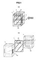
- Fig. 1 includes Fig. 1 (a) as a schematic perspective view of the electric power conversion system according to the present embodiment, and Fig. 1 (b) as a schematic exploded view thereof.
- Fig. 1 (a) is the perspective view of the system when installed, and the system is made up by connecting a body cover 3 (cover) at the front of the system with a body case 2 (casing) on the back side thereof.
- Fig. 1 (b) is the exploded view of the system, in which the cover 3 covers a main circuit board 7 to be connected with the casing 2. As shown in Fig.
- the cover 3 is provided with vent hole slits A2 (air-intakes) formed on both side faces thereof, the main circuit board 7 is provided with notched through-holes 22 (first air-flow holes) formed in an upper part thereof, and the casing 2 is provided with notched vent holes A3 (second air-flow holes) formed on a front face thereof.
- Cooling fins 1 are provided inside the casing 2, and a power semiconductor 11 (not shown) is installed in the fins, thereby enabling the fins to play a role in releasing heat of the power semiconductor 11.
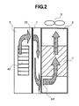
- Fig. 2 is a side view of the electric power conversion system as seen from a direction indicated by an arrow shown in Fig. 1 (a) .
- Air flow inside the system according to the present embodiment is described hereinafter.
- Cooling fans 6 fans
- arrows shown in Fig. 2 indicate the air flow inside the electric power conversion system according to the present embodiment.
- the cooling fans 6 provided in the upper part of the casing 2 are intended to execute the operation for sucking out air, and air from outside, entering the air-intakes A2 (air present in space between the cover 3, and the main circuit board 7), passes through the first air-flow holes 22 of the main circuit board 7 to subsequently pass through space between the main circuit board 7, and the casing 2 before passing through the second air-flow holes A3 to be sucked out to the outside of the system by the cooling fans 6. Positional relationship between those air-flow holes, and the air-intakes, and operational function of the air flow will be described in detail later on.
- Fig. 3 is a detailed exploded perspective view of the electric power conversion system according to the present embodiment.
- Fig. 1 is the perspective view of the electric power conversion system when it is installed, however,
- Fig. 3 is a view of the electric power conversion system during a manufacturing process, showing the perspective view of the system when horizontally oriented. That is, the cover 3 disposed at the front in Fig. 1 is seen as disposed on the upper side in Fig. 3 , and the casing 2 disposed on the back side is seen as disposed on the lower side in Fig. 3 .
- a detailed layout inside the electric power conversion system is described hereinafter with reference to Fig. 3 .
- reference numeral 1 denotes the cooling fins
- 2 the body case (casing), 3 the body cover (cover), 4 a leader plate, 5 a cooling-fan-mounting plate, and 6 the cooling fans (fans), respectively.
- reference numeral 7 denotes the main circuit board including a driver circuit, a power supply circuit, and so forth, 8 a substrate on which main circuit electrolytic capacitors CB are mounted, 9 a control circuit, and 10 a conductor copper bar, respectively.
- a composite module 11 power semiconductor module as a power element is mounted in the cooling fins (fins) 1.
- a control terminal block TM 1 is attached to the cover 3 with two screws as shown by attachment lines C1, C2, respectively. Further, the main circuit board 7 is attached to the cover 3 with three screws as shown by attachment lines C4 to C6, respectively.
- the casing 2 is provided with ten holes A1 for enabling the electrolytic capacitors CB to penetrate therethrough, respectively, such that the substrate 8 for the electrolytic capacitors CB can be attached to the casing 2 with two screws as shown by attachment lines C7, C8, respectively.
- the cooling fans 6, each being a component having a limited life-time, are designed in structure such that the cooling fans 6 are housed in the cooling-fan-mounting plate 5, and the cooling-fan-mounting plate 5 is fitted in the casing 2 without using screws in order to enable the cooling fans 6 to be freely removable.
- the electric power conversion system is made up such that the casing is provided with the composite module, the main circuit board is disposed so as to overlie the front face of the casing, and further, the cover (body cover 3) is disposed in such a way as to cover up the main circuit board.
- the casing is formed integrally with the cover by connecting the casing with the cover, thereby forming the electric power conversion system.
- the electrolytic capacitors CB (ten lengths) most vulnerable to rise in temperature are disposed so as to be arranged in a lower part of the electric power conversion system.
- the lower part of the electric power conversion system refers to the lower part of the electric power conversion system in a state in which the electric power conversion system of a wall-hung type is installed on the wall.
- Fig. 1 is a view showing the state in which the electric power conversion system is installed.
- Fig. 5 there is shown the system as-assembled, however, when the system is actually installed, the system is set upright from this state to be subsequently installed.
- the electrolytic capacitors CB are installed on the most upstream side in the direction of cooling air distribution by the cooling fans 6, that is, the lower part of the system.
- An inverter that is an electric power conversion system is generally of a wall-hung type in structure, vertically attached to a steel plate such as a panel, and so forth, and the inverter is required to be small in size, and to be rendered compact. Then, for the inverter, use is made of, for example, a die-cast case with cooling fins formed on an inner surface of a box-like member having the sidewall, and with power semiconductors, and circuit devices such as a control circuit, and so forth, mounted on the die-cast case, rise in the internal temperature of the electric power conversion system is checked by applying forced air-cooling to the die-cast case, thereby aiming at miniaturization of the system.
- vent hole slits A4 for sucking in air from outside are provided in a lower part of the casing.
- the system is structured such that the vent hole slits A4 are provided not only on the underside of the system but also in a lower part at respective sides of the system. The air sucked in from outside through the vent hole slits A4 is first delivered to the electrolytic capacitors, thereby enabling the electrolytic capacitors to be sufficiently cooled.
- an electrolytic capacitor is very susceptible to the effect of rise in temperature, and a lifetime thereof undergoes extreme reduction as known by Arrhenius' law (the law of 10°C half-life).
- the electrolytic capacitors CB are disposed on the lower side of the composite module 11, which is the a main heat generation source, and on the inflow side (the upstream side) of a cool wind, so that it is possible to satisfactorily check deterioration of the electrolytic capacitors CB, due to rise in temperature, caused by the heat generation source.
- the lifetime of consumable articles such as the electrolytic capacitors can be prolonged, it is possible to enhance reliability of the electric power conversion system while attaining reduction in cost.
- the reason why the ten lengths of the electrolytic capacitors are used instead of one length thereof in the case of the present embodiment is given as follows. That is because the present embodiment has a feature in that sharing of the substrate 8 for the electrolytic capacitors, and the casing 2 is intended such that even if capacity and an input voltage of the electric power conversion system vary, this can be coped with the same substrate for the electrolytic capacitors, and the same casing 2.
- Fig. 4 is a schematic illustration showing a state in which circuit components are attached to the cooling fins 1 (fins).
- the cooling fins are intended to achieve heat release against heat of the composite module through heat exchange, as described in the foregoing.
- the cooling fins 1 are attached to the casing 2 with eight screws, as shown by attachment lines C13 to C20, respectively.
- the composite module 11 is attached to the cooling fins 1 with four screws, as shown by attachment lines C9 to C12, respectively.
- the notched vent holes A3 oriented in a direction substantially orthogonal to the direction of a cooling air flow (the horizontal direction when the electric power conversion system is installed) are provided in a lower part of the front face of the casing 2, that is, on the upstream side of the cooling air from the vent hole slits A4.
- the casing instead of providing shielding in order to prevent heat of the power semiconductor module from being transferred to the main circuit board having the driver circuit, the casing is provided with the notched vent holes A3, thereby causing heat generated at the main circuit board to be circulated. That is, it is possible to cause air from the main circuit board to flow toward the cooling fans through the intermediary of the notched vent holes by an operation of the fans, for sucking out air inside the casing.
- the notched vent hole A3 is provided at two spots, however, there is no limitation to the number of the notched vent holes A3, and an area of each of the notched vent holes A3. Further, with the present embodiment, the notched vent holes A3 are positioned on the lower side of the cooling fins, and the fans are provided in the upper part of the casing, thereby causing the air from the main circuit board to flow toward the cooling fans through the intermediary of the notched vent holes by the operation of the fans, for sucking out the air inside the casing.
- Fig. 5 is a view showing an external appearance of the electric power conversion system according to the present embodiment.
- a surface cover 14, and a terminal block cover 15 are attached to the cover 3 with two screws, respectively, as shown by attachment lines C21, C22, and C23, C24, respectively.
- the surface cover 14 is structured such that a digital control panel 17 is to be attached thereto after a blind cover 16 is attached thereto.
- Fig. 6 is a view showing a layout of principal components of the main circuit board 7.
- a cable 18 is for use as an interface with the control circuit 9.
- a switching transformer 19, and a switching element 21 make up a MOS - FET as the fundamental component of a DC / DC converter.
- a cable 20 is a cable used for power supply to the cooling fans 6.
- Fig. 7 is a schematic view broadly showing the main circuit board of the electric power conversion system according to the present embodiment.
- a plurality of the notched through-holes 22 are provided in the main circuit board. Since the main circuit board 7 is provided with the notched through-holes 22, air present between the main circuit board 7, and the cover 3 covering the main circuit board 7 is caused to flow to the front face of the casing through the notched through-holes 22. This flow of the air is caused by the operation of the cooling fans 6 shown in Figs. 2 and 3 , respectively.
- the main circuit board 7 is not thermally shielded from the composite module, however, since the main circuit board 7 is provided with the notched through-holes 22, and the casing is provided with the notched vent holes A3, the air from the main circuit board 7 as well can be circulated by the operation of the cooling fans 6, for sucking out air, to thereby cause the air inside the casing to flow to the fins 1.
- vent hole slits A2 are provided on both the side faces of the cover 3 as shown in Figs. 1 and 3 , respectively.
- the vent hole slits A2 are provided on both the side faces of the cover 3 as shown in Figs. 1 and 3 , respectively.
- the vent hole slits A2 open on both the side faces of the cover 3, and the notched through-holes 22 in a state in which the main circuit board 7 is normally attached to the casing 2 so as to be mounted thereon, and the cooling-fan-mounting plate 5 is fitted to the casing 2.
- a line D1 - D2 in Fig. 3 indicates the uppermost part line of the vent hole slits A2. That is, D1 - D2 is a line indicating the most downstream side of the vent hole slits A2, in the direction of the cooling air flow, corresponding to the longitudinal direction of the casing 2. And the notched through-holes 22 are provided in parts of the main circuit board, corresponding to a region between the line D1 - D2, and the cooling-fan-mounting plate 5. That is, the uppermost part line D3 - D4 of the vent hole slits A2 open on both the side faces of the cover 3, shown in Fig. 3 , in the direction orthogonal to the vent hole slits A2, corresponds to a projection line D3 - D4 on the main circuit board 7, as shown in Fig. 7 .
- the region between the uppermost part line D1 - D2 of the vent hole slits A2, and the cooling-fan-mounting plate 5 corresponds to a region of the main circuit board 7, indicated by an arrow line E in Fig. 6 .
- the reason why the plurality of the notched through-holes 22 are designed to be disposed in the parts of the main circuit board 7, corresponding to the region (the region indicated by the arrow line E) between D1 - D2, and the cooling-fan-mounting plate 5, is given as follows.
- the notched through-holes 22 are provided on the parts of the main circuit board 7, corresponding to the region indicated by the arrow line E shown in Fig. 6 , and this region corresponds to a region in the casing, on the downstream side of the cooling air from the vent hole slits A4, corresponding to the upper part of the electric power conversion system.
- the electric power conversion system according to the present embodiment is of the wall-hung type in structure, so that the cooling fans 6 are installed in the upper part of electric power conversion system when the system is installed.
- the notched through-holes 22 are disposed in the vicinity of components relatively large in loss generated by themselves among components mounted on the main circuit board.
- the components relatively large in loss generated by themselves among the components mounted on the main circuit board include the switching transformer 19, and the switching element 21, making up the MOS - FET serving as the DC / DC converter, resistors (not shown), and so forth.
- the notched through-holes 22 of the main circuit board 7 are provided on the upper side of the vent hole slits A2, and the notched vent holes A3 of the casing are provided on the lower side of the notched through-holes 22, and on the lower side of the cooling fans.
- air from the air-intakes flows over the upper part of the main circuit board, and subsequently, flows toward the notched vent holes A3 of the casing via the notched through-holes 22.
- the air is sucked out to outside by the fans 6 after passing through the cooling fins 1 via the notched vent holes A3.
- it is possible to enhance circulation efficiency of the air inside the system by virtue of positional relationship among those air-flow holes and air-intakes.
- the air from the vent hole slits A2 flows to a first space between the main circuit board, and the cover, continuing to flow to a second space between the main circuit board, and the front face of the casing. Then, the air from the second space flows to the interior of the casing, and is subsequently sucked out to the outside of the electric power conversion system by the fans 6.
- the notched through-holes 22 (the first air-flow holes) whereby the first space communicates with the second space at this point in time are disposed so as to be positioned on the upper side of the vent hole slits A2 (the air-intakes).
- the second air-flow holes whereby the second space communicates with the interior of the casing are disposed so as to be positioned on the lower side of the first air-flow holes, and on the lower side of the cooling fins covered by the casing.
- the fans provided in the upper part of the casing to suck out the air inside the casing, the air from the second air-flow holes is subjected to heat exchange at the cooling fins to be subsequently discharged to the outside of the electric power conversion system.
- the fans are operated so as to cause the air from the second air-flow holes to flow to the cooling fins, and placement of the fans is not limited to the upper part of the casing.
- Fig. 8 is a schematic illustration showing an example of a simulation on flow rate distribution inside the casing with one embodiment of an electric power conversion system according to the invention.
- Fig. 8 (a) shows an example of a simulation on flow rate distribution inside an inverter, wherein the notched vent holes A3 of the casing 2 are provided on the downstream side of a cooling air so as to be oriented in the direction substantially orthogonal to the flow direction of the cooling air, and the notched through-holes 22 are not provided in the main circuit board.
- Fig. 8 (b) shows an example of a simulation on flow rate distribution inside an inverter according to the embodiment of the invention, wherein the notched vent holes A3 (the second air-flow holes) of the casing 2 are provided on the upstream side of the cooling air (in the lower part of the system), and are oriented in the direction substantially orthogonal to the direction of the cooling air flow, and the notched through-holes 22 (the first air-flow holes) are provided in the main circuit board.
- the flow rate distribution inside the inverter shows uniform air flows all around, thereby proving that heat stagnation does not occur.
- the components relatively large in losses generated by themselves are disposed in the region indicated by the arrow line E in Fig. 6 , and the notched through-holes (the first air-flow holes) are disposed in the vicinity of those components, thereby causing air surrounding those components to be circulated within the system.
- occurrence of heat stagnation can be checked as shown in the simulation of Fig. 8 (b) , so that it becomes possible to enhance cooling performance while attaining the miniaturization of the electric power conversion system.
- an electric power conversion system capable of supplying a variable voltage AC power at variable frequency to an AC motor, wherein even if the mount density of the elements on the circuit board is enhanced, the operation of the cooling fans (fans), for cooling air, can be sufficiently obtained, and the miniaturization of the system is satisfactorily attained without being accompanied by the risk of rise in temperature.
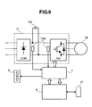
- Fig. 9 is a block diagram of the main circuit of the electric power conversion system.
- the inverter according to the present embodiment is provided with a power conversion circuit including a forward-direction converter CON for converting AC power into DC power, a smoothing capacitor CB, and a reverse-direction converter INV for converting DC power into AC power at an optional frequency, and is capable of driving an AC motor IM at a desired frequency.
- the cooling fans 6 are installed at a position where the power modules contained in the forward-direction converter CON, and the reverse-direction converter INV, respectively, can be cooled.
- control panel 17 is provided with a display screen capable of showing an abnormal display, and if abnormality of the electric power conversion system is detected, this will be shown on the display screen.
- the control panel 17 is made up so as to enable a user to operate the same while looking at display on the display screen by taking operability of the user of the same as a digital control panel into consideration.
- the display screen need not necessarily be made up integrally with the control panel 17, but the display screen is preferably made up integrally with the control panel 17 such that an operator of the control panel 17 can operate while looking at display on the display screen.
- the various control data blocks for the electric power conversion system, inputted from the control panel 17, are stored in a memory (not shown).
- Temperature detectors THM each detect the temperature of each of the power modules incorporated in the forward-direction converter CON, and the reverse-direction converter INV, respectively.
- the temperature detector THM use may be made of either a temperature relay with an output contact being turned ON / OFF at a predetermined temperature, or a thermistor with a resistance value variable according to temperature.
- a thermistor characterized in that a resistance value increases with a rise in temperature or a thermistor characterized in that the resistance value decreases with the rise in temperature.
- control circuit 9 takes charge of controlling the inverter in whole.
- the control circuit 9 executes control processing necessary for the system in whole besides controlling the switching element of the reverse-direction converter INV on the basis of the various control data blocks inputted from the control panel 17.
- a microcomputer control processor
- control processor for executing operation on the basis of information from stored data of the memory where the various control data blocks are stored, but description of an internal configuration thereof is omitted.
- the driver circuit drives the switching element of the reverse-direction converter INV on the basis of a command from the control circuit 9. Further, a switching regulator circuit (DC / DC converter) is mounted on the driver circuit, generating various DC voltages necessary for operation of the electric power conversion system to be supplied to respective constituent elements.
- a switching regulator circuit DC / DC converter
Landscapes
- Engineering & Computer Science (AREA)
- Microelectronics & Electronic Packaging (AREA)
- Power Engineering (AREA)
- Physics & Mathematics (AREA)
- Thermal Sciences (AREA)
- Inverter Devices (AREA)
- Cooling Or The Like Of Electrical Apparatus (AREA)
Applications Claiming Priority (1)
| Application Number | Priority Date | Filing Date | Title |
|---|---|---|---|
| JP2007196892A JP5011016B2 (ja) | 2007-07-30 | 2007-07-30 | 電力変換装置 |
Publications (3)
| Publication Number | Publication Date |
|---|---|
| EP2020739A2 true EP2020739A2 (fr) | 2009-02-04 |
| EP2020739A3 EP2020739A3 (fr) | 2015-08-05 |
| EP2020739B1 EP2020739B1 (fr) | 2017-08-23 |
Family
ID=40091609
Family Applications (1)
| Application Number | Title | Priority Date | Filing Date |
|---|---|---|---|
| EP08011421.8A Ceased EP2020739B1 (fr) | 2007-07-30 | 2008-06-24 | Système de conversion de puissance électrique |
Country Status (6)
| Country | Link |
|---|---|
| US (1) | US8159820B2 (fr) |
| EP (1) | EP2020739B1 (fr) |
| JP (1) | JP5011016B2 (fr) |
| KR (1) | KR100997012B1 (fr) |
| CN (1) | CN101359866B (fr) |
| TW (1) | TWI381797B (fr) |
Cited By (3)
| Publication number | Priority date | Publication date | Assignee | Title |
|---|---|---|---|---|
| GB2512409A (en) * | 2013-03-28 | 2014-10-01 | Control Tech Ltd | Devices and methods for cooling components on a PCB |
| WO2015029276A1 (fr) | 2013-08-30 | 2015-03-05 | Kabushiki Kaisha Toshiba | Dispositif de conversion d'énergie électrique pour véhicule et véhicule ferroviaire |
| US9398682B2 (en) | 2013-03-28 | 2016-07-19 | Control Techniques Limited | Devices and methods for cooling components on a PCB |
Families Citing this family (44)
| Publication number | Priority date | Publication date | Assignee | Title |
|---|---|---|---|---|
| US11452242B2 (en) | 2007-06-14 | 2022-09-20 | Switch, Ltd. | Air handling unit with a canopy thereover for use with a data center and method of using the same |
| US9823715B1 (en) | 2007-06-14 | 2017-11-21 | Switch, Ltd. | Data center air handling unit including uninterruptable cooling fan with weighted rotor and method of using the same |
| US9693486B1 (en) | 2007-06-14 | 2017-06-27 | Switch, Ltd. | Air handling unit with a canopy thereover for use with a data center and method of using the same |
| US9788455B1 (en) | 2007-06-14 | 2017-10-10 | Switch, Ltd. | Electronic equipment data center or co-location facility designs and methods of making and using the same |
| US8523643B1 (en) | 2007-06-14 | 2013-09-03 | Switch Communications Group LLC | Electronic equipment data center or co-location facility designs and methods of making and using the same |
| US20090211773A1 (en) * | 2008-05-02 | 2009-08-27 | Gooch Rodger J | Fire suppression system and associated methods |
| FI20085945A7 (fi) * | 2008-10-08 | 2010-04-09 | Abb Oy | Elektroniikkalaitteen jäähdytysrakenne ja menetelmä |
| JP5418847B2 (ja) * | 2009-08-04 | 2014-02-19 | 株式会社安川電機 | 電力変換装置 |
| CN102042247B (zh) * | 2009-10-20 | 2014-10-22 | 建准电机工业股份有限公司 | 风扇组的运转控制电路 |
| US8289709B2 (en) * | 2009-11-11 | 2012-10-16 | Nextronex Inc. | Inverter system |
| JP2011187762A (ja) * | 2010-03-10 | 2011-09-22 | Fujitsu Ltd | 冷却装置、電子装置 |
| TWI457749B (zh) * | 2010-06-21 | 2014-10-21 | Acbel Polytech Inc | High power density power supplies for miniaturized servers |
| KR101156903B1 (ko) * | 2010-10-28 | 2012-06-21 | 삼성전기주식회사 | 전력변환모듈의 방열장치 |
| JP2012244657A (ja) * | 2011-05-16 | 2012-12-10 | Toshiba Schneider Inverter Corp | 冷却ファンの取付構造および取付方法 |
| CN102158059A (zh) * | 2011-05-19 | 2011-08-17 | 台安科技(无锡)有限公司 | 一种大功率小型化变频器 |
| JP5827513B2 (ja) * | 2011-07-25 | 2015-12-02 | 株式会社アイ・ライティング・システム | スイッチング電源装置 |
| CN102510704B (zh) * | 2011-10-27 | 2014-09-03 | 华为技术有限公司 | 盒式机箱通讯设备的散热系统、盒式机箱及通讯设备 |
| JP5965779B2 (ja) | 2012-08-24 | 2016-08-10 | 株式会社日立産機システム | 電力変換装置 |
| JP5657716B2 (ja) * | 2013-01-15 | 2015-01-21 | ファナック株式会社 | 放熱器を備えたモータ駆動装置 |
| DE112014001321T5 (de) * | 2013-03-14 | 2016-01-14 | Yazaki Corporation | Elektronikkomponenten-Anordnungsaufbau und elektrischer Anschlusskasten |
| US9198331B2 (en) | 2013-03-15 | 2015-11-24 | Switch, Ltd. | Data center facility design configuration |
| JP6225477B2 (ja) * | 2013-05-16 | 2017-11-08 | 富士通株式会社 | 電子機器 |
| FR3018013B1 (fr) * | 2014-02-26 | 2018-01-12 | Valeo Equipements Electriques Moteur | Ensemble electronique pour machine electrique tournante pour vehicule automobile |
| JP6337547B2 (ja) * | 2014-03-20 | 2018-06-06 | 富士通株式会社 | 電子機器筐体 |
| CN104600960B (zh) * | 2014-04-17 | 2017-02-15 | 南车株洲电力机车研究所有限公司 | 紧凑型电源柜主单元柜及其组装方法及柜内组件排布方法 |
| JP5972508B1 (ja) * | 2015-02-23 | 2016-08-17 | 三菱電機株式会社 | 半導体電力変換器 |
| US9412671B1 (en) * | 2015-04-30 | 2016-08-09 | Taiwan Semiconductor Manufacturing Co., Ltd. | Method for controlling processing temperature in semiconductor fabrication |
| JP6156470B2 (ja) * | 2015-11-20 | 2017-07-05 | 株式会社安川電機 | 電力変換装置 |
| JP6575914B2 (ja) * | 2016-01-29 | 2019-09-18 | パナソニックIpマネジメント株式会社 | 電力変換装置 |
| US20180077819A1 (en) | 2016-09-14 | 2018-03-15 | Switch, Ltd. | Ventilation and air flow control |
| JP6769798B2 (ja) * | 2016-09-21 | 2020-10-14 | 荏原冷熱システム株式会社 | 熱交換器 |
| JP6998115B2 (ja) * | 2017-02-27 | 2022-01-18 | 川崎重工業株式会社 | ロボットコントローラ |
| WO2018179143A1 (fr) * | 2017-03-29 | 2018-10-04 | 三菱電機株式会社 | Dispositif de commande de propulsion |
| JP7039779B2 (ja) * | 2017-09-22 | 2022-03-23 | ダイヤゼブラ電機株式会社 | 空冷機構付き電子機器 |
| JP2019057656A (ja) * | 2017-09-22 | 2019-04-11 | ダイヤモンド電機株式会社 | 空冷機構付き電子機器 |
| ES2970590T3 (es) * | 2018-02-02 | 2024-05-29 | Toshiba Mitsubishi Electric Industrial Systems Corp | Dispositivo de conversión de energía |
| KR102787083B1 (ko) * | 2019-01-10 | 2025-03-26 | 울프스피드 인코포레이티드 | 전력 장치를 병렬화하기 위한 낮은 인덕턴스와 빠른 스위칭을 갖는 고전력 다층 모듈 |
| WO2020147961A1 (fr) * | 2019-01-18 | 2020-07-23 | Bitzer Electronics A/S | Ensemble de transfert de chaleur et dispositif électronique de puissance |
| KR102299859B1 (ko) | 2019-01-25 | 2021-09-08 | 엘에스일렉트릭 (주) | 인버터 장치 및 이를 포함하는 전력변환장치 |
| KR102141564B1 (ko) | 2019-01-25 | 2020-08-05 | 엘에스일렉트릭(주) | 인버터 장치 및 이를 포함하는 인버터 패널 |
| KR102222270B1 (ko) | 2019-01-25 | 2021-03-04 | 엘에스일렉트릭(주) | 전력 변환 장치 |
| US10782750B1 (en) * | 2019-04-23 | 2020-09-22 | Quanta Computer Inc. | Remote intake for fan module |
| DE102021201248B4 (de) * | 2021-02-10 | 2025-03-27 | Vitesco Technologies Germany Gmbh | Steuermodul für ein Fahrzeug mit mindestens einem Elektromotor und einem Getriebe |
| JP7854612B2 (ja) | 2023-03-29 | 2026-05-07 | パナソニックIpマネジメント株式会社 | 直流電力を供給する配線器具 |
Family Cites Families (21)
| Publication number | Priority date | Publication date | Assignee | Title |
|---|---|---|---|---|
| US4399484A (en) * | 1981-03-10 | 1983-08-16 | The United States Of America As Represented By The Secretary Of The Air Force | Integral electric module and assembly jet cooling system |
| JPH0795771A (ja) * | 1993-09-20 | 1995-04-07 | Sansha Electric Mfg Co Ltd | 電源装置の冷却構造 |
| JP3348552B2 (ja) * | 1994-12-28 | 2002-11-20 | 富士電機株式会社 | 電子機器の冷却装置 |
| US5905647A (en) * | 1997-01-20 | 1999-05-18 | Kabushiki Kaisha Toshiba | Inverter with incorporated filter circuit and improved component cooling arrangement |
| JP2812323B2 (ja) | 1997-03-21 | 1998-10-22 | 株式会社日立製作所 | インバータ装置 |
| JPH1169774A (ja) * | 1997-08-19 | 1999-03-09 | Hitachi Ltd | 電力変換装置 |
| JP3994235B2 (ja) * | 1997-09-19 | 2007-10-17 | 株式会社安川電機 | 制御装置の冷却構造 |
| JP2000022373A (ja) * | 1998-07-03 | 2000-01-21 | Toshiba Corp | 電子機器 |
| JP2000174474A (ja) * | 1998-12-02 | 2000-06-23 | Nippon Columbia Co Ltd | 電子機器の冷却装置 |
| US6081423A (en) * | 1998-12-22 | 2000-06-27 | The Esab Group, Inc. | Power supply with obliquely impinging airflow |
| JP2000323878A (ja) * | 1999-05-12 | 2000-11-24 | Matsushita Electric Ind Co Ltd | 電子機器の冷却構造 |
| KR20010056511A (ko) * | 1999-12-15 | 2001-07-04 | 구자홍 | 인버터 히트 펌프용 피씨비 및 컴프레서의 방열 구조 |
| SE0003189D0 (sv) * | 2000-09-08 | 2000-09-08 | Emerson Energy Systems Ab | A spring device for pressing an electronic component towards a heat sink body |
| US6538885B1 (en) * | 2000-09-15 | 2003-03-25 | Lucent Technologies Inc. | Electronic circuit cooling with impingement plate |
| JP4024099B2 (ja) * | 2002-07-23 | 2007-12-19 | 三洋電機株式会社 | 系統連系発電装置 |
| JP4639648B2 (ja) * | 2004-06-03 | 2011-02-23 | 富士電機システムズ株式会社 | インバータ装置 |
| US7286348B2 (en) * | 2004-11-16 | 2007-10-23 | Hewlett-Packard Development Company, L.P. | Housing assembly for a computer |
| TW200622566A (en) * | 2004-11-18 | 2006-07-01 | Ind Origami Llc | A heat dissipation assembly and method for cooling heat-generating components in an electrical device |
| US7218517B2 (en) * | 2004-12-07 | 2007-05-15 | International Business Machines Corporation | Cooling apparatus for vertically stacked printed circuit boards |
| DE202006008792U1 (de) * | 2006-06-01 | 2007-10-04 | Diehl Ako Stiftung & Co. Kg | Solarwechselrichter |
| US7929301B2 (en) * | 2008-11-03 | 2011-04-19 | Microsoft Corporation | Splash resistant power adapter |
-
2007
- 2007-07-30 JP JP2007196892A patent/JP5011016B2/ja active Active
-
2008
- 2008-05-30 TW TW097120210A patent/TWI381797B/zh active
- 2008-06-24 EP EP08011421.8A patent/EP2020739B1/fr not_active Ceased
- 2008-06-25 CN CN2008101250028A patent/CN101359866B/zh not_active Expired - Fee Related
- 2008-06-26 US US12/215,491 patent/US8159820B2/en active Active
- 2008-06-26 KR KR1020080060543A patent/KR100997012B1/ko active Active
Cited By (6)
| Publication number | Priority date | Publication date | Assignee | Title |
|---|---|---|---|---|
| GB2512409A (en) * | 2013-03-28 | 2014-10-01 | Control Tech Ltd | Devices and methods for cooling components on a PCB |
| GB2512409B (en) * | 2013-03-28 | 2015-08-26 | Control Tech Ltd | Devices and methods for cooling components on a PCB |
| US9398682B2 (en) | 2013-03-28 | 2016-07-19 | Control Techniques Limited | Devices and methods for cooling components on a PCB |
| WO2015029276A1 (fr) | 2013-08-30 | 2015-03-05 | Kabushiki Kaisha Toshiba | Dispositif de conversion d'énergie électrique pour véhicule et véhicule ferroviaire |
| CN105408183A (zh) * | 2013-08-30 | 2016-03-16 | 株式会社东芝 | 用于车辆的电力变换装置以及铁路车辆 |
| EP3039780A4 (fr) * | 2013-08-30 | 2017-04-12 | Kabushiki Kaisha Toshiba | Dispositif de conversion d'énergie électrique pour véhicule et véhicule ferroviaire |
Also Published As
| Publication number | Publication date |
|---|---|
| EP2020739B1 (fr) | 2017-08-23 |
| CN101359866B (zh) | 2012-03-28 |
| JP2009033910A (ja) | 2009-02-12 |
| KR20090013023A (ko) | 2009-02-04 |
| TW200913865A (en) | 2009-03-16 |
| US8159820B2 (en) | 2012-04-17 |
| US20090034309A1 (en) | 2009-02-05 |
| JP5011016B2 (ja) | 2012-08-29 |
| TWI381797B (zh) | 2013-01-01 |
| EP2020739A3 (fr) | 2015-08-05 |
| CN101359866A (zh) | 2009-02-04 |
| KR100997012B1 (ko) | 2010-11-25 |
Similar Documents
| Publication | Publication Date | Title |
|---|---|---|
| EP2020739B1 (fr) | Système de conversion de puissance électrique | |
| EP2603068B1 (fr) | Dispositif et procédé utilisant une induction pour améliorer le refroidissement par convection naturelle | |
| JP5980537B2 (ja) | 最適な構造を備えた可変速駆動装置 | |
| JP4700471B2 (ja) | 情報処理装置、及びその製造方法 | |
| CN102573412A (zh) | 带冷却功能的控制装置 | |
| JP5469838B2 (ja) | 並べて配置される複数台の電力変換装置およびその設置方法 | |
| JP4498367B2 (ja) | 電源盤 | |
| JP5309243B2 (ja) | 電力変換装置 | |
| CN112996341A (zh) | 散热组件及电子设备 | |
| JP2018113402A (ja) | 電子装置 | |
| JP5879914B2 (ja) | 車両用の電池モジュール | |
| TWI487474B (zh) | 電子裝置 | |
| JP4605813B2 (ja) | 操作ハウジング | |
| WO2006025689A1 (fr) | Dispositif de refroidissement pour ordinateur utilisant un element thermoelectrique, un ensemble de refroidissement a air et une conduite | |
| US20240230141A1 (en) | Air Conditioner Indoor Unit | |
| US11026353B2 (en) | Arrangement having a housing and a power electronics circuit arranged on a housing base in the housing | |
| JP5703343B2 (ja) | 電力変換装置 | |
| US20230023737A1 (en) | Power Converter | |
| JP2022091293A (ja) | 冷却システム、電力変換装置及び蓄電システム | |
| CN114986346A (zh) | 一种控制系统和电动工具 | |
| US7518869B2 (en) | Information processing apparatus with a chassis for thermal efficiency and method for making the same | |
| CN220492873U (zh) | 一种逆变器壳体盖板结构 | |
| CN120091534A (zh) | 一种电源供应单元以及服务器 | |
| JP2007335624A (ja) | 電子機器用の液冷装置 | |
| WO2024113116A1 (fr) | Dispositif de cuisson, appareil de dissipation de chaleur et système de commande de dissipation de chaleur |
Legal Events
| Date | Code | Title | Description |
|---|---|---|---|
| PUAI | Public reference made under article 153(3) epc to a published international application that has entered the european phase |
Free format text: ORIGINAL CODE: 0009012 |
|
| AK | Designated contracting states |
Kind code of ref document: A2 Designated state(s): AT BE BG CH CY CZ DE DK EE ES FI FR GB GR HR HU IE IS IT LI LT LU LV MC MT NL NO PL PT RO SE SI SK TR |
|
| AX | Request for extension of the european patent |
Extension state: AL BA MK RS |
|
| 17P | Request for examination filed |
Effective date: 20100331 |
|
| PUAL | Search report despatched |
Free format text: ORIGINAL CODE: 0009013 |
|
| AK | Designated contracting states |
Kind code of ref document: A3 Designated state(s): AT BE BG CH CY CZ DE DK EE ES FI FR GB GR HR HU IE IS IT LI LT LU LV MC MT NL NO PL PT RO SE SI SK TR |
|
| AX | Request for extension of the european patent |
Extension state: AL BA MK RS |
|
| RIC1 | Information provided on ipc code assigned before grant |
Ipc: H05K 7/20 20060101ALI20150630BHEP Ipc: H02M 7/00 20060101AFI20150630BHEP Ipc: H01L 25/16 20060101ALI20150630BHEP |
|
| AKX | Designation fees paid |
Designated state(s): DE FR IT |
|
| AXX | Extension fees paid |
Extension state: MK Extension state: BA Extension state: AL Extension state: RS |
|
| GRAP | Despatch of communication of intention to grant a patent |
Free format text: ORIGINAL CODE: EPIDOSNIGR1 |
|
| STAA | Information on the status of an ep patent application or granted ep patent |
Free format text: STATUS: GRANT OF PATENT IS INTENDED |
|
| INTG | Intention to grant announced |
Effective date: 20170313 |
|
| GRAS | Grant fee paid |
Free format text: ORIGINAL CODE: EPIDOSNIGR3 |
|
| GRAA | (expected) grant |
Free format text: ORIGINAL CODE: 0009210 |
|
| STAA | Information on the status of an ep patent application or granted ep patent |
Free format text: STATUS: THE PATENT HAS BEEN GRANTED |
|
| AK | Designated contracting states |
Kind code of ref document: B1 Designated state(s): DE FR IT |
|
| REG | Reference to a national code |
Ref country code: DE Ref legal event code: R096 Ref document number: 602008051712 Country of ref document: DE |
|
| REG | Reference to a national code |
Ref country code: DE Ref legal event code: R097 Ref document number: 602008051712 Country of ref document: DE |
|
| REG | Reference to a national code |
Ref country code: FR Ref legal event code: PLFP Year of fee payment: 11 |
|
| PLBE | No opposition filed within time limit |
Free format text: ORIGINAL CODE: 0009261 |
|
| STAA | Information on the status of an ep patent application or granted ep patent |
Free format text: STATUS: NO OPPOSITION FILED WITHIN TIME LIMIT |
|
| 26N | No opposition filed |
Effective date: 20180524 |
|
| PGFP | Annual fee paid to national office [announced via postgrant information from national office to epo] |
Ref country code: IT Payment date: 20230510 Year of fee payment: 16 Ref country code: FR Payment date: 20230510 Year of fee payment: 16 Ref country code: DE Payment date: 20230502 Year of fee payment: 16 |
|
| REG | Reference to a national code |
Ref country code: DE Ref legal event code: R119 Ref document number: 602008051712 Country of ref document: DE |
|
| PG25 | Lapsed in a contracting state [announced via postgrant information from national office to epo] |
Ref country code: DE Free format text: LAPSE BECAUSE OF NON-PAYMENT OF DUE FEES Effective date: 20250101 |
|
| PG25 | Lapsed in a contracting state [announced via postgrant information from national office to epo] |
Ref country code: FR Free format text: LAPSE BECAUSE OF NON-PAYMENT OF DUE FEES Effective date: 20240630 |
|
| PG25 | Lapsed in a contracting state [announced via postgrant information from national office to epo] |
Ref country code: IT Free format text: LAPSE BECAUSE OF NON-PAYMENT OF DUE FEES Effective date: 20240624 |