EP2020841B1 - Tete de tuloteuse de moissonneuse-batteuse ayant une barre de coupe flexible - Google Patents
Tete de tuloteuse de moissonneuse-batteuse ayant une barre de coupe flexible Download PDFInfo
- Publication number
- EP2020841B1 EP2020841B1 EP07756629.7A EP07756629A EP2020841B1 EP 2020841 B1 EP2020841 B1 EP 2020841B1 EP 07756629 A EP07756629 A EP 07756629A EP 2020841 B1 EP2020841 B1 EP 2020841B1
- Authority
- EP
- European Patent Office
- Prior art keywords
- header
- draper
- assembly
- cutterbar
- frame
- Prior art date
- Legal status (The legal status is an assumption and is not a legal conclusion. Google has not performed a legal analysis and makes no representation as to the accuracy of the status listed.)
- Active
Links
Images







Classifications
-
- A—HUMAN NECESSITIES
- A01—AGRICULTURE; FORESTRY; ANIMAL HUSBANDRY; HUNTING; TRAPPING; FISHING
- A01D—HARVESTING; MOWING
- A01D43/00—Mowers combined with apparatus performing additional operations while mowing
- A01D43/06—Mowers combined with apparatus performing additional operations while mowing with means for collecting, gathering or loading mown material
-
- A—HUMAN NECESSITIES
- A01—AGRICULTURE; FORESTRY; ANIMAL HUSBANDRY; HUNTING; TRAPPING; FISHING
- A01D—HARVESTING; MOWING
- A01D41/00—Combines, i.e. harvesters or mowers combined with threshing devices
- A01D41/12—Details of combines
- A01D41/14—Mowing tables
-
- A—HUMAN NECESSITIES
- A01—AGRICULTURE; FORESTRY; ANIMAL HUSBANDRY; HUNTING; TRAPPING; FISHING
- A01D—HARVESTING; MOWING
- A01D43/00—Mowers combined with apparatus performing additional operations while mowing
-
- A—HUMAN NECESSITIES
- A01—AGRICULTURE; FORESTRY; ANIMAL HUSBANDRY; HUNTING; TRAPPING; FISHING
- A01D—HARVESTING; MOWING
- A01D57/00—Delivering mechanisms for harvesters or mowers
- A01D57/20—Delivering mechanisms for harvesters or mowers with conveyor belts
Definitions
- This invention relates to harvesting equipment and, more particularly, to a draper header adapted for attachment to a combine harvester wherein the header is provided with a flexible cutterbar.
- US patent application publication US-2003/0074876 discloses a multi-section header having a frame that is divided into a central frame portion and two separate wing frame portions each arranged for pivotal movement relative to the central portion about a pivot axis extending in a plane parallel to the forward direction and intersecting a cutterbar so that, as the wing frame portions pivot, the cutterbar flexes in the area adjacent the respective pivot axis.
- a harvesting header comprising an elongated header frame and a cutterbar assembly mounted thereto and extending transversely to the normal direction of travel of the header, the cutterbar assembly including an elongated cutterbar and a plurality of ground-engaging skids attached to said cutterbar along the length thereof, and a draper mechanism behind the cutterbar assembly for receiving severed crop materials from the cutterbar assembly and conveying the materials in a lateral direction with respect to the normal direction of travel of the header, said draper mechanism including a left draper assembly and a right draper assembly that are laterally spaced apart to present a centrally disposed opening, said left and right draper assemblies being driven in mutually opposite directions to deliver crop materials centrally to said central opening, further comprising a central conveyor disposed in said central opening for receiving crop materials from the left and right draper assemblies, said central conveyor being operable to deliver crop materials in a rearward direction toward an outlet, characterised in that the cutterbar is able to flex, independently of the header frame, along its
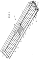
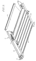
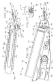
- Figure 1 is a left front isometric view of an embodiment of a draper header having a flexible cutterbar in accordance with the principles of the present invention
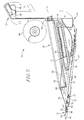
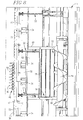
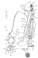
- Fig. 2 is a left side elevational view thereof
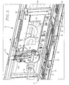
- Fig. 3 is a fragmentary, rear isometric view of the header
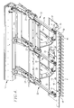
- Fig. 4 is a fragmentary, front isometric view of a portion of the left end of the header illustrating details of construction
- Fig. 5 is a fragmentary fore-and-aft cross-sectional view through the header illustrating the four-bar arm supporting linkage for the cutterbar;
- Fig. 6 is a left end elevational view of the header with drive mechanism and the end panel removed to reveal details of construction
- Fig. 7 is a fore-and-aft cross-sectional view through the central portion of the header showing the center draper thereof;
- Fig. 8 is a fragmentary top plan view of the central portion of the header with structure removed to reveal details of construction
- Fig.9 is a bottom, right front isometric view of the center draper
- FIG. 10 is a left, front isometric view of an alternative embodiment of a draper header having a flexible cutterbar and flexible draper in accordance with the principles of the present invention
- Fig. 11 is a right, rear isometric view thereof
- Fig. 12 is a fragmentary, top plan view of the header of Fig. 10 with portions of the header removed and broken away to reveal details of construction;
- Fig. 13 is a transverse cross-sectional view through the header of Fig. 10 taken substantially along line 13-13 of Fig. 12 with the header in a fully lowered position;
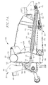
- Fig. 14 is a transverse cross-sectional view through the header of Fig. 10 similar to Fig. 13 but showing the header in a fully raised position;
- Fig. 15 is a fragmentary, bottom isometric view of the right end of the cutterbar assembly showing details of construction
- Fig. 16 is an enlarged, fragmentary, transverse cross-sectional view through the front of the header of Fig. 10 illustrating the relationship between the draper assembly and the cutterbar assembly;
- Fig. 17 is a cross-sectional view through the attachment coupling between the front end of the draper assembly and the proximal ground skid taken substantially along line 17-17 of Fig. 16 ;
- Fig. 18 is a transverse cross-sectional view through the header of Fig. 10 taken along a sight line passing through the central conveyor thereof and showing the header fully lowered;
- Fig. 19 is an enlarged, fragmentary cross-sectional view similar to Fig. 18 with the header fully lowered;
- Fig. 20 is a fragmentary, right front isometric view of the central conveyor of the header of Fig. 10 with portions of the header removed to reveal details of construction;
- Fig. 21 is an enlarged, fragmentary, left rear isometric view of the header of Fig. 10 showing the mounting adaptor frame of the header;
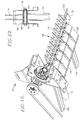
- Fig. 22 is an enlarged, fragmentary cross-sectional view of one of the upright mounting members of the header frame and associated support arms of the header of Fig. 10 .
- Header 10 has a frame at the rear thereof that includes an upper beam assembly 12 extending across the entire width of header 10, and a lower beam assembly 14 that likewise extends across the full width of header 10.
- a number of upright channels 16 interconnect beam assemblies 12, 14 across the backside of header 10 at spaced locations thereacross.
- Upright rear panels 18 on the front sides of channels 16 define an upright rear wall of the header, while a centrally located opening 20 in such panels serves as a crop outlet from header 10 to the feeder housing (not shown) of a combine harvester upon which header 10 may be mounted.
- Header 10 is also provided with left and right end panels 19.
- Lower beam assembly 14 carries a number of arm assemblies 22 that project forwardly from beam assembly 12 at spaced locations along the length thereof.
- Each arm assembly 22 could comprise a single arm or, in another form of the invention as shown, a four-bar linkage having an upper link 24 and a lower link 26 that are respectively connected at their front ends by pivots 28 and 30 to a skid plate 32.
- Links 24, 26 are pivotally connected at their rear ends to support assemblies 23 by rear pivots 25 and 27, respectively ( Fig. 5 ).
- Arm assemblies 22 are biased yieldably upwardly by suitable biasing means, which in the illustrated embodiment comprises a compression spring assembly 29 ( Fig. 5 ).
- skid plate 32 In some instances, such as at the opposite ends of the header 10, only a single one of the arm assemblies 22 is attached to a skid plate 32, while in other portions of the header two or more of the arm assemblies 22 may be attached to a single skid plate 32.
- adjacent ones of the skid plates 32 are hingedly interconnected by a web 34 of flexible material that spans the interface between adjacent skid plates 32 and is secured to such skid plates by suitable fasteners.
- A-frame assemblies 36 ( Fig. 4 ) are provided in association with the two leftmost skid plates 32 to assist in providing structural support for sickle drive mechanism as hereinafter described.
- a continuous, full length, flexible cutterbar 38 constructed of flat plate metal extends across the front of header 10 for its full width.
- Cutterbar 38 is secured to the front extremities of skid plates 32 by mounting lugs 40.
- Carriage bolts 42 at the front ends of lugs 40 attach the same to cutterbar 38, while the rear ends of lugs 40 are secured to skids 32 by suitable fastening means not shown.
- a series of side-by-side sickle guards 44 are bolted to the front edge of cutterbar 38 and project forwardly therefrom along the full length cutterbar 38.
- a representative number of sickle guards 44 are illustrated on the cutterbar 38 in Fig. 1 .
- a reciprocating sickle assembly 46 is carried by guards 44 for severing standing crop materials from the ground as header 10 is advanced.
- Header 10 may be provided with either a single such full-length sickle assembly 46 or with a split sickle assembly comprising two separate sickle assemblies that are driven by two separate mechanisms at opposite ends of header 10.
- sickle assembly 46 may include a generally rectangular in cross section sickle bar 48 on which are secured a number of side-by-side knife sections 50.
- a pair of left and right, center delivery draper assemblies 52 and 54 are located behind cutterbar 38 in disposition for receiving severed crop materials from sickle assembly 46 and moving such materials toward the center of header 10. Drapers 52, 54 are spaced apart near the center of header 10 to define a generally rectangular in plan receiving opening 56 for crop materials from drapers 52, 54.
- Each draper assembly 52, 54 comprises a wide, flat, endless draper belt that is looped around a pair of fore-and-aft rollers at opposite ends of the assembly.
- Fig. 6 illustrates such a draper belt 58 wrapped around an outboard roller 60 at one end of the endless belt 58.
- the other, inboard roller of left draper assembly 52 is not visible in the drawings, but such an inboard roller 62 is visible in Fig.
- header 10 has a full width, generally Z-shaped support channel 68 extending the full width of header 10.
- a feather plate 70 which may be constructed in one or more sections, is attached to the rear edge of cutterbar 38 and extends upwardly and rearwardly therefrom to provide a transition for severed crop materials from sickle assembly 46 to drapers 52 and 54. The rear extremity of feather plate 70 is supported on a forwardly projecting portion of the Z-shaped support member 64 of each draper assembly 52, 54.
- center draper assembly 72 is disposed within receiving opening 56 for taking delivery of severed materials from left and right draper assemblies 52, 54 and feeding the materials upwardly and rearwardly through central opening 20 into the feederhouse of the combine harvester.
- center draper assembly 72 includes a pair of transversely extending rolls 74 and 76 that are spaced apart in a fore-and-aft direction and are wrapped by an endless draper belt 78.
- draper belt 78 is slatted, as are the draper belts 58 of left and right draper assemblies 52, 54.
- a pair of laterally spaced apart, fore-and-aft extending channels 80 support the rolls 74, 76 and are, in turn, supported at their rear ends by lower beam assembly 14 and at their front ends by transverse support channel 68.
- a downwardly and rearwardly inclined ramp plate 82 leads from the rear extremity of feather plate 70 in the region of receiving opening 56 into overlapping relationship with the front extremity of center draper 72 for assisting in guiding materials that have been severed by the central portion of sickle assembly 46 into the center draper assembly 72.
- a center-gathering auger 84 spans receiving opening 56 above the latter and in front of discharge opening 20 at the rear of center draper assembly 72 for consolidating crop materials from draper assemblies 52, 54 and 72 into a relatively low profile mat that can be handled by the conveying mechanism of the feederhouse into which the materials are fed.
- Header 10 is preferably adapted to be attached directly to the front end of the feederhouse of a combine harvester.
- header 10 is mounted upon an adapter which is, in turn, attached to the feederhouse.
- Such an adapter would have its own center draper, as well as overhead auger, in which event the center draper 82 and overhead auger 84 associated with header 10 of the present invention would not be utilized.
- upper beam assembly 12 is provided with downwardly opening mounting pockets 86 that are adapted to matingly receive corresponding upwardly projecting mounting structure on the feederhouse.
- Rests 88 on top beam assembly 12 are disposed rearwardly adjacent pockets 86 for engaging top surface structure on the feederhouse to assist in supporting header 10 on the combine harvester.
- a pair of rearwardly projecting guides 90 ( Fig. 3 ) are disposed adjacent rests 88 and slightly outboard therefrom for the purpose of embracing opposite sides of the feederhouse and aligning central opening 20 with the mouth of the feederhouse.
- Multiple sets of receiving sockets 92 are disposed below central opening 20 in association with lower beam assembly 14 for receiving mounting projections on the feederhouse in an arrangement that depends upon the particular brand of combine harvester to which header 10 is mounted.
- header 10 may be driven in any number of suitable ways. A variety of different mechanical and/or hydraulic drive systems could be utilized.
- a transverse jackshaft 94 ( Fig. 3 ) at the rear of header 10 receives input driving power in an appropriate manner from the combine harvester upon which header 10 is mounted.
- Driving power from jackshaft 94 is brought to the front of the machine by a belt and pulley assembly 96 on left end panel 19, which assembly 96 is operably coupled with a suitable mechanical sickle drive mechanism 98 as illustrated in Fig. 2 .
- Sickle drive mechanism 98 is drivingly coupled with sickle assembly 46.
- draper assemblies 52, 54 and 72, as well as overhead auger 84 may be hydraulically or mechanically driven by suitable drive systems.
- header 10 will ride lightly along the ground with skids 32 engaging the surface of the ground.
- Suitable flotation springs are preferably coupled with the feederhouse in such a way that the combined weight of the feederhouse and header 10 is carried in large measure by such flotation springs. Hydraulic means may be utilized in lieu of mechanical springs.
- an adapter is used between the feederhouse and header 10, such adapter may be attached rigidly to the feederhouse and the flotation means provided between the adapter and the header.
- header 10 might be locked in an elevated position off the ground for harvesting crops that do not require the sickle assembly 46 to sever the materials close to the ground.
- skids 32 ride along the surface of the ground. As changes in terrain are encountered by different ones of the skids 32, their respective support arm assemblies 22 swing downwardly or upwardly as the case may be to maintain the skid in contact with the ground. Cutterbar 38 flexes as necessary to accommodate such upward or downward ground-hugging action, as does sickle assembly 46, without interfering with the reciprocating motion of sickle assembly 46 and the effective cutting action occurring between knife sections 50 and guards 44. A typical range of flexing motion is illustrated in Fig. 5 .
- header 10 may be provided with an overhead reel for assisting in gently sweeping the crop materials into and against the reciprocating sickle 46 for severance.
- Figures 10-22 disclose details of a header 100 wherein the left and right draper assemblies, as well as the center conveyor assembly, flex up and down with the cutterbar assembly.
- header 100 has an upright frame 102 at the rear thereof that includes an upper, transverse beam 104 extending across the entire width of header 100, and a lower, transverse beam 106 that is likewise full length and extends across the full width of header 100.
- a plurality of upright frame members 108 interconnect beams 104, 106 at spaced locations across the back of header 100.
- Upright panels 110 are secured to the front edges of members 108 to define an upright rear wall of header 100.
- a centrally located opening 112 between a pair of the inboard upright frame members 108 serves as a crop outlet from header 100 to a combine feederhouse (not shown) upon which header 100 may be mounted.
- Header 100 is also provided with left and right end panel assemblies 114 and 116 respectively.
- a pair of left and right support arms 118, 120 project forwardly from upper beam 104 adjacent opposite ends thereof for supporting a harvesting reel (not shown for clarity) in overlying relationship to the front edge of header 100.
- the reel is adjustably shiftable fore-and-aft along arms 118 as well understood by those skilled in the art and is driven by a drive assembly 122 carried on right arm 120.
- each upright frame member 108 has an arm 124 pivotally attached thereto about a transverse pivot 126 (see also Fig. 22 ) and projecting forwardly therefrom to the front extremity of the header.
- arms 124 are coupled with a flexible cutterbar assembly 128 that extends the full width of the header and is adapted for severing standing crop materials from the ground while also flexing along its length to accommodate changes in the terrain as encountered by different portions of the header.
- arms 124 are adapted to swing up and down with cutterbar assembly 128 as it flexes during harvesting operations.
- Cutterbar assembly 128 includes a long, flat cutterbar 130 extending across the full width of header 100 and capable of flexing along its length.
- Cutterbar 130 has a series of sickle guard assemblies 132 bolted thereto along its front edge by bolts 134 for reciprocably supporting either a single, full-length sickle bar 136 or a double sickle comprising a pair of half-length sickle bars that extend only approximately one-half the width of the header and overlap in the center, all in a well-known manner.
- a double sickle is illustrated, with each sickle bar 136 being driven by its own separate drive mechanism at one end of the header.
- the right sickle bar half has its own drive 150 ( Figs.
- the sickle bars 136 are provided with knife sections that cooperate with the guard assemblies 132 to sever standing crop as the header advances through the field.
- Cutterbar assembly 128 also includes a transversely extending series of fore-and-aft ground-engaging skids 138 across the width of header 100 that are connected at their front ends with guard assemblies 132 via the bolts 134. Skids 138 extend rearwardly and downwardly from their connection points with the guard assemblies 132 and underlie the front ends of support arms 124. Skids 138 are slightly spaced apart along the length of the header as shown in Fig. 12 so as to assure their independent movement relative to one another as changes in terrain are encountered across the width of the header. Flexible hinging webs (not shown) may be used to interconnect adjacent skids 138 if desired.
- Each arm 124 is connected at its forward end with a corresponding skid 138 by a coupling 140 (shown in detail in Figs. 16 and 17 ), which serves as the means by which arms 124 are connected to cutterbar assembly 128.
- Each coupling 140 includes a mounting component 142 fixed to the corresponding skid 138 and having an inverted, U-shaped looped body portion having a rigid collar 144 fixed interiorly thereof.
- Coupling 140 further includes a pivot bolt 146 projecting forwardly from the front end of the corresponding arm 124 and received within the recess or bore of collar 144.
- a resilient bushing unit 148 surrounds pivot bolt 146 within collar 144 so as to provide a limited amount of relative movement between the arm 124 and skid 138 in several directions during flexing of cutterbar assembly 128.
- Cutterbar assembly 128 further includes a series of rectangular, sloping support panels 154 ( Figs. 12 and 16 ) along the rear edge of cutterbar 130 over the full width of the header (with the exception of the center conveyor yet-to-be described).
- Panels 154 overlie the front ends of the arms 124 and are attached by bolts 156 along their front edges to a transverse series of generally Z-shaped, formed members 158.
- Members 158 are secured at their front extremities to the rear edge of cutterbar 130 by bolts 160.
- Bolts 156 also serve to attach and support a series of slightly Z-shaped hold down elements 161 to the members 158 for the purpose of partially overlying and holding down the front edges of belts of the draper assemblies as hereinafter explained in more detail.
- Each of the arms 124 can pivot independently of the others about its own rear pivot 126. However, all of the arms 124 are also floatingly supported by a common flotation system broadly denoted by the numeral 162 for lightening the load on the skids 138.
- a common flotation system broadly denoted by the numeral 162 for lightening the load on the skids 138.
- Such flotation system could take a number of different forms such as, for example, springs, air bags, or hydraulic cylinders.
- Each arm 124 has a rearwardly projecting extension 164 to which the selected type of flotation device may be attached.
- Extension 164 is fixed to a transversely extending hub 166 that receives pivot 126 and is fixed to the rear end of the arm 124.
- a pair of end-to-end, resilient bushing units 167 ( Fig. 22 ) are housed within hub 166 and surround pivot bolt 126.
- extension 164 at its rearmost extremity has a hydraulic, fluid pressure flotation cylinder 168 secured thereto, which is, in turn, connected at its upper end to the corresponding upright member 108.
- flotation cylinders 168 are single-acting cylinders arranged such that as cylinders 168 are extended by hydraulic pressure, they force extensions 164 downwardly and thus the front ends of arms 124 upwardly, tending to lift or lighten cutterbar assembly 128.
- flotation cylinders 168 are connected in a parallel fluid flow relationship with a source of hydraulic pressure (not shown) such that, while all of the cylinders 168 are exposed to the same pressure, movement of one cylinder such as during flexing of the cutterbar assembly 128 does not necessarily result in movement of a neighboring cylinder 168.
- the flotation system may be such that arms 24 may be hydraulically locked in a raised position as shown in Figs. 14 and 16 with skids 138 off the ground to permit crop severance at an elevated level.
- suitable mechanical means may also be provided.
- draper mechanism for header 100 includes a pair of left and right, center discharge draper assemblies 170 and 172 located between cutterbar assembly 128 and frame 102. Draper assemblies 170, 172 are driven in opposite directions in such a manner that they are adapted to feed severed crop material laterally in an inboard direction toward a central discharge opening 174 between opposite inboard ends of draper assemblies 170,172.
- each draper assembly 170, 172 includes a pair of opposite end rollers 176 and 178 ( Fig. 12 ) extending generally fore-and-aft between the rear wall panels 110 and cutterbar assembly 128.
- Rollers 176, 178 lie in the same plane as, extend parallel to, and are supported by their next adjacent arms 124.
- the adjacent arm 124 has a pair of front and rear brackets 180 and 182 adjacent opposite fore-and-aft ends thereof that rotatably support roller 178.
- the outermost arm 124 supports drive 150, but the next inboard arm 124 has a pair of transversely extending, telescopically adjustable, cantilevered bars 184 and 186 that rotatably support opposite ends of roller 176.
- Bars 184, 186 can be adjustably lengthened or shortened by appropriately turning an operating rod 190 having a rack and pinion type coupling with bars 184, 186, all of which is for the purpose of adjusting the tension of draper assembly 172.
- the outboard roller 176 is driven by a drive mechanism 192 that includes a pair of intermeshing bevel gears 194 and 196 that permit roller 176 to swing up and down with its supporting arm 124 about the pivot 126 of that arm without disengaging drive mechanism 192.
- Drive mechanism 192 is operably coupled with an input drive shaft 198 that extends across the right rear portion of header 100, which drive shaft 198 is also operably coupled with sickle drive 150 for the purpose or providing operating power to right draper assembly 172 and the right sickle bar half.
- a similar drive shaft 200 extends across the left rear half of header 100 ( Fig. 11 ) for supplying driving power to left draper assembly 170 and the left sickle bar half.
- Each draper assembly 170, 172 further includes an endless, flexible draper belt 202 entrained around opposite end rollers 176, 178 and presenting an upper run 202a and a lower run 202b.
- the upper run 202a of each belt 202 overlies all of the arms 124 associated with the draper assembly (except for the most outboard arm 124 that supports the drive for the corresponding sickle bar half), while the lower run 202b underlies such arms 124.
- all of the arms 124 associated with each draper assembly are disposed within the draper belt 202, with the exception of the most outboard arm 124.
- the support panels 154 underlie the front portions of the draper belt 202 to assist in keeping belt 202 from sagging between arms 124 to a detrimental extent.
- Draper belt 202 has a plurality of elongated, laterally spaced apart, fore-and-aft extending slats 204 thereon for increasing the feeding ability of belt 202.
- An upstanding, continuous rib 206 ( Figs. 16 and 19 ) is formed on the exterior surface of belt 202 adjacent the leading edge thereof and forwardly of the terminations of slats 204 for assisting in keeping belt 202 positioned properly in a fore-and-aft sense on rollers 176, 178. It will be seen that the hold down elements 161 overlie the front edge of belt 202 as illustrated in Figs. 16 and 19 to likewise assist in properly maintaining the position of belt 202 on rolls 176, 178 and for providing a cover or shield over the front edge of belt 202 where crop materials might otherwise enter and fall through.
- the discharge opening 174 between left and right draper assemblies 170, 172 is provided with a fore-and-aft conveyor 208 that receives severed materials from draper assemblies 170, 172 and transports them rearwardly toward outlet opening 112 in header frame 102.
- Conveyor 208 is disposed lower than draper assemblies 170, 172 so severed materials always drop onto conveyor 208 upon leaving draper assemblies 170, 172.
- Conveyor 208 is adapted to move up and down at its front end with the flexing cutterbar assembly 128 and proximal portions of draper assemblies 170, 172 so as to maintain a constant recessed relationship with the proximal inboard ends of draper assemblies 170, 172, notwithstanding changes in the terrain.
- Conveyor 208 includes a pair of fore-and-aft extending, laterally spaced apart side plates 210 ( Figs. 18 , 19 and 20 ) that rotatably support a pair of front and rear rollers 212 and 214 respectively. Additionally, conveyor 208 includes an endless, flexible belt 216 entrained around rollers 212, 214 and having a series of crop-engaging slats 218 thereon. A formed metal panel 220 spans the two side plates 210 between rollers 212, 214 and inside of conveyor 208 to help rigidify the assembly and to prevent untoward sagging of the top run 216a of belt 216.
- the rear drive shaft 222 associated with rear roller 214 is rotatably supported in a fixed position relative to lower beam 106 by mounting lugs 224 ( Fig. 20 ) fixed to beam 106.
- Bearing assemblies 226 in the two side plates 210 rotatably receive drive shaft 222 and permit conveyor 208 to pivot up and down about the axis of drive shaft of 222.
- a floor panel 228 of conveyor 208 extends between side plates 210 below the lower run 216b of belt 216 and projects forwardly beyond side plates 210 for connection with a number of the ground skids 138 via sliding connections 230 ( Fig. 19 ).
- conveyor 208 swings up or down as the case may be about the axis of rear drive shaft 222.
- the rear end of conveyor 208 terminates just forwardly of the discharge outlet 112 within header frame 102 ( Figs. 18 and 20 ).
- a stationary floor pan 232 ( Fig. 18 ) within discharge outlet 112 extends rearwardly from the rear end of conveyor 208 to a point rearwardly of header frame 102.
- Pan 232 thus serves as a transition surface for flow of crop materials from header 100 into the front end of a feederhouse (not shown) on the combine to which header 100 is attached.
- a center-gathering, transverse auger 234 is disposed within outlet opening 112 and partially overlies both the rear end of conveyor 208 and transition floor pan 232 to help compress and feed the flow of materials rearwardly through outlet opening 112 and into the feederhouse.
- a drive shaft 242 within tube 240 of auger 234 is operably connected with a drive line 244 ( Figs. 11 and 21 ) carried by a pair of the upright members 208 on the left side of outlet opening 112, which drive line 244 is in turn operably coupled with the left input drive shaft 200 across the rear of header frame 102.
- Header 100 is adapted for attachment to the feederhouse of a combine through the provision of an adaptor frame or bracket 246 ( Figs. 2 , 20 and 21 ) that is permanently attached to the rear of header frame 102 in generally surrounding relationship to outlet opening 112.
- Adaptor bracket 246 is of rectangular, open box-like construction, presenting a horizontally extending top beam 248, a horizontally extending bottom beam 250, and a pair of left and right, generally upright side beams 252 and 254 respectively.
- Side beams 252, 254 rigidly interconnect top and bottom beams 248 and 250.
- Side beams 252, 254 are situated on opposite lateral sides of outlet opening 112, while top and bottom beams 248, 250 are situated above and below opening 112.
- Adaptor bracket 246 is permanently attached to the rear of header frame 102 by a pair of left and right pivots 256 and 258 extending between side beams 252, 254 and the upright frame members 108 adjacent outlet opening 112. Pivots 256, 258 are located generally midway between the upper and lower extremities of side beams 252, 254.
- One or more turnbuckles or the like may be provided between lugs 260 on top beam 248 and lugs 261 on upper beam 104 of header frame 102 for the purpose of allowing the angular relationship between adaptor frame 246 and header frame 102 to be adjusted.
- the tilt of the header 100 can be adjusted relative to the feederhouse by correspondingly adjusting the turnbuckles.
- Top beam 248 is provided with mounting pockets 263 ( Fig. 18 ) similar to the mounting pockets associated with the first embodiment for matingly receiving corresponding upwardly projecting mounting structure on the feederhouse.
- a pair of rearwardly projecting guides 262 are fixed to respective ones of the side beams 252, 254 just below top beam 248 for the purpose of embracing opposite sides of the feederhouse and aligning outlet opening 112 with the mouth of the feederhouse.
- Multiple sets of receiving sockets 264 ( Fig. 21 ) are located within bottom beam 250 for receiving corresponding mounting projections on the feederhouse in an arrangement that depends upon the particular brand of combine harvester to which header 100 is attached.
- Header 100 may be operated either in a lowered position ( Fig. 13 ) in which ground skids 138 ride lightly along the ground, or in a raised position ( Fig. 14 ) in which skids 138 are out of contact with the ground.
- the flexibility of cutterbar assembly 128 is not an issue as all parts of cutterbar assembly 128 are maintained constantly at the same height.
- Left and right draper assemblies 170, 172, and center conveyor 208 are disposed in raised positions like cutterbar assembly 128 inasmuch as the front ends of draper assemblies 170, 172 and conveyor 208 are all connected to cutterbar assembly 128.
- cutterbar assembly 128 may be held in its selected raised position either hydraulically through suitable hydraulic lock mechanism in association with flotation cylinders 168 or mechanically through means not illustrated, or a combination of both.
- the flotation system 162 including cylinders 168, lightens the load on skids 138 to the extent selected by the operator.
- skids 138 encounter rises or depressions, they are either lifted by the rise or allowed to drop into the depression as the case may be.
- Different portions of cutterbar assembly 128 are allowed to react to changes differently than other portions inasmuch as support arms 124 are free to pivot upwardly about the rear pivots 126 generally independently of one another.
- Corresponding portions of the left and right draper assemblies 170, 172 also flex upwardly or downwardly in concert with proximal portions of the cutterbar assembly 128 so as to maintain a constant height relationship between cutterbar assembly 128 and left and right draper assemblies 170, 172.
- the front end of central conveyor 208 also flexes upwardly and downwardly with its corresponding portions of the cutterbar assembly 128 to stay in a constant height relationship therewith.
- draper assemblies 170,172 and center conveyor 208 are always in an appropriate position to receive materials cut by sickle bar 136 or materials that might be knocked free of their stems during severance and engagement by the reel.
- the distance between the cutoff point at sickle bar 136 and the front edge of draper assemblies 170, 172 is shorter than is the case, for example, with respect to a construction wherein the draper assemblies do not flex with the cutterbar.
- the transition area between sickle bar 136 and draper assemblies 170, 172 can be relatively short because cutterbar assembly 128 and draper assemblies 170, 172 are all moving up and down together.
- the overall front-to-rear dimensions of header 100 can be decreased compared to conventional designs, which provides numerous efficiencies in manufacturing and transport.
Landscapes
- Life Sciences & Earth Sciences (AREA)
- Environmental Sciences (AREA)
- Harvester Elements (AREA)
- Combines (AREA)
- Outside Dividers And Delivering Mechanisms For Harvesters (AREA)
- Threshing Machine Elements (AREA)
Claims (15)
- Tête de moissonnage (10; 100) comprenant un châssis de tête allongé (12, 14 ; 102) et un ensemble de barre de coupe (128) monté sur ce dernier et s'étendant transversalement à la direction de déplacement normale de la tête, l'ensemble de barre de coupe comportant une barre de coupe allongée (38 ; 130) et une pluralité de patins de contact avec le sol (32 ; 138) fixés sur ladite barre de coupe, suivant sa longueur, et un mécanisme de tablier derrière l'ensemble de barre de coupe afin de recevoir les matières de culture coupées à partir de l'ensemble de barre de coupe et à transférer les matières dans une direction latérale par rapport à la direction de déplacement normale de la tête, ledit mécanisme de tablier comportant un ensemble de tablier gauche (52 ; 170) et un ensemble de tablier droit (54 ; 172) qui sont espacés latéralement afin de présenter une ouverture disposée de manière centrale (56 ; 174), lesdits ensembles de tablier gauche et droit (52, 54 ; 170, 174) étant entraînés dans des directions mutuellement opposées afin de délivrer des matières de culture de manière centrale vers ladite ouverture centrale (56 ; 174), comprenant, en outre, un convoyeur central (72 ; 208) disposé dans ladite ouverture centrale afin de recevoir des matières de culture à partir des ensembles de tablier gauche et droit, ledit convoyeur central (72 ; 208) pouvant être utilisé afin de délivrer des matières de culture vers l'arrière, vers une sortie (20 ; 112), caractérisée en ce que la barre de coupe peut fléchir, indépendamment du châssis de tête (12, 14 ; 102), suivant sa longueur, en réponse à des variations sur le terrain, lorsque la tête (10; 100) est déplacée, et dans laquelle les extrémités avant des ensembles de tablier gauche et droit fléchissent simultanément aux parties proximales de la barre de coupe (38 ; 130).
- Tête de moissonnage selon la revendication 1, ledit convoyeur central (72 ; 208) étant monté de manière à assurer un mouvement vertical avec l'ensemble de barre de coupe au cours de sa flexion.
- Tête de moissonnage selon la revendication 2, dans laquelle ledit convoyeur central (72 ; 208) est couplé au niveau d'une extrémité avant de celui-ci à un patin, et couplé de manière à pouvoir pivoter au niveau d'une extrémité arrière de celui-ci au châssis de tête.
- Tête de moissonnage selon la revendication 3 comprenant en outre une vis sans fin de collecte centrale (84 ; 234) montée sur ledit châssis de tête de manière adjacente à ladite sortie (20 ; 110) à un niveau au-dessus du convoyeur central (72 ; 208).
- Tête de moissonnage selon l'une quelconque des revendications précédentes, dans laquelle le châssis de tête (14;102) est espacé vers l'arrière par rapport audit ensemble de barre de coupe, et une pluralité de bras support (22 ; 124) est agencée le long dudit châssis et s'étend vers l'avant de celui-ci, lesdits bras (22 ; 124) étant couplés de manière adjacente aux extrémités avant de ceux-ci audit ensemble de barre de coupe afin d'assurer un mouvement vertical avec celui-ci lorsque l'ensemble de barre de coupe fléchit suivant sa longueur en réponse à des variations sur le terrain au cours d'opérations de moissonnage, lesdits bras étant couplés afin de pouvoir pivoter individuellement de manière adjacente aux extrémités arrière de ceux-ci audit châssis pour permettre un mouvement indépendant avec l'ensemble de barre de coupe.
- Tête de moissonnage selon la revendication 5, comprenant, en outre, un ensemble de couplage (36 ; 140) entre l'extrémité avant d'au moins certains des bras (22 ; 124) et certains des patins (32 ; 138), ledit ensemble de couplage comportant des composants permettant au patin correspondant de se déplacer autour d'un axe longitudinal par rapport au bras.
- Tête de moissonnage selon la revendication 6, dans laquelle lesdits composants comportent une structure définissant une cavité sur un patin (32 ; 138), une saillie (146) sur un bras reçu à l'intérieur de ladite cavité, et un bossage élastique (14) entourant la saillie à l'intérieur de la cavité.
- Tête de moissonnage selon la revendication 5, 6 ou 7, comprenant en outre un mécanisme de soulagement (162) couplé de manière opérationnelle audit bras (124) de manière à alléger la charge sur les patins (138).
- Tête de moissonnage selon la revendication 8, dans laquelle ledit mécanisme de soulagement (162) comprend des unités formant vérin hydraulique (168) reliées entre le châssis et au moins certains desdits bras.
- Tête de moissonnage selon l'une quelconque des revendications 5 à 9, lesdits ensembles de tablier gauche et droit (170, 172) comportant chacun une paire de rouleaux espacés (176, 178) supportés par une paire correspondante de bras (124) afin d'assurer un mouvement vertical avec les bras indépendamment l'un de l'autre, chacun desdits ensembles de tablier gauche et droit (170, 172) comportant, en outre, une bande de tablier souple sans fin (202) entraînée autour desdits rouleaux et présentant des trajectoires supérieure et inférieure (202a, 202b), lesdits bras étant disposés à l'intérieur de ladite bande de tablier (202) entre lesdites trajectoires supérieure et inférieure de cette dernière.
- Tête de moissonnage selon la revendication 10, dans laquelle chacun desdits ensembles de tablier gauche et droit (170, 172) comprend, en outre, un panneau de support (154) s'étendant vers l'arrière à partir dudit ensemble de barre de coupe (128) suivant une relation de recouvrement par rapport aux bras (124) et suivant une relation recouverte par rapport à la trajectoire supérieure (202a) de la bande de tablier (202) afin de supporter des parties de la trajectoire supérieure de la bande de tablier.
- Tête de moissonnage selon la revendication 11, dans laquelle chacune desdites bandes de tablier (202) présente un bord avant, et comprend, en outre, un panneau de transition (161) s'étendant vers l'arrière à partir dudit ensemble de barre de coupe et recouvrant ledit bord avant de la bande de tablier.
- Tête de moissonnage selon l'une quelconque des revendications précédentes, comprenant en outre une potence de montage (246) montée sur ledit châssis de tête afin de fixer de manière amovible la tête sur l'extrémité avant d'un caisson d'alimentation de moissonneuse batteuse.
- Tête de moissonnage selon la revendication 13, ladite potence étant fixée de manière à pouvoir pivoter sur ledit châssis de tête afin de permettre un réglage angulaire entre la potence et le châssis de tête autour d'un axe horizontal transversal.
- Tête de moissonnage selon l'une quelconque des revendications précédentes, ledit châssis de tête comportant une poutrelle (14 ; 106) s'étendant transversalement à travers la tête, sensiblement sur la totalité de la largeur de celle-ci et disposée au-dessous de ladite sortie (20 ; 112).
Priority Applications (1)
| Application Number | Priority Date | Filing Date | Title |
|---|---|---|---|
| EP13179856.3A EP2684441A3 (fr) | 2006-02-10 | 2007-02-02 | Tuloteuse de moissonneuse-batteuse ayant une barre de coupe flexible |
Applications Claiming Priority (3)
| Application Number | Priority Date | Filing Date | Title |
|---|---|---|---|
| US77198106P | 2006-02-10 | 2006-02-10 | |
| US11/670,295 US20070193243A1 (en) | 2006-02-10 | 2007-02-01 | Combine Harvester Draper Header Having Flexible Cutterbar |
| PCT/US2007/061557 WO2007095430A2 (fr) | 2006-02-10 | 2007-02-02 | Tete de tuloteuse de moissonneuse-batteuse ayant une barre de coupe flexible |
Related Child Applications (1)
| Application Number | Title | Priority Date | Filing Date |
|---|---|---|---|
| EP13179856.3A Division EP2684441A3 (fr) | 2006-02-10 | 2007-02-02 | Tuloteuse de moissonneuse-batteuse ayant une barre de coupe flexible |
Publications (3)
| Publication Number | Publication Date |
|---|---|
| EP2020841A2 EP2020841A2 (fr) | 2009-02-11 |
| EP2020841A4 EP2020841A4 (fr) | 2012-07-25 |
| EP2020841B1 true EP2020841B1 (fr) | 2013-08-28 |
Family
ID=38372180
Family Applications (2)
| Application Number | Title | Priority Date | Filing Date |
|---|---|---|---|
| EP07756629.7A Active EP2020841B1 (fr) | 2006-02-10 | 2007-02-02 | Tete de tuloteuse de moissonneuse-batteuse ayant une barre de coupe flexible |
| EP13179856.3A Withdrawn EP2684441A3 (fr) | 2006-02-10 | 2007-02-02 | Tuloteuse de moissonneuse-batteuse ayant une barre de coupe flexible |
Family Applications After (1)
| Application Number | Title | Priority Date | Filing Date |
|---|---|---|---|
| EP13179856.3A Withdrawn EP2684441A3 (fr) | 2006-02-10 | 2007-02-02 | Tuloteuse de moissonneuse-batteuse ayant une barre de coupe flexible |
Country Status (6)
| Country | Link |
|---|---|
| US (10) | US20070193243A1 (fr) |
| EP (2) | EP2020841B1 (fr) |
| BR (1) | BRPI0706916B1 (fr) |
| CA (2) | CA2640605C (fr) |
| GB (1) | GB2447007B (fr) |
| WO (1) | WO2007095430A2 (fr) |
Families Citing this family (152)
| Publication number | Priority date | Publication date | Assignee | Title |
|---|---|---|---|---|
| US20080271426A1 (en) * | 2006-02-10 | 2008-11-06 | Agco Corporation | Draper belt with crop-retaining rib |
| US20080276590A1 (en) | 2006-02-10 | 2008-11-13 | Agco Corporation | Flexible draper and cutter bar with tilt arm for cutterbar drive |
| US20070193243A1 (en) | 2006-02-10 | 2007-08-23 | Schmidt James R | Combine Harvester Draper Header Having Flexible Cutterbar |
| US8061114B2 (en) * | 2006-02-16 | 2011-11-22 | Deere & Company | Combine head frame |
| US7478521B2 (en) * | 2006-03-02 | 2009-01-20 | Deere & Company | Flexible cutting platform to follow ground contour in an agricultural harvesting machine |
| US7426817B2 (en) * | 2006-03-02 | 2008-09-23 | Deere & Company | Independent center reel position adjustment for an agricultural harvesting machine |
| US7600364B2 (en) * | 2006-03-02 | 2009-10-13 | Deere & Company | Sectionalized belt guide for draper belt in an agricultural harvesting machine |
| US20070204586A1 (en) * | 2006-03-02 | 2007-09-06 | Deere & Company, A Delaware Corporation | Knife drive for multiple cutterbars in an agricultural machine |
| US7540130B2 (en) * | 2006-03-02 | 2009-06-02 | Deere & Company | Height control for a multi-section cutting platform in an agricultural harvesting machine |
| US7549280B2 (en) * | 2006-03-02 | 2009-06-23 | Deere & Company | Sectionalized belt guide for draper belt in an agricultural harvesting machine |
| US7467506B2 (en) * | 2006-03-02 | 2008-12-23 | Deere & Company | Lockout for float arms in a cutting platform of an agricultural harvesting machine |
| US7412816B2 (en) * | 2006-03-02 | 2008-08-19 | Deere & Company | Sectionalized belt guide for draper belt in an agricultural harvesting machine |
| US20070251203A1 (en) * | 2006-04-26 | 2007-11-01 | Deere & Company, A Delaware Corporation | Dual conveyor system for a combine feeder house |
| US20070251202A1 (en) * | 2006-04-26 | 2007-11-01 | Deere & Company, A Delaware Corporation | Dual belt drive for an agricultural header |
| US7937919B2 (en) * | 2006-06-09 | 2011-05-10 | Deere & Company | Flexible cutting platform with passive float arm stop in an agricultural harvesting machine |
| US7805921B2 (en) * | 2006-06-14 | 2010-10-05 | Deere & Company | Reel height control for flexible cutting platform in an agricultural harvesting machine |
| US7444798B2 (en) * | 2006-07-26 | 2008-11-04 | Macdon Industries Ltd. | Crop feed arrangement for the header of a combine harvester |
| US7520115B2 (en) * | 2006-09-15 | 2009-04-21 | Deere & Company | Header float arm load compensation |
| US7587885B2 (en) * | 2007-06-04 | 2009-09-15 | Claas Selbstfahrende Emtemaschinen Gmbh | Central auger crop feed system for a harvester |
| US7614206B2 (en) * | 2007-06-04 | 2009-11-10 | Claas Selbstfahrende Erntemaschinen Gmbh | Winged header apparatus and method for a combine |
| US7621113B2 (en) * | 2008-04-04 | 2009-11-24 | Cnh America Llc | Auger with tapered flighting |
| US20090266044A1 (en) | 2008-04-25 | 2009-10-29 | Coers Bruce A | Integrated draper belt support and skid shoe in an agricultural harvesting machine |
| US20090277148A1 (en) * | 2008-05-09 | 2009-11-12 | Agco Corporation | Flexible draper and cutter bar having shiftable crop divider with deflector |
| US7886511B2 (en) | 2008-05-09 | 2011-02-15 | Agco Corporation | Draper head with flexible cutterbar having rigid center section |
| WO2009136267A1 (fr) * | 2008-05-09 | 2009-11-12 | Agco Corporation | Déflecteur central de moissons pour tête de tuloteuse |
| US20090277145A1 (en) | 2008-05-09 | 2009-11-12 | Agco Corporation | Header height control system with multiple potentiometer input |
| EP2315514B1 (fr) * | 2008-05-09 | 2012-04-25 | Agco Corporation | Plage de déplacement de barre de coupe réglable pour organe de coupe à barre de coupe souple |
| US7921627B2 (en) | 2008-05-09 | 2011-04-12 | Agco Corporation | Interlocking belt guards for a draper header |
| US20090277144A1 (en) | 2008-05-09 | 2009-11-12 | Agco Corporation | Spring flotation for center deck of draper header |
| US7640720B1 (en) * | 2008-06-11 | 2010-01-05 | Deere & Company | Draper belt construction to control translation |
| US7788891B2 (en) * | 2008-06-27 | 2010-09-07 | Deere & Company | Endless belt mounting configuration for an agricultural harvester |
| US7650736B1 (en) * | 2008-07-16 | 2010-01-26 | Deere & Company | Center conveyor front coupler for a draper cutting platform |
| US7971418B2 (en) * | 2009-07-09 | 2011-07-05 | Deere & Company | Header with extendible cutter bar |
| US7992374B1 (en) * | 2010-04-06 | 2011-08-09 | Cnh America Llc | Agricultural plant cutting header with fore and aft adjustable flexible cutterbar having automatic preload adjustment |
| US7975462B1 (en) * | 2010-05-13 | 2011-07-12 | Cnh America Llc | Modular floor assembly for a combine header |
| US7958711B1 (en) | 2010-06-16 | 2011-06-14 | Agco Corporation | Crop deflector for ends of draper belt of flexible draper header |
| US8205421B2 (en) * | 2010-06-16 | 2012-06-26 | Agco Corporation | Belt guard crop dam for flexible draper header |
| US8402728B2 (en) * | 2010-06-25 | 2013-03-26 | Macdon Industries Ltd. | Guide arrangement for the draper of a combine harvester pick-up |
| US8322520B2 (en) * | 2010-08-17 | 2012-12-04 | Deere & Company | Tongue-in-groove belt hold down for a draper platform |
| CA2734475C (fr) * | 2011-03-16 | 2012-10-09 | Macdon Industries Ltd. | Rouleau d'entrainement de convoyeur a toile d'une tete de moissonneuse-batteuse |
| US8336280B2 (en) | 2011-05-20 | 2012-12-25 | Deere & Company | Pivoting center conveyor for draper platform |
| US9538703B2 (en) | 2011-05-27 | 2017-01-10 | Cnh Industrial America Llc | Easily serviceable and removable self-adjusting knife arm and head assembly for a sickle |
| US9258944B2 (en) * | 2011-06-06 | 2016-02-16 | Jose Luis Allochis | Flexible platform joined to a conveyor belt for a combine harvester |
| US8291686B1 (en) * | 2011-06-17 | 2012-10-23 | Macdon Industries Ltd | Draper canvas with a shaped edge |
| US8857144B2 (en) * | 2011-10-03 | 2014-10-14 | Paladin Brands Group, Inc. | Retracting guard for a cutter |
| US8544250B2 (en) * | 2011-10-25 | 2013-10-01 | Deere & Company | Draper platform with center conveyor and method of replacing the center conveyor belt |
| US8347594B1 (en) * | 2011-10-25 | 2013-01-08 | Deere & Company | Pivoting mount for a knife drive |
| US8573388B2 (en) * | 2011-10-31 | 2013-11-05 | Deere & Company | Conveyor belt tensioner for an agricultural harvesting header |
| US8479483B1 (en) | 2011-12-27 | 2013-07-09 | Agco Corporation | Flexible draper head providing reduced crop residue accumulation |
| US9271443B2 (en) | 2011-12-28 | 2016-03-01 | Agco Corporation | Skid plate for crop header having flexible cutterbar |
| US8495855B1 (en) * | 2012-04-05 | 2013-07-30 | Deere & Company | Draper header with pivoting conveyor rollers |
| US8695315B2 (en) * | 2012-08-09 | 2014-04-15 | Deere & Company | Draper header with pivoting side draper conveyors |
| US8752359B2 (en) * | 2012-08-31 | 2014-06-17 | Macdon Industries Ltd. | Draper support of a crop harvesting header |
| US8484939B1 (en) * | 2012-08-31 | 2013-07-16 | Macdon Industries Ltd. | Draper seal for crop harvesting header |
| US8511050B1 (en) * | 2012-08-31 | 2013-08-20 | Macdon Industries Ltd. | Draper support of a crop harvesting header |
| DE102012108708B4 (de) * | 2012-09-17 | 2015-02-05 | Thomas Reiter | Erntegutaufnehmer |
| CA2799093A1 (fr) * | 2012-12-18 | 2014-06-18 | Honey Bee Manufacturing Ltd. | Element etanche de convoyeur a toile pour bec cueilleur de recolte |
| DE102013100322A1 (de) * | 2013-01-14 | 2014-07-17 | Claas Selbstfahrende Erntemaschinen Gmbh | Schneidwerk |
| BR112015028309B1 (pt) * | 2013-05-10 | 2021-01-05 | Cnh Industrial America Llc | cobertura de conjunto protetor de corte de uma colheitadeira para implemento rural agrícola |
| US9357696B2 (en) * | 2013-07-01 | 2016-06-07 | Deere & Company | Drive coupler for a reciprocating knife |
| US9185844B2 (en) * | 2013-10-01 | 2015-11-17 | Cnh Industrial America Llc | Feeding mechanism of a header for a combine harvester |
| US20150101300A1 (en) * | 2013-10-15 | 2015-04-16 | Deere & Company | Header Height Sensor |
| US9144197B2 (en) * | 2013-11-04 | 2015-09-29 | Cnh Industrial America Llc | Dual conveyor infeed for a header of an agricultural harvester |
| CA2847456C (fr) * | 2014-03-26 | 2021-01-19 | Honey Bee Manufacturing Ltd. | Rabatteur a came a chemin de lattes complexe |
| DE102014009156A1 (de) * | 2014-06-25 | 2015-12-31 | Carl Geringhoff Gmbh & Co. Kg | Schneidwerk mit Mittelteil und seitlich dazu angeordneten Seitenteilen |
| DE102014009159B4 (de) * | 2014-06-25 | 2023-01-26 | Carl Geringhoff Gmbh & Co. Kg | Schneidwerk mit Eingangsgetriebe |
| BE1021999B1 (nl) * | 2014-07-11 | 2016-02-03 | Cnh Industrial Belgium Nv | Maaier |
| US9861036B2 (en) * | 2014-07-15 | 2018-01-09 | Cnh Industrial America Llc | Skid shoe for a header of an agricultural harvester |
| US9538709B2 (en) * | 2014-08-15 | 2017-01-10 | Kuhn North America, Inc. | Merger and pick-up header for a merger having an adjustable skid shoe |
| US9903979B2 (en) | 2014-09-23 | 2018-02-27 | Deere & Company | Yield estimation |
| BE1022840B1 (nl) * | 2015-03-09 | 2016-09-20 | Cnh Industrial Belgium Nv | Maaier voor een oogstmachine die een verplaatsbare maaibalktafel bevat |
| US9516816B2 (en) * | 2015-04-07 | 2016-12-13 | Jose Luis Allochis | Multiple drums conveyor for an agricultural platform |
| US9402343B1 (en) * | 2015-04-23 | 2016-08-02 | Jose Luis Allochis | Flexible cutterbar assembly for a harvesting platform |
| US9591802B2 (en) * | 2015-04-28 | 2017-03-14 | Jose Luis Allochis | Belt sealing crop deflector for a flexible draper platform |
| US9814181B2 (en) * | 2015-05-08 | 2017-11-14 | Cnh Industrial America Llc | Drive mechanism for augers of an agricultural harvester header |
| US10257981B2 (en) * | 2015-06-10 | 2019-04-16 | Jose Luis Allochis | Conveyor belt tensing apparatus for a harvesting header |
| ITUA20163945A1 (it) * | 2016-05-30 | 2017-11-30 | Capello S R L | Testa falciante a dischi |
| DE102016118174A1 (de) * | 2016-09-26 | 2018-03-29 | Claas Selbstfahrende Erntemaschinen Gmbh | Schneidwerk |
| US10034428B2 (en) * | 2016-10-05 | 2018-07-31 | Cnh Industrial America Llc | Agricultural header with cutter tracking reel |
| US10973170B2 (en) | 2016-10-14 | 2021-04-13 | Deere & Company | Cutter assembly with knife guard and knife guard holder |
| US10575462B2 (en) | 2016-10-14 | 2020-03-03 | Deere & Company | Sickle bar drive mount |
| US10462968B2 (en) * | 2016-11-24 | 2019-11-05 | Macdon Industries Ltd. | Header with flexible crop cutting knife |
| AU2019200889B2 (en) * | 2016-11-24 | 2020-06-04 | Macdon Industries Ltd. | Header with flexible crop cutting knife |
| EP3525571B1 (fr) * | 2016-11-24 | 2021-05-26 | Macdon Industries Ltd. | Organe de coupe à sections multiples avec lame de coupe de récolte souple |
| US10412891B2 (en) * | 2017-01-23 | 2019-09-17 | Cnh Industrial America Llc | Draper belt system with differently sized rollers |
| CA3149508A1 (fr) * | 2017-02-24 | 2018-03-08 | IP Machinery Pty Ltd | Dispositif d'alimentation |
| US10182528B2 (en) * | 2017-04-22 | 2019-01-22 | Deere & Company | Draper belt assembly |
| US10206332B2 (en) * | 2017-04-22 | 2019-02-19 | Deere & Company | Draper belt guide |
| DE102017111060A1 (de) * | 2017-05-22 | 2018-11-22 | Claas Selbstfahrende Erntemaschinen Gmbh | Schneidwerk |
| US10477768B2 (en) * | 2017-05-23 | 2019-11-19 | Cnh Industrial America Llc | Extendable draper belt |
| US10257982B2 (en) * | 2017-06-23 | 2019-04-16 | Macdon Industries Ltd. | Wear-inhibiting clip for draper cleat or slat of a crop harvesting header |
| US10440888B2 (en) * | 2017-06-30 | 2019-10-15 | Cnh Industrial America Llc | Draper belt system with distance change of pivoting roller |
| US10292331B2 (en) * | 2017-06-30 | 2019-05-21 | Cnh Industrial America Llc | Draper belt system with frame pivot joint and roller sharing same axis |
| US10349580B2 (en) * | 2017-07-06 | 2019-07-16 | Mac Don Industries Ltd. | Draper header for attachment to a harvesting machine |
| IT201700079607U1 (it) * | 2017-07-14 | 2019-01-14 | Dominoni S R L | Dispositivo di controllo per barre di taglio applicato ad una testata di soia |
| US10314234B2 (en) | 2017-07-14 | 2019-06-11 | Cnh Industrial America Llc | Guide assembly for a lateral draper of a header for an agricultural harvester |
| BR112020001593A2 (pt) * | 2017-07-26 | 2020-07-21 | Macdon Industries Ltd. | coletor para uma máquina de colheita que apresenta uma esteira lateral torcida |
| US10299434B2 (en) | 2017-07-28 | 2019-05-28 | Deere & Company | Float arm support |
| US10537063B2 (en) | 2017-10-11 | 2020-01-21 | Deere & Company | Folding agricultural head |
| US10390486B2 (en) * | 2017-10-11 | 2019-08-27 | Deere & Company | Polymer used as draper belt contact surface |
| US10426088B2 (en) * | 2017-10-11 | 2019-10-01 | Deere & Company | Center feed assembly for a draper |
| US10433486B2 (en) | 2017-10-16 | 2019-10-08 | Deere & Company | System and method for wing float on a combine draper header |
| US10568266B2 (en) | 2017-10-17 | 2020-02-25 | Deere & Company | Self-contained combine draper wing leveler |
| US10568265B2 (en) * | 2017-10-31 | 2020-02-25 | Deere & Company | Draper belt roller support |
| US10674657B2 (en) * | 2017-10-31 | 2020-06-09 | Cnh Industrial America Llc | Direct shaft connected dual center knife drive for an agricultural harvester |
| EP3720265B1 (fr) | 2017-12-08 | 2021-12-15 | AGCO Corporation | Tête de récolte à réglage en hauteur par section |
| US10624266B2 (en) * | 2018-01-29 | 2020-04-21 | Macdon Industries Ltd. | Connecting ends of the draper conveyor of a harvest header |
| US10660272B2 (en) * | 2018-06-18 | 2020-05-26 | Deere & Company | Draper belt tensioner with worm and sector gear |
| US10813282B2 (en) | 2018-07-20 | 2020-10-27 | Deere & Company | Harvesting head with tension frame assembly and central pivot |
| EP3603375B1 (fr) * | 2018-07-31 | 2021-03-31 | CNH Industrial Belgium N.V. | Convoyeur à courroie d'alimentation au dispositif d'alimentation d'une moissonneuse-batteuse |
| US10945370B2 (en) * | 2018-08-16 | 2021-03-16 | Deere & Company | System and method for ground following of a combine header with flexible cutter bar |
| US10849272B2 (en) | 2018-10-02 | 2020-12-01 | Indústrias Reunidas Colombo Ltda | Grain harvesting implement |
| BR102018073067B1 (pt) * | 2018-11-09 | 2024-02-27 | Agrisoltec - Soluções Tecnológicas Para Agricultura Ltda | Rampa frontal flexível para plataforma de corte rígida e flexível |
| EP3879954B1 (fr) * | 2018-11-16 | 2023-12-20 | CNH Industrial Belgium NV | Mécanisme de verrouillage pour table de coupe agricole |
| EP3879955B1 (fr) * | 2018-11-16 | 2023-09-06 | CNH Industrial Belgium NV | Système de coussin de sécurité gonflable pour un collecteur de moissonneuse |
| WO2020101860A1 (fr) * | 2018-11-16 | 2020-05-22 | Cnh Industrial America Llc | Système et procédé d'alignement de bras d'un collecteur agricole |
| US11419270B2 (en) * | 2018-11-27 | 2022-08-23 | Cnh Industrial America Llc | Header for an agricultural harvester having a draper seal |
| AR117780A1 (es) * | 2019-01-09 | 2021-08-25 | Cnh Ind America Llc | Cabezal agrícola con sistema de remoción de desperdicios |
| BR112021011012A2 (pt) | 2019-02-11 | 2021-08-31 | Agco Corporation | Coletor de safra possuindo um circuito fechado de fluido hidráulico e sistemas e métodos relacionados |
| US11510367B2 (en) * | 2019-05-13 | 2022-11-29 | Macdon Industries Ltd. | Draper header for a crop harvesting machine |
| AT522856B1 (de) * | 2019-06-27 | 2023-02-15 | Franz Schrattenecker | Schneidwerk für einen Mähdrescher |
| DE102019125279A1 (de) * | 2019-09-19 | 2021-03-25 | Carl Geringhoff Gmbh & Co. Kg | Schneidwerk mit längsbeweglichem Abstützelement zur Abstützung einer Förderfläche |
| DE102019125277A1 (de) * | 2019-09-19 | 2021-03-25 | Carl Geringhoff Gmbh & Co. Kg | Schneidwerk mit Blattfederpaket als Schneidelementträger |
| US11483971B2 (en) * | 2019-10-18 | 2022-11-01 | Cnh Industrial America Llc | Cutter bar support linkage |
| US11419268B2 (en) * | 2019-10-18 | 2022-08-23 | Cnh Industrial America Llc | Multi-segment header for an agricultural harvester |
| US11406058B2 (en) | 2019-10-25 | 2022-08-09 | Cnh Industrial America Llc | Cutter bar support linkage |
| US11412658B2 (en) | 2019-10-31 | 2022-08-16 | Cnh Industrial America Llc | Torsion balanced harvester head |
| US11627701B2 (en) * | 2019-10-31 | 2023-04-18 | Deere & Company | Agricultural header with flexible joint |
| CN111010992B (zh) * | 2019-11-15 | 2024-06-07 | 江苏大学 | 一种地面高度检测装置和方法及安装该装置的收获机 |
| US11617300B2 (en) * | 2019-12-23 | 2023-04-04 | Cnh Industrial America Llc | Locking mechanism for an agricultural header |
| US11382262B2 (en) * | 2020-01-13 | 2022-07-12 | Cnh Industrial America Llc | Infeed head flex to rigid mode lock out mechanism |
| US11412659B2 (en) * | 2020-01-14 | 2022-08-16 | Cnh Industrial America Llc | Active backsheet for a grain header |
| US11343962B2 (en) | 2020-03-18 | 2022-05-31 | Cnh Industrial America Llc | Mechanical knife drive for a header of an agricultural harvester |
| WO2021211774A1 (fr) * | 2020-04-14 | 2021-10-21 | Cnh Industrial America Llc | Ensemble courroie de tuloteuse pour un collecteur de moissonneuse agricole |
| US11559000B2 (en) * | 2020-05-29 | 2023-01-24 | Deere & Company | Lockout system for header |
| US11778943B2 (en) * | 2020-05-29 | 2023-10-10 | Deere & Company | Lockout system for header |
| DE102020121764A1 (de) * | 2020-08-19 | 2022-02-24 | Claas Selbstfahrende Erntemaschinen Gmbh | Schneidwerk |
| CN111972131A (zh) * | 2020-08-27 | 2020-11-24 | 中联重机浙江有限公司 | 一种农机设备用割晒台 |
| AR123561A1 (es) * | 2020-09-28 | 2022-12-14 | Cnh Ind America Llc | Cabezal para una cosechadora agrícola que tiene un ahorrador de semillas integrado |
| CN112425357B (zh) * | 2020-11-12 | 2022-01-18 | 界首市永银种植专业合作社 | 一种用于药材的收割装置 |
| US12329063B2 (en) | 2021-02-12 | 2025-06-17 | Techtronic Cordless Gp | Handle assembly for a power tool |
| DE102021107187A1 (de) * | 2021-03-23 | 2022-09-29 | Claas Selbstfahrende Erntemaschinen Gmbh | Bandschneidwerk |
| CA3218176A1 (fr) * | 2021-05-24 | 2022-12-01 | Cnh Industrial America Llc | Collecteur a segments multiples pour moissonneuse agricole |
| US12402561B2 (en) | 2021-07-20 | 2025-09-02 | Deere & Company | Automated lockout system for header |
| US12396393B2 (en) * | 2021-07-20 | 2025-08-26 | Deer & Company | Automated lockout system for header |
| US12396387B2 (en) * | 2021-07-20 | 2025-08-26 | Deere & Company | Automated lockout system for header |
| US12575497B2 (en) | 2021-09-08 | 2026-03-17 | Deere & Company | Automated lockout system for header |
| USD1012134S1 (en) * | 2022-06-17 | 2024-01-23 | Macdon Industries Ltd | Draper track |
| USD1014571S1 (en) * | 2022-06-17 | 2024-02-13 | Macdon Industries Ltd. | Draper track |
| USD1009948S1 (en) * | 2022-06-17 | 2024-01-02 | Macdon Industries Ltd. | Draper track |
| DE102022127703A1 (de) * | 2022-10-20 | 2024-04-25 | Deere & Company | Erntevorsatz zur Ganzpflanzenernte |
| US12582028B2 (en) | 2023-05-09 | 2026-03-24 | Cnh Industrial America Llc | Linkage for cutterbar of header for agricultural vehicle |
Family Cites Families (231)
| Publication number | Priority date | Publication date | Assignee | Title |
|---|---|---|---|---|
| US391383A (en) | 1888-10-16 | myeick | ||
| US515549A (en) | 1894-02-27 | Half to benjamin j | ||
| CA887374A (en) | 1971-12-07 | Massey-Ferguson G.M.B.H. | Telescopic table with detachable knife sections | |
| US923084A (en) | 1908-10-05 | 1909-05-25 | David H Simmons | Apparatus for straightening grain upon harvesters. |
| US1580646A (en) | 1925-05-01 | 1926-04-13 | John C Brattly | Guard for grain-binder conveyers |
| US1938263A (en) * | 1926-03-18 | 1933-12-05 | William M Templeton | Harvesting machine |
| US1914837A (en) | 1927-01-26 | 1933-06-20 | Caterpillar Tbactor Co | Windrow header |
| US1990054A (en) * | 1927-11-02 | 1935-02-05 | Caterpillar Tractor Co | Header pick-up |
| GB314315A (en) | 1928-03-19 | 1929-06-19 | Western Harvester Company | Improvements in or relating to harvesters |
| US1932717A (en) * | 1930-11-03 | 1933-10-31 | Caterpillar Tractor Co | Harvester |
| US1928236A (en) | 1931-03-23 | 1933-09-26 | Caterpillar Tractor Co | Harvester |
| US1862101A (en) | 1931-05-02 | 1932-06-07 | Jacob G Pax | Harvester |
| US1881411A (en) * | 1931-07-13 | 1932-10-04 | James E Love | Pea harvester |
| US1996294A (en) * | 1934-02-27 | 1935-04-02 | Horace D Hume | Harvester |
| US2099471A (en) * | 1937-03-05 | 1937-11-16 | Cheney Weeder Company | Harvester attachment |
| US2240066A (en) | 1939-10-10 | 1941-04-29 | John W Bingham | Bean harvester and windrower |
| US2237517A (en) | 1940-01-02 | 1941-04-08 | Deere & Co | Harvester platform |
| US2347365A (en) * | 1941-10-18 | 1944-04-25 | Deere & Co | Harvesting mechanism |
| US2389193A (en) * | 1944-08-18 | 1945-11-20 | Earl C Graves | Supplemental feed for drapers |
| US2438065A (en) * | 1944-10-02 | 1948-03-16 | James E Love | Harvesting mechanism |
| US2667728A (en) * | 1948-04-30 | 1954-02-02 | Walter R Dray | Header for harvester combines |
| US2599438A (en) | 1948-10-28 | 1952-06-03 | Int Harvester Co | Floating cutter bar for harvesters |
| US2795922A (en) * | 1953-07-27 | 1957-06-18 | Horace D Hume | Floating cutter bar for harvesters |
| GB746108A (en) | 1954-01-28 | 1956-03-07 | Julius Ommodt | Improvements in or relating to reaping machines |
| GB777590A (en) | 1954-09-27 | 1957-06-26 | Gordon Eric Debenham | An improved agricultural crop-cutting machine |
| GB825842A (en) | 1955-01-27 | 1959-12-23 | Massey Ferguson Inc | Improved swather |
| US2912814A (en) | 1957-06-18 | 1959-11-17 | Ford Motor Co | Cutter bar drive |
| US2915870A (en) * | 1958-03-27 | 1959-12-08 | Horace D Hume | Floating cutter bar support mounting |
| US2960814A (en) * | 1958-09-29 | 1960-11-22 | Maurice P Babcock | Supplemental lifting finger |
| US2999348A (en) * | 1959-04-20 | 1961-09-12 | Cunningham & Sons | Windrower mechanism |
| US3092116A (en) | 1961-08-14 | 1963-06-04 | Clark E Stroburg | Grain deflector and leveler for combines |
| US3349549A (en) | 1964-02-12 | 1967-10-31 | Texas Industries Inc | Harvesters |
| US3283485A (en) | 1964-05-25 | 1966-11-08 | Sperry Rand Corp | Drive system for agricultural machine |
| US3324638A (en) * | 1964-07-09 | 1967-06-13 | Sperry Rand Corp | Windrower sickle drive |
| US3324639A (en) * | 1964-07-23 | 1967-06-13 | Sperry Rand Corp | Auger header and crop conditioner |
| US3304699A (en) | 1964-08-11 | 1967-02-21 | Sperry Rand Corp | Harvester header construction |
| US3597907A (en) | 1965-02-15 | 1971-08-10 | Love Co J E | Header elevational control system for crop-harvesting machine |
| US3412735A (en) | 1965-10-20 | 1968-11-26 | Deere & Co | Dividers for a combine separator |
| CH579194A5 (fr) | 1971-06-14 | 1976-08-31 | Mannesmann Leichtbau Gmbh | |
| US3763637A (en) | 1972-01-17 | 1973-10-09 | H Schmitt | Reversible chassis for self-propelling combines |
| US3851451A (en) | 1972-03-23 | 1974-12-03 | Deere & Co | Automatic height control system for a crop harvester |
| SU445392A1 (ru) | 1972-06-30 | 1974-10-05 | Жатка | |
| US3783594A (en) | 1972-09-18 | 1974-01-08 | Int Harvester Co | Harvester platform suspension and linkage system |
| US3813859A (en) | 1972-10-13 | 1974-06-04 | Love J Co | Cutterbar improvements in a harvesting machine |
| GB1459684A (en) | 1973-06-14 | 1976-12-22 | Clayson Nv | Agricultural machines |
| US3866400A (en) | 1974-01-21 | 1975-02-18 | Love Co J E | Feeder panel for a harvesting machine |
| US3885377A (en) | 1974-03-08 | 1975-05-27 | Nor Lo Engineering Co | Crop divider for harvester |
| US3886718A (en) * | 1974-05-17 | 1975-06-03 | John M Talbot | Automatic header height control system for combines and the like |
| US3941003A (en) | 1974-07-09 | 1976-03-02 | Hesston Corporation | Balanced sickle drive |
| US3982383A (en) * | 1974-11-13 | 1976-09-28 | Deere & Company | Harvesting platform with a floating cutter bar |
| US4011709A (en) * | 1974-11-13 | 1977-03-15 | Deere & Company | Harvesting platform |
| US3967437A (en) | 1975-06-13 | 1976-07-06 | Deere & Company | Indicator for a harvesting platform |
| US3967439A (en) | 1975-07-24 | 1976-07-06 | Deere & Company | Crop divider for a harvester |
| DE2638685C2 (de) | 1975-09-18 | 1982-06-24 | Avco Corp., 06830 Greenwich, Conn. | Vorrichtung zum freitragenden Befestigen einer Schneidstangenanordnung |
| US4021999A (en) * | 1975-09-18 | 1977-05-10 | Hesston Corporation | Sickle assembly |
| US4008556A (en) * | 1976-02-19 | 1977-02-22 | Deere & Company | Isolated harvester cutter bar |
| CA1056162A (fr) * | 1976-08-13 | 1979-06-12 | Graeme R. Quick | Tranchant de moissonneuse |
| US4195467A (en) * | 1976-12-20 | 1980-04-01 | Robert George Frean | Harvesting machines |
| CA1079984A (fr) | 1977-02-07 | 1980-06-24 | Graeme R. Quick | Moissonneuse |
| US4124970A (en) * | 1977-06-03 | 1978-11-14 | Sperry Rand Corporation | Automatic reel height control for a harvester header having a flexible cutterbar |
| US4211057A (en) | 1978-03-20 | 1980-07-08 | Massey-Ferguson Industries Limited | Combine harvester automatic table height control |
| US4191006A (en) | 1978-05-08 | 1980-03-04 | International Harvester Company | Floating cutterbar knife drive |
| US4171606A (en) | 1978-06-30 | 1979-10-23 | Deere & Company | Attitude control for a harvester pickup |
| US4206584A (en) * | 1978-09-01 | 1980-06-10 | International Harvester Company | Floating cutterbar header |
| US4206583A (en) * | 1978-09-01 | 1980-06-10 | International Harvester Company | Cutterbar floatation system |
| US4227363A (en) * | 1978-09-01 | 1980-10-14 | International Harvester Company | Floating cutterbar header and height control |
| US4246742A (en) | 1978-12-11 | 1981-01-27 | Hesston Corporation | Double sickle mechanism |
| US4206582A (en) | 1979-02-12 | 1980-06-10 | International Harvester Company | Header lift arrangement for windrowers |
| US4216641A (en) | 1979-06-13 | 1980-08-12 | Sperry Corporation | Crop harvesting machine |
| US4253295A (en) | 1979-11-05 | 1981-03-03 | Sperry Corporation | Lateral float mechanism for combines |
| US4266391A (en) | 1979-11-05 | 1981-05-12 | Sperry Corporation | Header attachment mechanism for combines |
| US4266392A (en) | 1979-11-05 | 1981-05-12 | Sperry Corporation | Header cutting angle adjustment mechanism |
| NZ195877A (en) * | 1980-01-10 | 1984-07-31 | Massey Ferguson Services Nv | Crop collecting table or platform for combine harvester and height control thereof |
| US4332126A (en) | 1980-09-11 | 1982-06-01 | Deere & Company | Automatic height control for a harvester header |
| US4330984A (en) | 1980-10-03 | 1982-05-25 | Hillmann De Lloyd F | Crop divider assembly |
| US4296592A (en) | 1980-11-03 | 1981-10-27 | Sperry Corporation | Auger floatation limit |
| US4372103A (en) | 1980-11-24 | 1983-02-08 | Sperry Corporation | Combine drive belt shielding |
| US4307560A (en) | 1980-11-28 | 1981-12-29 | International Harvester Company | Header height position control for a cotton harvester |
| US4330983A (en) | 1980-12-01 | 1982-05-25 | J. E. Love Company | Floating divider for a harvester |
| GB2105963A (en) | 1981-09-24 | 1983-04-07 | Nat Res Dev | Unmanned two row root crop harvester |
| US4407110A (en) | 1981-09-28 | 1983-10-04 | Sperry Corporation | Frame for crop harvesting header |
| US4414793A (en) | 1981-09-28 | 1983-11-15 | Sperry Corporation | Flexible crop harvesting header |
| US4429517A (en) * | 1981-10-06 | 1984-02-07 | Hesston Corporation | Harvesting header with adjustable draper for left, right or center delivery |
| US4409780A (en) * | 1982-03-11 | 1983-10-18 | Kansas State University Research Foundation | Folding header assembly |
| DE3213542A1 (de) | 1982-04-10 | 1983-10-20 | Klemens 4730 Ahlen Kalverkamp | Verfahren und geraet zum ernten von mais oder anderen koernerfruechten |
| CA1204599A (fr) | 1982-08-30 | 1986-05-20 | Michael H. Enzmann | Caisse a lame flottante pour moissonneuse |
| US4446683A (en) * | 1982-09-29 | 1984-05-08 | Canadian Cooperative Implements Limited | Knife drive |
| US4473993A (en) | 1983-05-26 | 1984-10-02 | Sperry Corporation | Cutting angle adjustment mechanism for crop harvesting machines |
| US4541229A (en) * | 1983-06-27 | 1985-09-17 | Elijah Jerry D | Control system for combine header |
| US4538404A (en) | 1983-08-16 | 1985-09-03 | General Dryer Corporation | Adjustable crop divider apparatus |
| US4441307A (en) * | 1983-08-30 | 1984-04-10 | Allis-Chalmers Corporation | Harvester header with floating cutter bar |
| US4674626A (en) | 1983-12-15 | 1987-06-23 | M. L. Eakes Co. | Leakproof endless belt conveyor |
| NL8402348A (nl) * | 1983-12-22 | 1985-07-16 | Multinorm Bv | Voertuig, in het bijzonder landbouwmachine, met tenminste twee verend aan het gestel opgehangen loopwielen. |
| WO1987000393A1 (fr) * | 1984-02-03 | 1987-01-29 | Rippelton N.V. | Appareil pour moissonneuse |
| GB8403017D0 (en) | 1984-02-04 | 1984-03-07 | Sperry Nv | Crop gathering attachment |
| US4573308A (en) | 1984-04-02 | 1986-03-04 | Deere & Company | Harvesting platform with a floating cutterbar |
| US4493181A (en) | 1984-05-14 | 1985-01-15 | Farmer's Factory Co. | Attachment for the snouts of combines and the like |
| US4590751A (en) * | 1984-06-20 | 1986-05-27 | Deere & Company | Double windrowing attachment for harvester |
| DE3441209A1 (de) * | 1984-11-10 | 1986-05-15 | Claas Ohg, 4834 Harsewinkel | Schneidwerksmulde fuer erntemaschinen mit flexiblem schneidwerk |
| US4722172A (en) * | 1985-02-04 | 1988-02-02 | Pearce Charles E | Harvesters |
| DE3512619A1 (de) | 1985-04-06 | 1986-10-09 | Claas Ohg, 4834 Harsewinkel | Schneidwerksmulde fuer einen selbstfahrenden maehdrescher |
| US4599852A (en) | 1985-07-24 | 1986-07-15 | J. I. Case Company | Adjustable leaf spring suspension for flexible cutterbar |
| EP0215142B1 (fr) | 1985-09-14 | 1990-06-06 | Deere & Company | Diviseur d'épis pour machines agricoles |
| US4660360A (en) * | 1985-10-15 | 1987-04-28 | J. I. Case Company | Flexible cutterbar assembly |
| US4776153A (en) | 1986-02-27 | 1988-10-11 | Deere & Company | Automatic height control for a laterally pivoted harvester header |
| EP0243540B1 (fr) * | 1986-05-02 | 1990-08-16 | Ford New Holland N.V. | Système d'oscillation pour tablier de coupe d'une machine agricole |
| US4757673A (en) | 1986-07-29 | 1988-07-19 | Charles Gayman | Adjustment of crop dividers |
| US4724661A (en) | 1986-09-04 | 1988-02-16 | New Holland Inc. | Two piece crop harvesting header and flotation mechanism therefor |
| DE3722143C2 (de) * | 1987-07-04 | 1996-03-28 | Claas Ohg | Gutaufnahmevorrichtung für Erntemaschinen, insbesondere für selbstfahrende Mähdrescher |
| US4815265A (en) | 1987-07-14 | 1989-03-28 | Hay & Forage Industries | Harvesting header having timed double sickle toothed belt drive |
| US4813296A (en) | 1987-08-10 | 1989-03-21 | Hesston Corporation | Flywheel sickle drive mechanism |
| DD271010A3 (de) | 1987-08-14 | 1989-08-23 | Fortschritt Veb K | Messerantrieb fuer feldfutterschneidwerke |
| GB2208581B (en) | 1987-08-14 | 1991-07-10 | Agricultural Plant Hire Limite | Crop lifters |
| DE3733619A1 (de) | 1987-10-05 | 1989-04-13 | Deere & Co | Verfahren zum gleichmaessigen verteilen eines zu trennenden guts in einer trenneinrichtung und mittel zu seiner ausfuehrung |
| IT1213910B (it) | 1987-10-09 | 1990-01-05 | F I R I E Di Giorgio Sansone S | Nastro trasportatore e o accompagnatore a bordi nervati per la guida su cilindri di rinvio e trascinamento |
| EP0312655B1 (fr) | 1987-10-22 | 1993-12-22 | New Holland Belgium N.V. | Dispositif de nettoyage pour moissonneuses-batteuses |
| US4835954A (en) * | 1988-02-03 | 1989-06-06 | Deutz-Allis Corporation | Combine header with skid plates |
| DE3807610A1 (de) | 1988-03-09 | 1989-09-21 | Claas Ohg | Vorrichtung und verfahren zur lageregelung eines maehwerkes |
| US4938010A (en) | 1988-05-20 | 1990-07-03 | Hay & Forage Industries | Harvesting header having adjustable width, draper belt discharge opening |
| US4896486A (en) | 1988-06-07 | 1990-01-30 | Lundahl Research, Inc. | Crop harvester having height control |
| US5005343A (en) * | 1988-06-22 | 1991-04-09 | Macdon Industries Ltd. | Header for a combine harvesting machine |
| RU1828389C (ru) | 1988-06-22 | 1993-07-15 | Макдон Индастриз Лтд | Жатка зерноуборочного комбайна |
| US4956966A (en) * | 1988-06-22 | 1990-09-18 | Macdon Industries Ltd. | Header for a combine harvesting machine |
| US4891932A (en) | 1989-06-19 | 1990-01-09 | Johnson William A | Grain-saver dam for combine cutter bar |
| US5005342A (en) | 1990-02-13 | 1991-04-09 | Ezra C. Lundahl, Inc. | Crop processor |
| US5105610A (en) | 1991-04-25 | 1992-04-21 | Britten Ethan F | Crop stalk guide cutterbar attachment |
| US5157905A (en) | 1991-04-29 | 1992-10-27 | Macdon Industries Ltd. | Support linkage for mounting a header on a support frame |
| US5161357A (en) * | 1991-09-06 | 1992-11-10 | Kondex Corporation | Sickle bar joint splice construction |
| US5243810A (en) | 1991-10-28 | 1993-09-14 | Macdon Industries | Header transport system |
| US5282771A (en) | 1992-05-29 | 1994-02-01 | Probe Adventures, Inc. | Combine sieve levelling apparatus |
| US5338257A (en) | 1992-05-29 | 1994-08-16 | Probe Adventures, Inc. | Combine sieve distributor apparatus |
| CA2110775C (fr) * | 1993-12-06 | 1999-03-02 | Gregory J. Honey | Adaptateur d'alimentation permettant de relier le collecteur et le bati d'alimentateur d'une moissonneuse-batteuse |
| CA2138939C (fr) | 1994-12-22 | 2003-04-15 | Francois Talbot | Tete de coupe a tablier munie d'un joint d'etancheite entre la toile et la barre de coupe |
| US5459986A (en) * | 1994-12-27 | 1995-10-24 | Macdon Industries Ltd. | Draper header with canvas to cutter bar seal |
| DE19504244C2 (de) | 1995-02-09 | 1996-12-12 | Claas Ohg | Selbstfahrender Mähdrescher mit zweigeteiltem Schneidtisch |
| DE19523255A1 (de) | 1995-06-27 | 1997-01-02 | Claas Saulgau Gmbh | Erntevorsatz an landwirtschaftlichen Arbeitsmaschinen zum Aufnehmen und Weiterführen von Halmfrüchten, beispielsweise Maispflanzen |
| US5661964A (en) * | 1995-10-11 | 1997-09-02 | Pixall Limited Partnership | Fresh market sweet corn harvester |
| US5924270A (en) * | 1995-11-16 | 1999-07-20 | May-Wes Manufacturing, Inc. | Skid shoe |
| CA2180627C (fr) | 1996-07-05 | 2003-10-21 | Douglas Keith Rogalsky | Dispositif de commande hydraulique reversible |
| US5865019A (en) | 1996-12-17 | 1999-02-02 | New Holland North America, Inc. | Plastic divider assembly with frame for a corn head |
| DE19653063A1 (de) * | 1996-12-19 | 1998-06-25 | Schloemann Siemag Ag | Verfahren und Vorrichtung zur Windungslegung von Draht |
| CA2198672A1 (fr) * | 1997-02-27 | 1998-08-27 | Thomas Russell Fox | Bec cueilleur de machine de recolte a barre decoupe de forme longitudinale modifiable |
| AT405118B (de) * | 1997-11-07 | 1999-05-25 | Schrattenecker Franz Ing | Vorbauzusatzgerät für mähdrescher zur soja- und erbsenernte |
| US6070401A (en) | 1998-08-28 | 2000-06-06 | Johnson; William A. | Grain saver dam |
| US6305154B1 (en) | 1999-03-30 | 2001-10-23 | Alamo Group Inc. | High speed sickle cutting system |
| US6510681B2 (en) | 1999-03-30 | 2003-01-28 | Alamo Group Inc. | High speed sickle cutting system |
| US6202397B1 (en) | 1999-05-27 | 2001-03-20 | Deere & Company | Draper belt tensioning mechanism for a harvesting platform |
| AU2003204399B8 (en) | 1999-05-28 | 2005-11-17 | Deere & Company | Header for a harvester having an integral transport system |
| US6116010A (en) | 1999-05-28 | 2000-09-12 | Deere & Company | Knife guard for a cutterbar assembly |
| US6247297B1 (en) | 1999-08-20 | 2001-06-19 | Case Corporation | Jackknife support system for a combine cornhead |
| US6396721B1 (en) | 2000-02-03 | 2002-05-28 | Kabushiki Kaisha Toshiba | Power converter control device and power converter thereof |
| CA2307176A1 (fr) | 2000-04-27 | 2001-10-27 | Thomas Russell Fox | Ecimeuse a lame de coupe souple |
| US6530197B1 (en) | 2000-05-16 | 2003-03-11 | Deere & Company | Ground contact height sensor |
| US6351931B1 (en) * | 2000-06-09 | 2002-03-05 | Macdon Industries Ltd. | Crop header with draper canvas |
| WO2002001935A1 (fr) | 2000-07-04 | 2002-01-10 | Robert John Eyre | Machine de recolte |
| AU2006207881A1 (en) | 2000-09-01 | 2006-10-05 | Schutt, Craig James | Combine harvesters |
| FR2813492B1 (fr) | 2000-09-06 | 2006-09-01 | Hydrotronic | Barre de coupe pour moissonneuse-batteuse ou engin similaire |
| DE10108516A1 (de) | 2001-02-22 | 2002-08-29 | Kemper Gmbh Maschf | Maschine zum Mähen von stängelartigem Erntegut |
| US20020129591A1 (en) | 2001-03-19 | 2002-09-19 | Patterson Roger L. | Crop stripper for the crop transport draper of a header |
| US6588187B2 (en) | 2001-06-05 | 2003-07-08 | Deere & Company | Harvester row unit height control with electrohydraulic proportional valve structure |
| CA2387898C (fr) | 2001-06-18 | 2005-01-11 | Macdon Industries Ltd. | Organe de coupe de recoltes a sections multiples et a couteau flexible |
| US6615570B2 (en) | 2001-06-28 | 2003-09-09 | Deere & Company | Header position control with forward contour prediction |
| DE10133105A1 (de) * | 2001-07-12 | 2003-02-06 | Claas Selbstfahr Erntemasch | Schneidwerk für Erntemaschinen |
| UA75429C2 (en) * | 2001-09-28 | 2006-04-17 | Mowing blade | |
| US6666007B2 (en) | 2001-12-12 | 2003-12-23 | Case Corporation | Hydro-mechanical variable speed feeder/header drive for an agricultural combine |
| CA2369862C (fr) | 2002-01-31 | 2009-10-27 | Norbert Beaujot | Dispositif de commande de hauteur de bec cueilleur |
| DE10221983A1 (de) | 2002-05-17 | 2003-11-27 | Kemper Gmbh Maschf | Erntevorsatz |
| DE10227484A1 (de) | 2002-06-19 | 2004-02-26 | Claas Selbstfahrende Erntemaschinen Gmbh | Vorrichtung und Verfahren zur Lagesteuerung eines Erntegutaufnahmegerätes landwirtschaftlicher Erntemaschinen |
| US6705067B2 (en) | 2002-07-16 | 2004-03-16 | Case Corporation | Feed conveyor/rock trap and header drive for an agricultural combine |
| US6663525B1 (en) | 2002-07-17 | 2003-12-16 | Case Corporation | Hydro-mechanical transmission with automatic braking capability and method of operation |
| GB2392600A (en) | 2002-09-04 | 2004-03-10 | Cnh Belgium Nv | Cutting platform for a combine harvester |
| US20040065069A1 (en) | 2002-10-02 | 2004-04-08 | Dunn James Thomas | Crop harvesting machine with recoil action on impact with an obstacle |
| DE10302694A1 (de) | 2003-01-24 | 2004-07-29 | Maschinenfabrik Kemper Gmbh & Co. Kg | Antriebssystem für einen Erntevorsatz einer Erntemaschine |
| DE10302692B4 (de) | 2003-01-24 | 2019-03-07 | Maschinenfabrik Kemper Gmbh & Co. Kg | Antriebssystem für einen Erntevorsatz einer Erntemaschine |
| CA2434981C (fr) * | 2003-07-11 | 2006-05-02 | Macdon Industries Ltd. | Tablier pour tete de coupe |
| US6865871B2 (en) * | 2003-07-14 | 2005-03-15 | Macdon Industries Ltd. | Crop feed arrangement for the header of a combine harvester |
| US6883299B1 (en) | 2003-08-05 | 2005-04-26 | Richard Gramm | Height sensor arrangement for agricultural applications |
| US6843719B1 (en) | 2003-10-30 | 2005-01-18 | David Sacquitne | Floating combine sieve assembly |
| US6983583B2 (en) | 2003-11-21 | 2006-01-10 | Ariens Company | Lawnmower tilt sensor apparatus and method |
| US6889492B1 (en) | 2003-11-25 | 2005-05-10 | Cnh America Llc | Reversing transfer drive for sickle cutting knives on a header of an agricultural combine |
| DE102004042437A1 (de) | 2004-08-31 | 2006-03-16 | Claas Selbstfahrende Erntemaschinen Gmbh | Vorsatzgerät für Erntemaschinen |
| CA2494034C (fr) | 2005-01-25 | 2009-12-08 | Macdon Industries Ltd. | Gaine d'usure pour barre de coupe de moissonneuse |
| US7222474B2 (en) | 2005-04-29 | 2007-05-29 | Cnh America Llc | Ground sensing apparatus for a header of an agricultural harvesting machine |
| US7430846B2 (en) | 2005-05-10 | 2008-10-07 | Deere & Company | Floating header with integrated float system for use with an agricultural windrower or combine |
| US7207164B2 (en) | 2005-05-10 | 2007-04-24 | Deere & Company | Header hydraulic float suspension |
| US7191582B2 (en) | 2005-05-10 | 2007-03-20 | Deere & Company | Header terrain following system |
| US7222475B2 (en) | 2005-05-10 | 2007-05-29 | Deere & Company | Header hydraulic float system |
| DE602006000479T2 (de) | 2005-05-25 | 2008-04-30 | Cnh Belgium N.V. | Schutzvorrichtung für ein Vorsatzgerät einer Erntemaschine |
| US7121074B1 (en) | 2005-05-31 | 2006-10-17 | Acco Corporation | Balanced epicyclic sickle drive |
| CA2611537A1 (fr) | 2005-06-08 | 2006-12-14 | Ron Marler | Courroie de convoyeur a toile a durabilite amelioree |
| DE202005016401U1 (de) | 2005-10-19 | 2007-02-22 | Alois Pöttinger Maschinenfabrik Gmbh | Erntemaschine |
| US7306513B2 (en) | 2005-11-30 | 2007-12-11 | Deere & Company | Leveling by over-compensation |
| US7197865B1 (en) | 2005-12-22 | 2007-04-03 | Macdon Industries Ltd. | Self contained transport for crop harvesting header |
| US20080271426A1 (en) | 2006-02-10 | 2008-11-06 | Agco Corporation | Draper belt with crop-retaining rib |
| US20080276590A1 (en) | 2006-02-10 | 2008-11-13 | Agco Corporation | Flexible draper and cutter bar with tilt arm for cutterbar drive |
| US20070193243A1 (en) * | 2006-02-10 | 2007-08-23 | Schmidt James R | Combine Harvester Draper Header Having Flexible Cutterbar |
| BRPI0700408B1 (pt) | 2006-02-17 | 2016-04-19 | Deere & Co | conjunto de ponta e tampa para um cabeçote de colheita de fileira |
| US7467506B2 (en) | 2006-03-02 | 2008-12-23 | Deere & Company | Lockout for float arms in a cutting platform of an agricultural harvesting machine |
| US7549280B2 (en) | 2006-03-02 | 2009-06-23 | Deere & Company | Sectionalized belt guide for draper belt in an agricultural harvesting machine |
| US7478521B2 (en) | 2006-03-02 | 2009-01-20 | Deere & Company | Flexible cutting platform to follow ground contour in an agricultural harvesting machine |
| US7412816B2 (en) * | 2006-03-02 | 2008-08-19 | Deere & Company | Sectionalized belt guide for draper belt in an agricultural harvesting machine |
| US20070204586A1 (en) | 2006-03-02 | 2007-09-06 | Deere & Company, A Delaware Corporation | Knife drive for multiple cutterbars in an agricultural machine |
| US7540130B2 (en) | 2006-03-02 | 2009-06-02 | Deere & Company | Height control for a multi-section cutting platform in an agricultural harvesting machine |
| US7600364B2 (en) | 2006-03-02 | 2009-10-13 | Deere & Company | Sectionalized belt guide for draper belt in an agricultural harvesting machine |
| US7426817B2 (en) | 2006-03-02 | 2008-09-23 | Deere & Company | Independent center reel position adjustment for an agricultural harvesting machine |
| US20070251202A1 (en) | 2006-04-26 | 2007-11-01 | Deere & Company, A Delaware Corporation | Dual belt drive for an agricultural header |
| US7937919B2 (en) * | 2006-06-09 | 2011-05-10 | Deere & Company | Flexible cutting platform with passive float arm stop in an agricultural harvesting machine |
| US7805921B2 (en) | 2006-06-14 | 2010-10-05 | Deere & Company | Reel height control for flexible cutting platform in an agricultural harvesting machine |
| AU2007203263A1 (en) | 2006-07-14 | 2008-01-31 | Macdon Industries Ltd. | Crop feed arrangement for the header of a combine harvester |
| US7444798B2 (en) * | 2006-07-26 | 2008-11-04 | Macdon Industries Ltd. | Crop feed arrangement for the header of a combine harvester |
| US7520115B2 (en) | 2006-09-15 | 2009-04-21 | Deere & Company | Header float arm load compensation |
| US7918076B2 (en) | 2006-09-25 | 2011-04-05 | Macdon Industries Ltd. | Device for maintaining wing balance on a multi-section header |
| CA2564777C (fr) | 2006-10-20 | 2010-08-03 | Macdon Industries Ltd. | Tete de moissonneuse-batteuse comportant un convoyeur a toile et un joint d'etancheite avec un element de la barre de coupe |
| US20080098705A1 (en) | 2006-10-26 | 2008-05-01 | Deere & Company | Combine header with feed drum |
| US7401458B2 (en) | 2006-12-22 | 2008-07-22 | Cnh America Llc | Compact sickle drive for a header of an agricultural plant cutting machine |
| CA2572274C (fr) * | 2006-12-29 | 2014-05-27 | Honey Bee Manufacturing Ltd. | Recepteur de roches pour bec cueilleur de moissonneuse-batteuse |
| US7448491B1 (en) * | 2007-06-04 | 2008-11-11 | Claas Selbstfahrende Erntemaschinen Gmbh | Combine header belt tensioning apparatus and method |
| US7587885B2 (en) * | 2007-06-04 | 2009-09-15 | Claas Selbstfahrende Emtemaschinen Gmbh | Central auger crop feed system for a harvester |
| US7478522B1 (en) | 2007-08-09 | 2009-01-20 | Deere & Company | Reciprocating knife cutter system |
| US7520118B1 (en) | 2007-10-24 | 2009-04-21 | Cnh America Llc | Header with high speed sickle drives for a plant cutting machine |
| US20090107094A1 (en) | 2007-10-29 | 2009-04-30 | Bich Gary L | Automatic control system for a header of an agricultural harvesting machine and method of operation of the same |
| US20090266044A1 (en) | 2008-04-25 | 2009-10-29 | Coers Bruce A | Integrated draper belt support and skid shoe in an agricultural harvesting machine |
| US7886511B2 (en) | 2008-05-09 | 2011-02-15 | Agco Corporation | Draper head with flexible cutterbar having rigid center section |
| US20090277144A1 (en) | 2008-05-09 | 2009-11-12 | Agco Corporation | Spring flotation for center deck of draper header |
| US20090277145A1 (en) | 2008-05-09 | 2009-11-12 | Agco Corporation | Header height control system with multiple potentiometer input |
| EP2315514B1 (fr) | 2008-05-09 | 2012-04-25 | Agco Corporation | Plage de déplacement de barre de coupe réglable pour organe de coupe à barre de coupe souple |
| US20090277148A1 (en) | 2008-05-09 | 2009-11-12 | Agco Corporation | Flexible draper and cutter bar having shiftable crop divider with deflector |
| US7921627B2 (en) | 2008-05-09 | 2011-04-12 | Agco Corporation | Interlocking belt guards for a draper header |
| WO2009136267A1 (fr) | 2008-05-09 | 2009-11-12 | Agco Corporation | Déflecteur central de moissons pour tête de tuloteuse |
| US7543428B1 (en) | 2008-06-30 | 2009-06-09 | Deere & Company | Seamless draper belt |
| US8051633B2 (en) * | 2010-03-29 | 2011-11-08 | Cnh America Llc | Cutterbar adjustment support for a crop harvesting header |
-
2007
- 2007-02-01 US US11/670,295 patent/US20070193243A1/en not_active Abandoned
- 2007-02-02 GB GB0813080A patent/GB2447007B/en active Active
- 2007-02-02 EP EP07756629.7A patent/EP2020841B1/fr active Active
- 2007-02-02 EP EP13179856.3A patent/EP2684441A3/fr not_active Withdrawn
- 2007-02-02 CA CA2640605A patent/CA2640605C/fr active Active
- 2007-02-02 WO PCT/US2007/061557 patent/WO2007095430A2/fr not_active Ceased
- 2007-02-02 BR BRPI0706916A patent/BRPI0706916B1/pt active IP Right Grant
- 2007-02-02 CA CA2847627A patent/CA2847627C/fr active Active
-
2008
- 2008-07-31 US US12/183,936 patent/US20090007534A1/en not_active Abandoned
- 2008-11-26 US US12/324,053 patent/US20090094957A1/en not_active Abandoned
-
2009
- 2009-06-17 US US12/485,976 patent/US7802417B2/en active Active
- 2009-10-30 US US12/609,932 patent/US7926248B2/en active Active
- 2009-12-31 US US12/651,258 patent/US7937920B2/en active Active
-
2011
- 2011-04-12 US US13/085,376 patent/US8096101B2/en active Active
- 2011-10-26 US US13/281,564 patent/US8230670B2/en active Active
-
2012
- 2012-06-27 US US13/534,639 patent/US8438824B2/en active Active
-
2013
- 2013-01-25 US US13/749,808 patent/US8601780B2/en active Active
Also Published As
| Publication number | Publication date |
|---|---|
| US8601780B2 (en) | 2013-12-10 |
| US7937920B2 (en) | 2011-05-10 |
| CA2847627A1 (fr) | 2007-08-23 |
| CA2640605C (fr) | 2014-06-10 |
| US20130133303A1 (en) | 2013-05-30 |
| EP2020841A2 (fr) | 2009-02-11 |
| WO2007095430A3 (fr) | 2008-10-30 |
| US20090249760A1 (en) | 2009-10-08 |
| US20090094957A1 (en) | 2009-04-16 |
| CA2847627C (fr) | 2015-08-11 |
| WO2007095430A2 (fr) | 2007-08-23 |
| EP2684441A2 (fr) | 2014-01-15 |
| US7802417B2 (en) | 2010-09-28 |
| US20100043375A1 (en) | 2010-02-25 |
| US8096101B2 (en) | 2012-01-17 |
| GB2447007B (en) | 2011-07-20 |
| GB2447007A (en) | 2008-08-27 |
| US20070193243A1 (en) | 2007-08-23 |
| BRPI0706916A2 (pt) | 2011-04-12 |
| US20110185693A1 (en) | 2011-08-04 |
| US20090007534A1 (en) | 2009-01-08 |
| CA2640605A1 (fr) | 2007-08-23 |
| US20120036819A1 (en) | 2012-02-16 |
| US8230670B2 (en) | 2012-07-31 |
| US7926248B2 (en) | 2011-04-19 |
| GB0813080D0 (en) | 2008-08-27 |
| US20100095646A1 (en) | 2010-04-22 |
| EP2020841A4 (fr) | 2012-07-25 |
| EP2684441A3 (fr) | 2015-09-02 |
| BRPI0706916B1 (pt) | 2016-01-12 |
| US8438824B2 (en) | 2013-05-14 |
| US20120266582A1 (en) | 2012-10-25 |
Similar Documents
| Publication | Publication Date | Title |
|---|---|---|
| EP2020841B1 (fr) | Tete de tuloteuse de moissonneuse-batteuse ayant une barre de coupe flexible | |
| US9198348B2 (en) | Flexible draper header with feeder house adapter and center deck | |
| US8534037B2 (en) | Flexible cutterbar stop structure for draper header | |
| RU2427125C2 (ru) | Секционная направляющая для ремня полотенного транспортера сельскохозяйственной уборочной машины | |
| US4956966A (en) | Header for a combine harvesting machine | |
| US7886512B2 (en) | Draper belt interlocking guards | |
| US5005343A (en) | Header for a combine harvesting machine | |
| EP2315514A1 (fr) | Plage de déplacement de barre de coupe réglable pour organe de coupe à barre de coupe souple | |
| AU2006202786A1 (en) | Suspension system for agricultural harvester belt pickup | |
| EP3400779B1 (fr) | Ensemble à force de levage constante d'une tête de récolte | |
| EP4346369B1 (fr) | Tête de coupe multi-segment pour machine agricole de récolte | |
| EP3229580B1 (fr) | Faucheuse andaineuse |
Legal Events
| Date | Code | Title | Description |
|---|---|---|---|
| PUAI | Public reference made under article 153(3) epc to a published international application that has entered the european phase |
Free format text: ORIGINAL CODE: 0009012 |
|
| AK | Designated contracting states |
Kind code of ref document: A2 Designated state(s): AT BE BG CH CY CZ DE DK EE ES FI FR GB GR HU IE IS IT LI LT LU LV MC NL PL PT RO SE SI SK TR |
|
| AX | Request for extension of the european patent |
Extension state: AL BA HR MK RS |
|
| 17P | Request for examination filed |
Effective date: 20090504 |
|
| RBV | Designated contracting states (corrected) |
Designated state(s): AT BE BG CH CY CZ DE DK EE ES FI FR GB GR HU IE IS IT LI LT LU LV MC NL PL PT RO SE SI SK TR |
|
| A4 | Supplementary search report drawn up and despatched |
Effective date: 20120622 |
|
| RIC1 | Information provided on ipc code assigned before grant |
Ipc: A01D 57/20 20060101ALI20120618BHEP Ipc: A01D 43/00 20060101AFI20120618BHEP Ipc: A01D 41/14 20060101ALI20120618BHEP |
|
| DAX | Request for extension of the european patent (deleted) | ||
| GRAP | Despatch of communication of intention to grant a patent |
Free format text: ORIGINAL CODE: EPIDOSNIGR1 |
|
| RIC1 | Information provided on ipc code assigned before grant |
Ipc: A01D 43/00 20060101AFI20130222BHEP Ipc: A01D 41/14 20060101ALI20130222BHEP Ipc: A01D 57/20 20060101ALI20130222BHEP |
|
| GRAS | Grant fee paid |
Free format text: ORIGINAL CODE: EPIDOSNIGR3 |
|
| GRAA | (expected) grant |
Free format text: ORIGINAL CODE: 0009210 |
|
| AK | Designated contracting states |
Kind code of ref document: B1 Designated state(s): AT BE BG CH CY CZ DE DK EE ES FI FR GB GR HU IE IS IT LI LT LU LV MC NL PL PT RO SE SI SK TR |
|
| REG | Reference to a national code |
Ref country code: GB Ref legal event code: FG4D |
|
| REG | Reference to a national code |
Ref country code: CH Ref legal event code: EP |
|
| REG | Reference to a national code |
Ref country code: AT Ref legal event code: REF Ref document number: 628757 Country of ref document: AT Kind code of ref document: T Effective date: 20130915 |
|
| REG | Reference to a national code |
Ref country code: IE Ref legal event code: FG4D |
|
| REG | Reference to a national code |
Ref country code: DE Ref legal event code: R096 Ref document number: 602007032541 Country of ref document: DE Effective date: 20131024 |
|
| REG | Reference to a national code |
Ref country code: AT Ref legal event code: MK05 Ref document number: 628757 Country of ref document: AT Kind code of ref document: T Effective date: 20130828 |
|
| REG | Reference to a national code |
Ref country code: LT Ref legal event code: MG4D |
|
| REG | Reference to a national code |
Ref country code: NL Ref legal event code: VDEP Effective date: 20130828 |
|
| PG25 | Lapsed in a contracting state [announced via postgrant information from national office to epo] |
Ref country code: AT Free format text: LAPSE BECAUSE OF FAILURE TO SUBMIT A TRANSLATION OF THE DESCRIPTION OR TO PAY THE FEE WITHIN THE PRESCRIBED TIME-LIMIT Effective date: 20130828 Ref country code: SE Free format text: LAPSE BECAUSE OF FAILURE TO SUBMIT A TRANSLATION OF THE DESCRIPTION OR TO PAY THE FEE WITHIN THE PRESCRIBED TIME-LIMIT Effective date: 20130828 Ref country code: PT Free format text: LAPSE BECAUSE OF FAILURE TO SUBMIT A TRANSLATION OF THE DESCRIPTION OR TO PAY THE FEE WITHIN THE PRESCRIBED TIME-LIMIT Effective date: 20131230 Ref country code: IS Free format text: LAPSE BECAUSE OF FAILURE TO SUBMIT A TRANSLATION OF THE DESCRIPTION OR TO PAY THE FEE WITHIN THE PRESCRIBED TIME-LIMIT Effective date: 20131228 Ref country code: CY Free format text: LAPSE BECAUSE OF FAILURE TO SUBMIT A TRANSLATION OF THE DESCRIPTION OR TO PAY THE FEE WITHIN THE PRESCRIBED TIME-LIMIT Effective date: 20130724 Ref country code: LT Free format text: LAPSE BECAUSE OF FAILURE TO SUBMIT A TRANSLATION OF THE DESCRIPTION OR TO PAY THE FEE WITHIN THE PRESCRIBED TIME-LIMIT Effective date: 20130828 |
|
| REG | Reference to a national code |
Ref country code: NL Ref legal event code: VDEP Effective date: 20130828 |
|
| PG25 | Lapsed in a contracting state [announced via postgrant information from national office to epo] |
Ref country code: LV Free format text: LAPSE BECAUSE OF FAILURE TO SUBMIT A TRANSLATION OF THE DESCRIPTION OR TO PAY THE FEE WITHIN THE PRESCRIBED TIME-LIMIT Effective date: 20130828 Ref country code: FI Free format text: LAPSE BECAUSE OF FAILURE TO SUBMIT A TRANSLATION OF THE DESCRIPTION OR TO PAY THE FEE WITHIN THE PRESCRIBED TIME-LIMIT Effective date: 20130828 Ref country code: GR Free format text: LAPSE BECAUSE OF FAILURE TO SUBMIT A TRANSLATION OF THE DESCRIPTION OR TO PAY THE FEE WITHIN THE PRESCRIBED TIME-LIMIT Effective date: 20131129 Ref country code: SI Free format text: LAPSE BECAUSE OF FAILURE TO SUBMIT A TRANSLATION OF THE DESCRIPTION OR TO PAY THE FEE WITHIN THE PRESCRIBED TIME-LIMIT Effective date: 20130828 Ref country code: PL Free format text: LAPSE BECAUSE OF FAILURE TO SUBMIT A TRANSLATION OF THE DESCRIPTION OR TO PAY THE FEE WITHIN THE PRESCRIBED TIME-LIMIT Effective date: 20130828 Ref country code: ES Free format text: LAPSE BECAUSE OF FAILURE TO SUBMIT A TRANSLATION OF THE DESCRIPTION OR TO PAY THE FEE WITHIN THE PRESCRIBED TIME-LIMIT Effective date: 20130828 |
|
| PG25 | Lapsed in a contracting state [announced via postgrant information from national office to epo] |
Ref country code: CY Free format text: LAPSE BECAUSE OF FAILURE TO SUBMIT A TRANSLATION OF THE DESCRIPTION OR TO PAY THE FEE WITHIN THE PRESCRIBED TIME-LIMIT Effective date: 20130828 |
|
| PG25 | Lapsed in a contracting state [announced via postgrant information from national office to epo] |
Ref country code: CZ Free format text: LAPSE BECAUSE OF FAILURE TO SUBMIT A TRANSLATION OF THE DESCRIPTION OR TO PAY THE FEE WITHIN THE PRESCRIBED TIME-LIMIT Effective date: 20130828 Ref country code: NL Free format text: LAPSE BECAUSE OF FAILURE TO SUBMIT A TRANSLATION OF THE DESCRIPTION OR TO PAY THE FEE WITHIN THE PRESCRIBED TIME-LIMIT Effective date: 20130828 Ref country code: EE Free format text: LAPSE BECAUSE OF FAILURE TO SUBMIT A TRANSLATION OF THE DESCRIPTION OR TO PAY THE FEE WITHIN THE PRESCRIBED TIME-LIMIT Effective date: 20130828 Ref country code: RO Free format text: LAPSE BECAUSE OF FAILURE TO SUBMIT A TRANSLATION OF THE DESCRIPTION OR TO PAY THE FEE WITHIN THE PRESCRIBED TIME-LIMIT Effective date: 20130828 Ref country code: DK Free format text: LAPSE BECAUSE OF FAILURE TO SUBMIT A TRANSLATION OF THE DESCRIPTION OR TO PAY THE FEE WITHIN THE PRESCRIBED TIME-LIMIT Effective date: 20130828 Ref country code: SK Free format text: LAPSE BECAUSE OF FAILURE TO SUBMIT A TRANSLATION OF THE DESCRIPTION OR TO PAY THE FEE WITHIN THE PRESCRIBED TIME-LIMIT Effective date: 20130828 |
|
| REG | Reference to a national code |
Ref country code: DE Ref legal event code: R097 Ref document number: 602007032541 Country of ref document: DE |
|
| PLBE | No opposition filed within time limit |
Free format text: ORIGINAL CODE: 0009261 |
|
| STAA | Information on the status of an ep patent application or granted ep patent |
Free format text: STATUS: NO OPPOSITION FILED WITHIN TIME LIMIT |
|
| 26N | No opposition filed |
Effective date: 20140530 |
|
| REG | Reference to a national code |
Ref country code: DE Ref legal event code: R097 Ref document number: 602007032541 Country of ref document: DE Effective date: 20140530 |
|
| REG | Reference to a national code |
Ref country code: HU Ref legal event code: AG4A Ref document number: E020198 Country of ref document: HU |
|
| PG25 | Lapsed in a contracting state [announced via postgrant information from national office to epo] |
Ref country code: MC Free format text: LAPSE BECAUSE OF FAILURE TO SUBMIT A TRANSLATION OF THE DESCRIPTION OR TO PAY THE FEE WITHIN THE PRESCRIBED TIME-LIMIT Effective date: 20130828 Ref country code: LU Free format text: LAPSE BECAUSE OF FAILURE TO SUBMIT A TRANSLATION OF THE DESCRIPTION OR TO PAY THE FEE WITHIN THE PRESCRIBED TIME-LIMIT Effective date: 20140202 |
|
| REG | Reference to a national code |
Ref country code: CH Ref legal event code: PL |
|
| GBPC | Gb: european patent ceased through non-payment of renewal fee |
Effective date: 20140202 |
|
| PG25 | Lapsed in a contracting state [announced via postgrant information from national office to epo] |
Ref country code: CH Free format text: LAPSE BECAUSE OF NON-PAYMENT OF DUE FEES Effective date: 20140228 Ref country code: LI Free format text: LAPSE BECAUSE OF NON-PAYMENT OF DUE FEES Effective date: 20140228 |
|
| REG | Reference to a national code |
Ref country code: IE Ref legal event code: MM4A |
|
| PG25 | Lapsed in a contracting state [announced via postgrant information from national office to epo] |
Ref country code: IE Free format text: LAPSE BECAUSE OF NON-PAYMENT OF DUE FEES Effective date: 20140202 Ref country code: GB Free format text: LAPSE BECAUSE OF NON-PAYMENT OF DUE FEES Effective date: 20140202 |
|
| PGFP | Annual fee paid to national office [announced via postgrant information from national office to epo] |
Ref country code: HU Payment date: 20150218 Year of fee payment: 9 |
|
| REG | Reference to a national code |
Ref country code: FR Ref legal event code: PLFP Year of fee payment: 10 |
|
| PG25 | Lapsed in a contracting state [announced via postgrant information from national office to epo] |
Ref country code: BG Free format text: LAPSE BECAUSE OF FAILURE TO SUBMIT A TRANSLATION OF THE DESCRIPTION OR TO PAY THE FEE WITHIN THE PRESCRIBED TIME-LIMIT Effective date: 20130828 |
|
| PG25 | Lapsed in a contracting state [announced via postgrant information from national office to epo] |
Ref country code: TR Free format text: LAPSE BECAUSE OF FAILURE TO SUBMIT A TRANSLATION OF THE DESCRIPTION OR TO PAY THE FEE WITHIN THE PRESCRIBED TIME-LIMIT Effective date: 20130828 |
|
| PG25 | Lapsed in a contracting state [announced via postgrant information from national office to epo] |
Ref country code: HU Free format text: LAPSE BECAUSE OF NON-PAYMENT OF DUE FEES Effective date: 20160203 |
|
| REG | Reference to a national code |
Ref country code: FR Ref legal event code: PLFP Year of fee payment: 11 |
|
| REG | Reference to a national code |
Ref country code: FR Ref legal event code: PLFP Year of fee payment: 12 |
|
| PG25 | Lapsed in a contracting state [announced via postgrant information from national office to epo] |
Ref country code: IT Free format text: LAPSE BECAUSE OF NON-PAYMENT OF DUE FEES Effective date: 20170202 |
|
| PG25 | Lapsed in a contracting state [announced via postgrant information from national office to epo] |
Ref country code: IT Free format text: LAPSE BECAUSE OF NON-PAYMENT OF DUE FEES Effective date: 20170202 |
|
| PGRI | Patent reinstated in contracting state [announced from national office to epo] |
Ref country code: IT Effective date: 20180515 |
|
| P01 | Opt-out of the competence of the unified patent court (upc) registered |
Effective date: 20230518 |
|
| PGFP | Annual fee paid to national office [announced via postgrant information from national office to epo] |
Ref country code: DE Payment date: 20260218 Year of fee payment: 20 |
|
| PGFP | Annual fee paid to national office [announced via postgrant information from national office to epo] |
Ref country code: BE Payment date: 20260218 Year of fee payment: 20 Ref country code: IT Payment date: 20260219 Year of fee payment: 20 |
|
| PGFP | Annual fee paid to national office [announced via postgrant information from national office to epo] |
Ref country code: FR Payment date: 20260218 Year of fee payment: 20 |