EP2021850B1 - Kabelmuffe zur strukturierten ablage bzw. handhabung von in lichtwellenleiterkabeln geführten lichtwellenleitern - Google Patents
Kabelmuffe zur strukturierten ablage bzw. handhabung von in lichtwellenleiterkabeln geführten lichtwellenleitern Download PDFInfo
- Publication number
- EP2021850B1 EP2021850B1 EP07725386A EP07725386A EP2021850B1 EP 2021850 B1 EP2021850 B1 EP 2021850B1 EP 07725386 A EP07725386 A EP 07725386A EP 07725386 A EP07725386 A EP 07725386A EP 2021850 B1 EP2021850 B1 EP 2021850B1
- Authority
- EP
- European Patent Office
- Prior art keywords
- cable sleeve
- sealing body
- covering
- dimensionally stable
- end piece
- Prior art date
- Legal status (The legal status is an assumption and is not a legal conclusion. Google has not performed a legal analysis and makes no representation as to the accuracy of the status listed.)
- Not-in-force
Links
Images


Classifications
-
- G—PHYSICS
- G02—OPTICS
- G02B—OPTICAL ELEMENTS, SYSTEMS OR APPARATUS
- G02B6/00—Light guides; Structural details of arrangements comprising light guides and other optical elements, e.g. couplings
- G02B6/44—Mechanical structures for providing tensile strength and external protection for fibres, e.g. optical transmission cables
- G02B6/4439—Auxiliary devices
- G02B6/444—Systems or boxes with surplus lengths
- G02B6/4441—Boxes
- G02B6/4442—Cap coupling boxes
- G02B6/4444—Seals
-
- H—ELECTRICITY
- H02—GENERATION; CONVERSION OR DISTRIBUTION OF ELECTRIC POWER
- H02G—INSTALLATION OF ELECTRIC CABLES OR LINES, OR OF COMBINED OPTICAL AND ELECTRIC CABLES OR LINES
- H02G15/00—Cable fittings
- H02G15/013—Sealing means for cable inlets
-
- H—ELECTRICITY
- H02—GENERATION; CONVERSION OR DISTRIBUTION OF ELECTRIC POWER
- H02G—INSTALLATION OF ELECTRIC CABLES OR LINES, OR OF COMBINED OPTICAL AND ELECTRIC CABLES OR LINES
- H02G15/00—Cable fittings
- H02G15/02—Cable terminations
- H02G15/06—Cable terminating boxes, frames or other structures
- H02G15/076—Cable terminating boxes, frames or other structures for multi-conductor cables
-
- G—PHYSICS
- G02—OPTICS
- G02B—OPTICAL ELEMENTS, SYSTEMS OR APPARATUS
- G02B6/00—Light guides; Structural details of arrangements comprising light guides and other optical elements, e.g. couplings
- G02B6/44—Mechanical structures for providing tensile strength and external protection for fibres, e.g. optical transmission cables
- G02B6/4439—Auxiliary devices
- G02B6/4471—Terminating devices ; Cable clamps
- G02B6/44775—Cable seals e.g. feed-through
Definitions
- the invention relates to a cable sleeve for the structured storage or handling of guided in optical waveguide optical fibers according to the preamble of claim 1.
- Cable sleeves for the structured storage or handling of optical fibers routed in optical waveguide cables are used in optical fiber cable networks for the protection of splices at connection points of two optical fiber cables and for protecting the optical fibers at branch points or at splitting points of optical fiber cables.
- the cable sleeves must ensure the continuity of the fiber optic cable as if the fiber optic cables were not interrupted.
- the structured storage and gentle handling of the optical waveguides plays a decisive role in this, so that the transmission properties of the optical waveguides are not adversely affected.
- a cable sleeve with the features of the preamble of claim 1 is known from EP 0 646 294 B1 known.
- the cable sleeve disclosed therein comprises a covering body as well as a sealing body insertable into an opening of the covering body, wherein the sealing body comprises a gel-like sealing material which is arranged between two dimensionally stable plates.
- the seal body is displaceable in a cavity in the axial direction inwardly and outwardly with respect to the cover body to compensate for pressure differences between an internal pressure and external pressure of the cable sleeve. Depending on this pressure difference, the seal body comes into contact with different stops.
- US 5,455,391 Another cable sleeve is out of the US 5,455,391 , which also comprises a sealing body comprising two dimensionally stable end pieces and a compressible gel element arranged between the two end pieces.
- US 5,455,391 is the gel element of Verspannettin soft, the two dimensionally stable end pieces press against each other, penetrated.
- the present invention is based on the problem of providing a novel cable sleeve for the structured storage or handling of optical waveguides guided in optical waveguide cables.
- This problem is solved in that the above-mentioned cable sleeve for structured conditioning or handling guided in optical waveguide optical fibers is further developed by the features of the characterizing part of claim 1.
- the covering body has a stop on which the sealing body rests with an inner, dimensionally stable end piece, wherein a closing body can be screwed to an outer, dimensionally stable end piece of the sealing body by compressing the gel element, and at least one compensation element stores the force applied via the closing body and permanently exerts a compression pressure on the gel element.
- the cable sleeve according to the invention is characterized by a simple structure. To be inserted into the cable sleeve or to be executed from the same optical fiber cables can be easily sealed.
- the Abdict device results from the compression of the gel element and the or each compensation element.
- the or each compensation element provides a compression pressure for the gel element to ensure a good sealing effect of the same even with a temperature-induced change in the behavior of the gel element.
- the or each compensation element stores the force applied when closing the cable sleeve over the closure body and acts on the gel element of the seal body permanently with the compression pressure.
- the or each compensation element is formed as an elastomeric ring, which is arranged between the inner end piece of the sealing body and the stopper formed by the cover body.
- closure body has an internal thread, via which it is screwed to an external thread associated with the outer end piece of the sealing body.
- a cable sleeve designed as a hood sleeve for the structured storage or handling of optical waveguides guided in optical waveguide cables.
- the invention can be used particularly advantageously in bonnet sleeves, the invention can also be used with other types of socket, for example with so-called in-line sleeves.
- Fig. 1 shows a cable sleeve 10 according to the invention in the assembled state
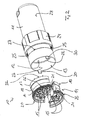
- an exploded view of the cable sleeve according to Fig. 1 can Fig. 2 be removed.
- the cable sleeve 10 of the invention is the Fig. 1 and 2 designed as a hood sleeve and has a cover designed as a cover body 11, according to Fig. 2 an interior 12 of the cable sleeve 10 is defined.
- a sealing body 14 can be inserted, wherein over the sealing body 14 on the one hand fiber optic cable in the interior 12 of the cable sleeve 10 can be inserted and on the other hand the same from the interior 12 executable.
- the seal body 14 of the cable sleeve 10 is in Fig. 3 shown in isolation, in an exploded view.
- the sealing body 14 of the cable sleeve 10 has two dimensionally stable end pieces 16 and 17, between which a compressible gel element 18 is arranged. As Fig. 2 and 3 can be removed, the sealing body 14 is formed in two parts and therefore composed of two halves 19 and 20. In the assembled state of the cable sleeve 10, the dividing plane of the sealing body 14 extends in the longitudinal direction of the cable sleeve 10 or in the longitudinal direction of the cover body 11.
- One of the two halves 19 of the seal body 14 has according to Fig. 2 and 3 formed as a snap hook projections 21 which engage in the assembled state of the seal body 14 in non-illustrated recess of the other half 20 of the seal body 14 and so hold together the two halves 19, 20 of the seal body 14.
- the cover body 11 of the cable sleeve 10 according to the invention has a stop 22, which is formed by a step-like cross-sectional change of an inner wall 23 of the cover body 11.
- the stop 22 limits the insertion depth of the seal body 14 in the interior 12 of the cover body 11, wherein when the seal body 14 rests against the stop 22 with the inner, dimensionally stable end piece 17 in an uncompressed state, the seal body 17 at least partially with the outer, dimensionally stable End piece 16 protrudes from the cover body 11 and protrudes from the same.
- a closure body 24 of the cable sleeve 10 is screwed to the outer, dimensionally stable end 16 of the seal body 14 with compression of the gel member 18, in such a way that is pressed by screwing the outer, rigid end piece 16 against the stop 22 abutting, inner end piece 17 , As Fig. 2 can be removed, the closure body 24 has for this purpose an internal thread 25, via which the closure body 24 can be screwed to an external thread 26 associated with the outer, dimensionally stable end piece 16 of the sealing body 14.
- the closure body 24 is formed, so to speak, as a union nut whose relative displaceability to the covering body 11 is limited by a stop 27, which is formed by a step-like cross-sectional change of an outer wall 28 of the covering body 11.
- the cable sleeve 10 according to the invention furthermore has at least one compensation element 29, via which the force applied by means of the closure body 24 for compressing the gel element 18 of the sealing body 14 can be stored.
- the cable sleeve 10 according to the invention has a single compensation element 29, which is designed as an elastomer ring. In the assembled state of the cable sleeve 10 formed as an elastomeric ring compensation element 29 between the inner, dimensionally stable end portion 17 of the seal body 14 and the cover body 11 formed by the stop 22 is arranged for the seal body 14.
- the compensation element 29 stores the force applied by means of the closure body 24 and permanently exerts a compression pressure on the sealing body 24 or the gel element 18 thereof. This makes it possible to compensate or compensate for a temperature-induced change in the behavior of the gel element 18 of the sealing body 14 and to ensure a good sealing effect of the sealing element 14 over a wide temperature range.
- the installation position of the seal body 14 in the cover body 11 is according to Fig. 2 Defined by the cover body 11 associated projections 30, which in slot-like recesses 31 of the seal body 14 (see Fig. 3 ) are insertable.
- the cover 11 associated with two diametrically opposed projections 30, wherein each of the projections 30 in a slot-like recess 31 of the seal body 14 is inserted.
- the slot-like recesses 31 are assigned to the outer, dimensionally stable end piece 16 of the seal body 14.
- the sealing body 14 When mounting or assembling the cable sleeve 10, therefore, the sealing body 14 is inserted into the opening 13 of the cover body 11, wherein the stop 22 of the cover 11 limits the insertion depth of the seal body 14 in the cover 11.
- the sealing body 14 is then, when the same in an uncompressed state with the inner end piece abuts against the stop 22, at least with the external thread 26 of the outer, dimensionally stable end piece 16 against the cover body 11 in front of or protrudes at least partially out of the same.
- the designed as a union nut closure body 24 is screwed with its internal thread 25 with the external thread 26 of the seal body 14, in this case due to the fact that the sealing body 14 abuts the inner end piece 17 on the stop 22, the gel element 18 of the seal body 14 is compressed.
- the compensation element 29 is also compressed, which stores the force applied to close the cable sleeve 10 via the closure body 24 and keeps the gel element 18 of the sealing body 14 permanently under a compression pressure.
- a temperature-induced change in the behavior of the gel element 18 can be compensated or compensated.
- the compensation element 29 is preferably formed from a thermoplastic elastomer, called TPE for short.
- TPE thermoplastic elastomer
- thermoplastic polyurethane short TPU or PUR suitable.
- terpolymeren elastomer such. B. from ethylene-propylene rubber, EPM for short, or called ethylene-propylene-diene rubber, EPDM short.
- EPDM ethylene-propylene-diene rubber
- the closure body 24 is open at both ends, so that the same in the sense of a union nut relative to the cover 11 can be moved.
- the openings 15 of the seal body 14, which serve the introduction or execution of optical fiber cables in the cable sleeve 10, are therefore not covered by the closure body 24.
- Another special feature of the cable sleeve 10 according to the invention is to be seen in that the inner, dimensionally stable end piece 17 of the seal body 14 adjacent to the openings 15, which serve to insert or run optical fiber cables into or out of the inner space 12 of the cable sleeve 10, web-like projections 32, which form integral Zugabfangungs shame for the optical fiber cable.
Landscapes
- Physics & Mathematics (AREA)
- General Physics & Mathematics (AREA)
- Optics & Photonics (AREA)
- Light Guides In General And Applications Therefor (AREA)
- Mechanical Coupling Of Light Guides (AREA)
- Cable Accessories (AREA)
- Braiding, Manufacturing Of Bobbin-Net Or Lace, And Manufacturing Of Nets By Knotting (AREA)
Description
- Die Erfindung betrifft eine Kabelmuffe zur strukturierten Ablage bzw. Handhabung von in Lichtwellenleiterkabeln geführten Lichtwellenleitern gemäß dem Oberbegriff des Anspruchs 1.
- Kabelmuffen zur strukturierten Ablage bzw. Handhabung von in Lichtwellenleiterkabeln geführten Lichtwellenleitern werden in Lichtwellenleiterkabelnetzen zum Schutz von Spleißverbindungen an Verbindungsstellen von zwei Lichtwellenleiterkabeln sowie zum Schutz der Lichtwellenleiter an Abzweigstellen oder an Aufteilungsstellen von Lichtwellenleiterkabeln verwendet. Dabei müssen die Kabelmuffen die Kontinuität der Lichtwellenleiterkabel so gewährleisten, als wären die Lichtwellenleiterkabel nicht unterbrochen. Der strukturierten Ablage und schonenden Handhabung der Lichtwellenleiter kommt hierbei eine entscheidenden Rolle zu, damit die Übertragungseigenschaften der Lichtwellenleiter nicht negativ beeinträchtigt werden.
- Eine Kabelmuffe mit den Merkmalen des Oberbegriffs des Anspruchs 1 ist aus der
EP 0 646 294 B1 bekannt. So umfasst die dort offenbarte Kabelmuffe einen Abdeckkörper sowie einen in eine Öffnung des Abdeckkörpers einführbaren Dichtungskörper, wobei der Dichtungskörper ein gelartiges Dichtungsmaterial umfasst, welches zwischen zwei formstabilen Platten angeordnet ist. Nach derEP 0 646 294 B1 ist der Dichtungskörper in einem Hohlraum in Axialrichtung nach innen und außen in Bezug auf den Abdeckkörper verschiebbar, um Druckunterschiede zwischen einem Innendruck und Außendruck der Kabelmuffe auszugleichen. Abhängig von diesem Druckunterschied kommt der Dichtungskörper dabei an unterschiedlichen Anschlägen zur Anlage. - Eine weitere Kabelmuffe ist aus der
US 5,455,391 bekannt, die ebenfalls einen Dichtungskörper umfasst, der zwei formstabile Endstücke und ein zwischen den beiden Endstücken angeordnetes, komprimierbares Gelelement umfasst. Nach derUS 5,455,391 ist das Gelelement von Verspannelementen, weiche die beiden formstabilen Endstücke gegeneinander drücken, durchdrungen. - Hiervon ausgehend liegt der vorliegenden Erfindung das Problem zu Grunde, eine neuartige Kabelmuffe zur strukturierten Ablage bzw. Handhabung von in Lichtwellenleiterkabeln geführten Lichtwellenleitern zu schaffen. Dieses Problem wird dadurch gelöst, dass die eingangs genannte Kabelmuffe zur strukturierten Anlage bzw. Handhabung von in Lichtwellenleiterkabeln geführten Lichtwellenleitern durch die Merkmale des kennzeichnenden Teils des Anspruchs 1 weitergebildet ist. Erfindungsgemäß weist der Abdeckkörper einen Anschlag auf, an dem der Dichtungskörper mit einem innenliegenden, formstabilen Endstück anliegt, wobei ein Verschlusskörper mit einem außenliegenden, formstabilen Endstück des Dichtungskörpers unter Komprimierung des Geleiements verschraubbar ist, und wobei mindestens ein Kompensationselement die über den Verschlusskörper aufgebrachte Kraft speichert und auf das Gelelement permanent einen Kompressionsdruck ausübt.
- Die erfindungsgemäße Kabelmuffe zeichnet sich durch einen einfachen Aufbau aus. In die Kabelmuffe einzuführende bzw. aus derselben auszuführende Lichtwellenleiterkabel lassen sich einfach abdichten. Die Abdict tung resultiert aus der Komprimierung des Gelelements und des oder jedes Kompensationselements. Das oder jedes Kompensationselement stellt einen Kompressionsdruck für das Gelelement bereit, um auch bei einer temperaturbedingten Änderung des Verhaltens des Gelelements eine gute Dichtwirkung desselben zu gewährleisten. Das oder jedes Kompensationselement speichert die beim Verschließen der Kabelmuffe über den Verschlusskörper aufgebrachte Kraft und beaufschlagt das Gelelement des Dichtungskörpers permanent mit dem Kompressionsdruck.
- Vorzugsweise ist das oder jedes Kompensationselement als Elastomerring ausgebildet, der zwischen dem innenliegenden Endstück des Dichtungskörpers und dem vom Abdeckkörper gebildeten Anschlag angeordnet ist.
- Nach einer vorteilhaften Weiterbildung weist der Verschlusskörper ein Innengewinde auf, über welches derselbe mit einem dem außenliegenden Endstück des Dichtungskörpers zugeordneten Außengewinde verschraubt ist.
- Bevorzugte Weiterbildungen der Erfindung ergeben sich aus den Unteransprüchen und der nachfolgenden Beschreibung. Ein Ausführungsbeispiel der Erfindung wird, ohne hierauf beschränkt zu sein, anhand der Zeichnung näher erläutert. In der Zeichnung zeigt:
- Fig. 1:
- eine als Haubenmuffe ausgebildete, erfindungsgemäße Kabelmuffe zur strukturierten Ablage bzw. Handhabung von in Lichtwellenleiter- kabeln geführten Lichtwellenleitern in perspektivischer Ansicht,
- Fig. 2:
- die erfindungsgemäße Kabelmuffe gemäß
Fig. 1 in perspektivischer Explosionsansicht, - Fig. 3:
- einen Dichtungskörper der erfindungsgemäßen Kabelmuffe nach
Fig. 1 und2 in perspektivischer Explosionsansicht, und - Fig. 4:
- eine Abdeckhaube der erfindungsgemäßen Kabelmuffe nach
Fig. 1 und2 zusammen mit einem Kompensationselement der Kabelmuffe in perspektivischer Ansicht. - Unter Bezugnahme auf die
Fig. 1 bis 4 wird nachfolgend die Erfindung anhand einer als Haubenmuffe ausgebildeten Kabelmuffe zur strukturierten Ablage bzw. Handhabung von in Lichtwellenleiterkabeln geführten Lichtwellenleitern im Detail beschrieben. Obwohl die Erfindung bei Haubenmuffen besonders vorteilhaft verwendet werden kann, ist die Erfindung auch bei anderen Muffentypen, zum Beispiel bei sogenannten Inline-Muffen, verwendbar. -
Fig. 1 zeigt eine erfindungsgemäße Kabelmuffe 10 in zusammengebautem Zustand, eine Explosionsdarstellung der Kabelmuffe gemäßFig. 1 kannFig. 2 entnommen werden. So ist die erfindungsgemäße Kabelmuffe 10 derFig. 1 und2 als Haubenmuffe ausgebildet und verfügt über einen als Abdeckhaube ausgebildeten Abdeckkörper 11, der gemäßFig. 2 einen Innenraum 12 der Kabelmuffe 10 definiert. In eine Öffnung 13 des Abdeckkörpers 11 ist ein Dichtungskörper 14 einführbar, wobei über den Dichtungskörper 14 einerseits Lichtwellenleiterkabel in den Innenraum 12 der Kabelmuffe 10 einführbar und andererseits dieselben aus dem Innenraum 12 ausführbar sind. Das Einführen bzw. das Ausführen von Lichtwellenleiterkabeln in bzw. aus dem Innenraum 12 der Kabelmuffe 10 erfolgt über in den Dichtungskörper 14 integrierte Öffnungen 15. Der Dichtungskörper 14 der Kabelmuffe 10 ist inFig. 3 in Alleindarstellung gezeigt, und zwar in einer Explosionsdarstellung. - Der Dichtungskörper 14 der erfindungsgemäßen Kabelmuffe 10 verfügt über zwei formstabile Endstücke 16 und 17, zwischen denen ein komprimierbares Gelelement 18 angeordnet ist. Wie
Fig. 2 und3 entnommen werden kann, ist der Dichtungskörper 14 zweiteilig ausgebildet und demnach aus zwei Hälften 19 und 20 zusammengesetzt. In zusammengebautem Zustand der Kabelmuffe 10 verläuft die Teilungsebene des Dichtungskörpers 14 dabei in Längsrichtung der Kabelmuffe 10 bzw. in Längsrichtung des Abdeckkörpers 11. Eine der beiden Hälften 19 des Dichtungskörpers 14 verfügt gemäßFig. 2 und3 über als Schnapphaken ausgebildete Vorsprünge 21, die in zusammengebauten Zustand des Dichtungskörpers 14 in nicht-dargestellte Ausnehmung der anderen Hälfte 20 des Dichtungskörpers 14 eingreifen und so die beiden Hälften 19, 20 des Dichtungskörpers 14 zusammenhalten. - Der Abdeckkörper 11 der erfindungsgemäßen Kabelmuffe 10 weist einen Anschlag 22 auf, der durch eine stufenartige Querschnittsveränderung einer Innenwand 23 des Abdeckkörpers 11 gebildet wird.
- Der Anschlag 22 beschränkt die Einführtiefe des Dichtungskörpers 14 in den Innenraum 12 des Abdeckkörpers 11, wobei dann, wenn der Dichtungskörper 14 mit dem innenliegenden, formstabilen Endstück 17 in einem unkomprimierten Zustand am Anschlag 22 anliegt, der Dichtungskörper 17 zumindest abschnittsweise mit dem außenliegenden, formstabilen Endstück 16 aus dem Abdeckkörper 11 vorsteht bzw. aus demselben herausragt.
- Ein Verschlusskörper 24 der Kabelmuffe 10 ist mit dem außenliegenden, formstabilen Endstück 16 des Dichtungskörpers 14 unter Komprimierung des Gelelements 18 verschraubbar, und zwar derart, dass durch das Verschrauben das außenliegende, formstabile Endstück 16 gegen das am Anschlag 22 anliegende, innenliegende Endstück 17 gedrückt wird. Wie
Fig. 2 entnommen werden kann, verfügt der Verschlusskörper 24 hierzu über ein Innengewinde 25, über welches der Verschlusskörper 24 mit einem dem außenliegenden, formstabilen Endstück 16 des Dichtungskörpers 14 zugeordneten Außengewinde 26 verschraubt werden kann. - Der Verschlusskörper 24 ist sozusagen als Überwurfmutter ausgebildet, dessen Relativverschiebbarkeit zum Abdeckkörper 11 durch einen Anschlag 27 begrenzt wird, der durch eine stufenartige Querschnittsveränderung einer Außenwand 28 des Abdeckkörpers 11 gebildet ist.
- Die erfindungsgemäße Kabelmuffe 10 verfügt weiterhin über mindestens ein Kompensationselement 29, über welches die mit Hilfe des Verschlusskörpers 24 aufgebrachte Kraft zum Komprimieren des Gelelements 18 des Dichtungskörpers 14 gespeichert werden kann. Im gezeigten Ausführungsbeispiel verfügt die erfindungsgemäße Kabelmuffe 10 über ein einziges Kompensationselement 29, welches als Elastomerring ausgebildet ist. In zusammengebautem Zustand der Kabelmuffe 10 ist das als Elastomerring ausgebildete Kompensationselement 29 zwischen dem innenliegenden, formstabilen Endstück 17 des Dichtungskörpers 14 und dem vom Abdeckkörper 11 gebildeten Anschlag 22 für den Dichtungskörper 14 angeordnet.
- Wie bereits erwähnt, speichert das Kompensationselement 29 die mit Hilfe des Verschlusskörpers 24 aufgebrachte Kraft und übt auf den Dichtungskörper 24 bzw. das Gelelement 18 desselben permanent einen Kompressionsdruck 18 aus. Hierdurch ist es möglich, eine temperaturbedingte Änderung des Verhaltens des Gelelements 18 des Dichtungskörpers 14 auszugleichen bzw. zu kompensieren und so über einen breiten Temperaturbereich eine gute Dichtwirkung des Dichtungselements 14 zu gewährleisten.
- Die Einbauposition des Dichtungskörpers 14 im Abdeckkörper 11 wird gemäß
Fig. 2 durch dem Abdeckkörper 11 zugeordnete Vorsprünge 30 definiert, die in schlitzartige Ausnehmungen 31 des Dichtungskörpers 14 (sieheFig. 3 ) einführbar sind. GemäßFig. 2 und4 sind im bevorzugten Ausführungsbeispiel dem Abdeckkörper 11 zwei sich diametral gegenüberliegende Vorsprünge 30 zugeordnet, wobei jeder der Vorsprünge 30 in eine schlitzartige Ausnehmung 31 des Dichtungskörpers 14 einführbar ist. Die schlitzartigen Ausnehmungen 31 sind dabei dem außenliegenden, formstabilen Endstück 16 des Dichtungskörpers 14 zugeordnet. - Bei der Montage bzw. beim Zusammenbau der Kabelmuffe 10 wird demnach der Dichtungskörper 14 in die Öffnung 13 des Abdeckkörpers 11 eingeführt, wobei der Anschlag 22 des Abdeckkörpers 11 die Einführtiefe des Dichtungskörpers 14 in den Abdeckkörper 11 begrenzt. Der Dichtungskörper 14 steht dann, wenn derselbe in einem unkomprimierten Zustand mit dem innenliegenden Endstück am Anschlag 22 anliegt, zumindest mit dem Außengewinde 26 des außenliegenden, formstabilen Endstücks 16 gegenüber dem Abdeckkörper 11 vor bzw. ragt zumindest abschnittsweise aus demselben heraus. Der als Überwurfmutter ausgebildete Verschlusskörper 24 wird mit seinem Innengewinde 25 mit dem Außengewinde 26 des Dichtungskörpers 14 verschraubt, wobei hierbei bedingt dadurch, dass der Dichtungskörper 14 mit dem innenliegenden Endstück 17 am Anschlag 22 anliegt, das Gelelement 18 des Dichtungskörpers 14 komprimiert wird.
- Hierbei wird auch das Kompensationselement 29 komprimiert, welches die zum Verschließen der Kabelmuffe 10 über den Verschlusskörper 24 aufgebrachte Kraft speichert und das Gelelement 18 des Dichtungskörpers 14 permanent unter einem Kompressionsdruck hält. Hierdurch kann eine temperaturbedingte Änderung des Verhaltens des Gelelements 18 ausgeglichen bzw. kompensiert werden.
- Das Kompensationselement 29 ist vorzugsweise aus einem thermoplastischen Elastomer, kurz TPE genannt, gebildet. Als thermoplastisches Elastomer ist insbesondere thermoplastisches Polyuretan, kurz TPU bzw. PUR, geeignet. Ebenso ist es möglich, das Kompensationselement 29 aus einem terpolymeren Elastomer herzustellen, so z. B. aus Ethylen-Propylen-Kautschuk, kurz EPM genannt, oder aus Ethylen-Propylen-Dien-Kautschuk, kurz EPDM genannt. Weiterhin ist es möglich, das Kompensationselement 29 aus einem SilikonElastomer auszubilden.
- Der Verschlusskörper 24 ist an beiden Enden offen ausgebildet, so dass derselbe im Sinne einer Überwurfmutter relativ zum Abdeckkörper 11 verschoben werden kann. Die Öffnungen 15 des Dichtungskörpers 14, die der Einführung bzw. Ausführung von Lichtwellenleiterkabeln in die Kabelmuffe 10 dienen, werden demnach vom Verschlusskörper 24 nicht verdeckt.
- Eine weitere Besonderheit der erfindungsgemäßen Kabelmuffe 10 ist darin zu sehen, dass das innenliegende, formstabile Endstück 17 des Dichtungskörpers 14 benachbart zu den Öffnungen 15, die dem Einführen bzw. Ausführen von Lichtwellenleiterkabeln in bzw. aus dem Innenraum 12 der Kabelmuffe 10 dienen, stegartige Vorsprünge 32 aufweist, die integrale Zugabfangungselemente für die Lichtwellenleiterkabel bilden.
-
- 10
- Kabelmuffe
- 11
- Abdeckkörper
- 12
- Innenraum
- 13
- Öffnung
- 14
- Dichtungskörper
- 15
- Öffnung
- 16
- Endstück
- 17
- Endstück
- 18
- Gelelement
- 19
- Hälfte
- 20
- Hälfte
- 21
- Vorsprung
- 22
- Anschlag
- 23
- Innenwand
- 24
- Verschlusskörper
- 25
- Innengewinde
- 26
- Außengewinde
- 27
- Anschlag
- 28
- Außenwand
- 29
- Kompensationselement
- 30
- Vorsprünge
- 31
- Ausnehmung
- 32
- Vorsprung
Claims (9)
- Kabelmuffe zur strukturierten Ablage bzw. Handhabung von in Lichtwellenleiterkabeln geführten Lichtwellenleitern, insbesondere Haubenmuffe, mit einem einen Innenraum (12) definierenden Abdeckkörper (11), insbesondere einer Abdeckhaube, und mit einem in eine Öffnung (13) des Abdeckkörpers (11) einführbaren, der Einführung von Lichtwellenleiterkabeln in den Innenraum (12) und/oder der Ausführung von Lichtwellenleiterkabeln aus dem Innenraum (12) dienenden Dichtungskörper (14), der zwei formstabile Endstücke (16, 17) und ein zwischen den Endstücken angeordnetes, komprimierbares Gelelement (18) umfasst, wobei der Abdeckkörper (11) einen Anschlag (22) aufweist, an dem der Dichtungskörper (14) mit einem innenliegenden, formstabilen Endstück (17) anliegt, wobei ein Verschlusskörper (24) mit einem außenliegenden, formstabilen Endstück (16) des Dichtungskörpers (14) unter Komprimierung des Gelelements (18) verschraubbar ist, und dass mindestens ein Kompensationselement (29) die über den Verschlusskörper (24) aufgebrachte Kraft speichert und auf das Gelelement (18) permanent einen Kompressionsdruck ausübt.
- Kabelmuffe nach Anspruch 1, dadurch gekennzeichnet, dass das oder jedes Kompensationselement (29) als Elastomerring ausgebildet ist, der zwischen dem innenliegenden, formstabilen Endstück (17) des Dichtungskörpers (14) und dem vom Abdeckkörper (11) gebildeten Anschlag (22) angeordnet ist.
- Kabelmuffe nach Anspruch 1 oder 2, dadurch gekennzeichnet, dass der Verschlusskörper (24) ein Innengewinde (25) aufweist, über welches derselbe mit einem dem außenliegenden, formstabilen Endstück (16) des Dichtungskörpers (14) zugeordneten Außengewinde (26) verschraubt ist.
- Kabelmuffe nach einem oder mehreren der Ansprüche 1 bis 3, dadurch gekennzeichnet, dass der Verschlusskörper (24) als Überwurfmutter ausgebildet ist.
- Kabelmuffe nach einem oder mehreren der Ansprüche 1 bis 4, dadurch gekennzeichnet, dass der Anschlag (22) von einer stufenartigen Querschnittsveränderung einer Innenwand (23) des Abdeckkörpers (11) gebildet ist, wobei der Anschlag (22) die Einführtiefe des Dichtungskörpers (14) in den Innenraum (12) des Abdeckkörpers (11) beschränkt.
- Kabelmuffe nach einem oder mehreren der Ansprüche 1 bis 5, dadurch gekennzeichnet, dass die Einführposition bzw. Einbauposition des Dichtungskörpers (14) relativ zum Abdeckkörper (11) durch mindestens einen dem Abdeckkörper (11) zugeordneten Vorsprung (30) und mindestens eine dem Dichtungskörper (14) zugeordnete Ausnehmung (31) bestimmt ist, derart, dass bei zusammengebauter Kabelmuffe der oder jeder Vorsprung (30) des Abdeckkörpers (11) in eine entsprechende Ausnehmung (31) des Dichtungskörpers (14) eingreift.
- Kabelmuffe nach einem oder mehreren der Ansprüche 1 bis 6, dadurch gekennzeichnet, dass der Dichtungskörper (14) derart zweiteilig ausgebildet ist, dass eine Teilungsebene desselben in Längsrichtung der Kabelmuffe verläuft.
- Kabelmuffe nach Anspruch 7, dadurch gekennzeichnet, dass mindestens einer Hälfte (19) des Dichtungskörpers (14) mindestens ein als Schnapphaken ausgebildeter Vorsprung (21) zugeordnet ist, der in einem zusammengebauten Zustand des Dichtungskörpers (14) in eine Ausnehmung der jeweils anderen Hälfte (20) des Dichtungskörpers (14) eingreift und so die beiden Hälften (19, 20) des Dichtungskörpers (14) zusammenhält.
- Kabelmuffe nach einem oder mehreren der Ansprüche 1 bis 8, dadurch gekennzeichnet, dass das innenliegende, formstabile Endstück (17) des Dichtungskörpers (14) benachbart zu Öffnungen (15), die dem Einführen bzw. Ausführen von Lichtwellenleiterkabeln in bzw. aus dem Innenraum (12) der Kabelmuffe (10) dienen, Vorsprünge (32) aufweist, die integrale Zugabfangungselemente für die Lichtwellenleiterkabel bilden.
Applications Claiming Priority (2)
| Application Number | Priority Date | Filing Date | Title |
|---|---|---|---|
| DE202006008654U DE202006008654U1 (de) | 2006-05-30 | 2006-05-30 | Kabelmuffe zur strukturierten Ablage bzw. Handhabung von in Lichtwellenleiterkabeln geführten Lichtwellenleitern |
| PCT/EP2007/004478 WO2007137718A1 (de) | 2006-05-30 | 2007-05-19 | Kabelmuffe zur strukturierten ablage bzw. handhabung von in lichtwellenleiterkabeln geführten lichtwellenleitern |
Publications (2)
| Publication Number | Publication Date |
|---|---|
| EP2021850A1 EP2021850A1 (de) | 2009-02-11 |
| EP2021850B1 true EP2021850B1 (de) | 2010-07-07 |
Family
ID=36848693
Family Applications (1)
| Application Number | Title | Priority Date | Filing Date |
|---|---|---|---|
| EP07725386A Not-in-force EP2021850B1 (de) | 2006-05-30 | 2007-05-19 | Kabelmuffe zur strukturierten ablage bzw. handhabung von in lichtwellenleiterkabeln geführten lichtwellenleitern |
Country Status (6)
| Country | Link |
|---|---|
| US (1) | US8055114B2 (de) |
| EP (1) | EP2021850B1 (de) |
| AT (1) | ATE473462T1 (de) |
| DE (2) | DE202006008654U1 (de) |
| ES (1) | ES2347710T3 (de) |
| WO (1) | WO2007137718A1 (de) |
Cited By (1)
| Publication number | Priority date | Publication date | Assignee | Title |
|---|---|---|---|---|
| CN102540373A (zh) * | 2012-03-12 | 2012-07-04 | 南京云控通信科技有限公司 | 一种用于小规格光缆外皮紧固装置 |
Families Citing this family (17)
| Publication number | Priority date | Publication date | Assignee | Title |
|---|---|---|---|---|
| AU2001241738A1 (en) * | 2000-02-25 | 2001-09-03 | Corixa Corporation | Compounds and methods for diagnosis and immunotherapy of tuberculosis |
| WO2005088373A1 (en) * | 2004-03-08 | 2005-09-22 | Adc Telecommunications, Inc. | Fiber access terminal |
| DE102008032753B4 (de) * | 2008-07-11 | 2010-05-27 | Adc Gmbh | Adapter für Muffen mit Elastomer-Kabelabdichtungen und Verfahren zur Einführung eines Lichtwellenleiterkabels in eine Muffe |
| DE202009014264U1 (de) | 2009-10-21 | 2010-01-07 | CCS Technology, Inc., Wilmington | Verteilereinrichtung für Nachrichtenkabel |
| DK2330706T3 (da) | 2009-12-03 | 2017-08-21 | CommScope Connectivity Belgium BVBA | Geletætningsenhed |
| DE202011110642U1 (de) | 2010-09-21 | 2016-03-17 | Huber + Suhner Ag | Umwelttauglich abgedichtete Kabelpeitschen-Anordnungen |
| AP2014008025A0 (en) | 2012-04-03 | 2014-10-31 | Tyco Electronics Raychem Bvba | Telecommunications enclosure and organizer |
| DK3176890T3 (da) | 2012-07-02 | 2020-05-18 | CommScope Connectivity Belgium BVBA | Kabeltætningsenhed med flere tætningsmoduler |
| DE202012013316U1 (de) * | 2012-12-18 | 2016-03-11 | Reichle & De-Massari Ag | Kabelkontaktierungswitterungsschutz |
| DE102013114533A1 (de) * | 2013-12-19 | 2015-06-25 | Reichle & De-Massari Ag | Dichtmodul |
| US10125900B2 (en) * | 2016-01-20 | 2018-11-13 | Gary Penrod | Device to prevent entry by rodents and other such pests into a recreational vehicle's service compartment |
| DE102018102295A1 (de) * | 2018-02-01 | 2019-08-01 | Reichle & De-Massari Ag | Kabelmuffenvorrichtung |
| US11837816B2 (en) * | 2018-05-31 | 2023-12-05 | Hydra-Electric Company | Method of sealing cable exit for moisture and vapor intrusion |
| WO2021152145A1 (en) * | 2020-01-31 | 2021-08-05 | CommScope Connectivity Belgium BV | Cable sealing unit with multiple configurations |
| USD971160S1 (en) * | 2020-09-04 | 2022-11-29 | Juice Technology AG | Female electric vehicle charging connector |
| USD971159S1 (en) * | 2020-09-04 | 2022-11-29 | Juice Technology AG | Male electric vehicle charging connector |
| CN114964027B (zh) * | 2022-04-29 | 2025-04-01 | 太原理工大学 | 一种边坡测斜管变形监测系统 |
Family Cites Families (52)
| Publication number | Priority date | Publication date | Assignee | Title |
|---|---|---|---|---|
| US3848074A (en) * | 1973-04-13 | 1974-11-12 | W Channell | Terminal and splice enclosure for cable installations |
| DE3726718A1 (de) | 1986-04-07 | 1989-02-23 | Siemens Ag | Vorrichtung zum anbringen einer mechanischen verbindung am kabelmantel eines optischen kabels |
| DE3726719A1 (de) | 1986-04-07 | 1989-02-23 | Siemens Ag | Vorrichtung zum anbringen einer mechanischen verbindung am kabelmantel eines optischen kabels |
| US5055636A (en) * | 1990-05-31 | 1991-10-08 | Reliance Comm/Tec Corporation | Sealed reenterable splice enclosure |
| US5097529A (en) | 1991-03-22 | 1992-03-17 | At&T Bell Laboratories | Space-saving optical fiber cable closure |
| EP0587621A1 (de) | 1991-06-06 | 1994-03-23 | N.V. Raychem S.A. | Kabelabdichtung |
| GB9112181D0 (en) | 1991-06-06 | 1991-07-24 | Raychem Sa Nv | Cable sealing |
| GB9212625D0 (en) | 1992-06-15 | 1992-07-29 | Raychem Sa Nv | Cable sealing device |
| GB9212624D0 (en) | 1992-06-15 | 1992-07-29 | Raychem Sa Nv | Cable sealing device |
| DE4231181C1 (en) | 1992-09-17 | 1993-08-26 | Siemens Ag, 8000 Muenchen, De | Cable restraint for fibre=optic cable distribution box - comprises U=shaped fixing shell fastened to rail which mounts screw for fixing cable central strain element |
| US5479554A (en) | 1994-01-11 | 1995-12-26 | Windsor Communications | Splice closure apparatus for continuous optical ground wire communications cable and splicing system |
| US5446823A (en) | 1994-01-26 | 1995-08-29 | Raychem Corporation | Aerial, pedestal, below grade, or buried optical fiber closure |
| GB9404396D0 (en) * | 1994-03-07 | 1994-04-20 | Raychem Sa Nv | Sealing arrangement |
| GB9405535D0 (en) | 1994-03-21 | 1994-05-04 | Raychem Sa Nv | Splice organizing apparatus |
| ATE187256T1 (de) | 1994-07-21 | 1999-12-15 | Rxs Schrumpftech Garnituren | Abfangsvorrichtung für optische kabel |
| US5793921A (en) | 1995-03-20 | 1998-08-11 | Psi Telecommunications, Inc. | Kit and method for converting a conductive cable closure to a fiber optic cable closure |
| TW286371B (de) | 1995-03-31 | 1996-09-21 | Minnesota Mining & Mfg | |
| NZ303594A (en) | 1995-03-31 | 1999-01-28 | Minnesota Mining & Mfg | Optical fibre splice tray arrangement |
| US5617501A (en) | 1995-03-31 | 1997-04-01 | Minnesota Mining And Manufacturing Company | Shield bond strain connector for fiber optic closure |
| KR100418847B1 (ko) | 1995-04-12 | 2004-04-21 | 에르익스에스 게젤샤프트 푀르퍼뫼겐스퍼발퉁 엠바하 | 후드슬리브 |
| DE69637538D1 (de) | 1995-09-29 | 2008-07-03 | Minnesota Mining & Mfg | |
| US5598499A (en) * | 1995-11-01 | 1997-01-28 | Lucent Technologies, Inc. | Seal for cable splice closure |
| US5652820A (en) | 1995-11-13 | 1997-07-29 | Act Communications, Inc. | Fiber optic splice closure and protection apparatus |
| FR2748867B1 (fr) | 1996-05-15 | 1998-06-19 | Alcatel Cable Interface | Dispositif d'etancheite de cables dans un acces |
| GB9617591D0 (en) | 1996-08-22 | 1996-10-02 | Raychem Sa Nv | Optical fibre splice closure |
| DE19645846A1 (de) | 1996-11-07 | 1998-05-14 | Psi Products Gmbh | Bausatz zur Erzeugung einer Muffe für Verteilernetze der Telekommunikation od.dgl. |
| US5774618A (en) | 1996-12-19 | 1998-06-30 | Lucent Technologies Inc. | Compact closure for optical fiber cable |
| DE19728370A1 (de) | 1997-07-03 | 1999-01-07 | Bosch Gmbh Robert | Kabeldurchführung für Anschlußkabel eines Gasmeßfühlers |
| AU9732998A (en) | 1997-12-22 | 1999-07-12 | Huber & Suhner Ag | Cable sleeve |
| GB9805965D0 (en) * | 1998-03-21 | 1998-05-20 | Cannon Telecomms Limited | Single-ended joint cable sealing system |
| CA2327704A1 (en) * | 1998-04-28 | 1999-11-04 | Dirk Deroost | A closure |
| US6175083B1 (en) | 1998-12-11 | 2001-01-16 | Caterpillar Inc. | Sealing a lead from a confined cavity of an apparatus |
| US6321021B1 (en) * | 1999-07-12 | 2001-11-20 | Ocean Design, Inc. | End seal assembly for tubular conduit |
| US6411767B1 (en) | 1999-08-24 | 2002-06-25 | Corning Cable Systems Llc | Optical fiber interconnection closures |
| US6292614B1 (en) | 1999-08-24 | 2001-09-18 | Siecor Operations, Llc | Movable bracket for holding internal components of an optical fiber interconnection closure during servicing and associated method |
| US6315461B1 (en) * | 1999-10-14 | 2001-11-13 | Ocean Design, Inc. | Wet mateable connector |
| US6533472B1 (en) | 1999-10-19 | 2003-03-18 | Alcoa Fujikura Limited | Optical fiber splice closure assembly |
| CN1311600C (zh) | 1999-12-02 | 2007-04-18 | Ccs技术公司 | 用于纵向分体电缆配件的密封体 |
| DE10010452A1 (de) | 1999-12-02 | 2001-06-07 | Rxs Kabelgarnituren Gmbh & Co | Dichtungskörper für längsgeteilte Kabelgarnituren |
| AU2002213249A1 (en) * | 2000-10-17 | 2002-04-29 | Preformed Line Products Company | Cable closure and assembly |
| US6628880B2 (en) | 2001-04-06 | 2003-09-30 | Windsor Communications, Inc. | Fiber optic cable splice enclosure |
| CN1307444C (zh) | 2001-05-25 | 2007-03-28 | 预制管线产品公司 | 光纤电缆罩和组件 |
| DE10338848A1 (de) | 2003-08-20 | 2005-03-17 | CCS Technology, Inc., Wilmington | Abfangvorrichtung für optische Kabel, Kabelmuffe mit einer solchen Abfangvorrichtung und Verfahren zur Bereitstellung einer Abfangung für optische Kabel unter Verwendung einer solchen Abfangvorrichtung |
| DE202005009932U1 (de) | 2005-06-22 | 2005-11-24 | CCS Technology, Inc., Wilmington | Vorrichtung zur Abfangung von in Mikroducts geführten Mikrokabeln sowie der Mikroducts |
| US8422835B2 (en) * | 2005-06-30 | 2013-04-16 | Weatherford/Lamb, Inc. | Optical waveguide feedthrough assembly |
| US7045710B1 (en) | 2005-08-31 | 2006-05-16 | 3M Innovative Properties Company | Enclosure for telecommunication lines and splices |
| DE202005014677U1 (de) | 2005-09-16 | 2005-11-17 | CCS Technology, Inc., Wilmington | Vorrichtung zur Abfangung von Kabeln |
| US7308183B2 (en) | 2006-01-04 | 2007-12-11 | Adc Telecommunications, Inc. | Fiber access terminal including moisture barrier plate |
| US7330628B1 (en) | 2006-10-23 | 2008-02-12 | Adc Telecommunications, Inc. | Fiber access terminal including moisture barrier plate with punch out |
| DE102007010853B4 (de) | 2007-03-01 | 2009-01-29 | Adc Gmbh | Verteilereinrichtung für Lichtwellenleiter |
| DE102007010854B4 (de) | 2007-03-01 | 2009-01-08 | Adc Gmbh | Konsole für eine Verteilereinrichtung für Lichtwellenleiter-Kabel |
| DE102007010863B4 (de) | 2007-03-01 | 2009-01-08 | Adc Gmbh | Muffe für Lichtwellenleiter-Kabel |
-
2006
- 2006-05-30 DE DE202006008654U patent/DE202006008654U1/de not_active Expired - Lifetime
-
2007
- 2007-05-19 DE DE502007004334T patent/DE502007004334D1/de active Active
- 2007-05-19 WO PCT/EP2007/004478 patent/WO2007137718A1/de not_active Ceased
- 2007-05-19 AT AT07725386T patent/ATE473462T1/de active
- 2007-05-19 EP EP07725386A patent/EP2021850B1/de not_active Not-in-force
- 2007-05-19 ES ES07725386T patent/ES2347710T3/es active Active
-
2008
- 2008-11-26 US US12/323,530 patent/US8055114B2/en active Active
Cited By (2)
| Publication number | Priority date | Publication date | Assignee | Title |
|---|---|---|---|---|
| CN102540373A (zh) * | 2012-03-12 | 2012-07-04 | 南京云控通信科技有限公司 | 一种用于小规格光缆外皮紧固装置 |
| CN102540373B (zh) * | 2012-03-12 | 2014-03-05 | 南京云控通信科技有限公司 | 一种用于小规格光缆外皮紧固装置 |
Also Published As
| Publication number | Publication date |
|---|---|
| US20090103876A1 (en) | 2009-04-23 |
| DE202006008654U1 (de) | 2006-08-03 |
| WO2007137718A1 (de) | 2007-12-06 |
| ATE473462T1 (de) | 2010-07-15 |
| US8055114B2 (en) | 2011-11-08 |
| DE502007004334D1 (de) | 2010-08-19 |
| ES2347710T3 (es) | 2010-11-03 |
| EP2021850A1 (de) | 2009-02-11 |
Similar Documents
| Publication | Publication Date | Title |
|---|---|---|
| EP2021850B1 (de) | Kabelmuffe zur strukturierten ablage bzw. handhabung von in lichtwellenleiterkabeln geführten lichtwellenleitern | |
| EP2021849A1 (de) | Kabelmuffe zur strukturierten ablage bzw. handhabung von in lichtwellenleiterkabeln geführten lichtwellenleitern | |
| EP2005230B1 (de) | Dichtungskörper einer kabelmuffe | |
| DE69503483T2 (de) | Abdichtungsanordnung | |
| DE69215269T2 (de) | Kabelverschlussvorrichtung mit einer verbesserten Dichtungsbuchse | |
| DE202006006019U1 (de) | Dichtungskörper einer Kabelmuffe | |
| EP2385599B1 (de) | Inline-Kabelmuffe | |
| EP2251729B1 (de) | Kabelmuffe mit Kabelabdichtvorrichtung | |
| WO2014095462A1 (de) | Kabelkontaktierungswitterungsschutz | |
| EP3726267B1 (de) | Einzelrohrabdichtung und kunststoffrohr | |
| DE102012105067A1 (de) | Kabelrohrdichtungsvorrichtung | |
| DE102006046488B4 (de) | Abgedichteter elektrischer Anschluss eines Gehäuses einer elektrischen Steuereinheit und Hydraulikmaschine mit einem Gehäuse mit einem derartigen Anschluss | |
| DE202007014971U1 (de) | Kabelmuffe | |
| CH714248B1 (de) | Mehrteiliges Gehäuse für Verbrauchszähler sowie Sicherungseinrichtung für mehrteilige Gehäuse. | |
| EP2057495B1 (de) | Kabelmuffe | |
| DE10021882B4 (de) | LWL-Klemme | |
| DE3329904C2 (de) | ||
| DE20308264U1 (de) | Lichtwellenleiter-Steckverbindung | |
| DE102005014373B3 (de) | Elektrische Steckvorrichtung | |
| EP2054747B1 (de) | Kabelmuffe | |
| DE19947207A1 (de) | Dichtungselement und Verfahren zur Herstellung | |
| DE102008063192A1 (de) | Kabeldurchführung zur Durchführung eines Kabels durch eine Gehäusewand | |
| DE202015106891U1 (de) | Kabeldurchführung, insbesondere für ein elektronisches Gerät | |
| DE102020115040A1 (de) | Leitungsdurchführungsvorrichtung |
Legal Events
| Date | Code | Title | Description |
|---|---|---|---|
| PUAI | Public reference made under article 153(3) epc to a published international application that has entered the european phase |
Free format text: ORIGINAL CODE: 0009012 |
|
| 17P | Request for examination filed |
Effective date: 20081105 |
|
| AK | Designated contracting states |
Kind code of ref document: A1 Designated state(s): AT BE BG CH CY CZ DE DK EE ES FI FR GB GR HU IE IS IT LI LT LU LV MC MT NL PL PT RO SE SI SK TR |
|
| AX | Request for extension of the european patent |
Extension state: AL BA HR MK RS |
|
| GRAP | Despatch of communication of intention to grant a patent |
Free format text: ORIGINAL CODE: EPIDOSNIGR1 |
|
| GRAS | Grant fee paid |
Free format text: ORIGINAL CODE: EPIDOSNIGR3 |
|
| GRAA | (expected) grant |
Free format text: ORIGINAL CODE: 0009210 |
|
| AK | Designated contracting states |
Kind code of ref document: B1 Designated state(s): AT BE BG CH CY CZ DE DK EE ES FI FR GB GR HU IE IS IT LI LT LU LV MC MT NL PL PT RO SE SI SK TR |
|
| REG | Reference to a national code |
Ref country code: GB Ref legal event code: FG4D Free format text: NOT ENGLISH |
|
| REG | Reference to a national code |
Ref country code: CH Ref legal event code: EP |
|
| REG | Reference to a national code |
Ref country code: IE Ref legal event code: FG4D |
|
| REF | Corresponds to: |
Ref document number: 502007004334 Country of ref document: DE Date of ref document: 20100819 Kind code of ref document: P |
|
| REG | Reference to a national code |
Ref country code: NL Ref legal event code: VDEP Effective date: 20100707 |
|
| REG | Reference to a national code |
Ref country code: ES Ref legal event code: FG2A Ref document number: 2347710 Country of ref document: ES Kind code of ref document: T3 |
|
| PG25 | Lapsed in a contracting state [announced via postgrant information from national office to epo] |
Ref country code: SI Free format text: LAPSE BECAUSE OF FAILURE TO SUBMIT A TRANSLATION OF THE DESCRIPTION OR TO PAY THE FEE WITHIN THE PRESCRIBED TIME-LIMIT Effective date: 20100707 |
|
| LTIE | Lt: invalidation of european patent or patent extension |
Effective date: 20100707 |
|
| PG25 | Lapsed in a contracting state [announced via postgrant information from national office to epo] |
Ref country code: NL Free format text: LAPSE BECAUSE OF FAILURE TO SUBMIT A TRANSLATION OF THE DESCRIPTION OR TO PAY THE FEE WITHIN THE PRESCRIBED TIME-LIMIT Effective date: 20100707 Ref country code: FI Free format text: LAPSE BECAUSE OF FAILURE TO SUBMIT A TRANSLATION OF THE DESCRIPTION OR TO PAY THE FEE WITHIN THE PRESCRIBED TIME-LIMIT Effective date: 20100707 Ref country code: LT Free format text: LAPSE BECAUSE OF FAILURE TO SUBMIT A TRANSLATION OF THE DESCRIPTION OR TO PAY THE FEE WITHIN THE PRESCRIBED TIME-LIMIT Effective date: 20100707 |
|
| REG | Reference to a national code |
Ref country code: IE Ref legal event code: FD4D |
|
| PG25 | Lapsed in a contracting state [announced via postgrant information from national office to epo] |
Ref country code: IS Free format text: LAPSE BECAUSE OF FAILURE TO SUBMIT A TRANSLATION OF THE DESCRIPTION OR TO PAY THE FEE WITHIN THE PRESCRIBED TIME-LIMIT Effective date: 20101107 Ref country code: PT Free format text: LAPSE BECAUSE OF FAILURE TO SUBMIT A TRANSLATION OF THE DESCRIPTION OR TO PAY THE FEE WITHIN THE PRESCRIBED TIME-LIMIT Effective date: 20101108 Ref country code: BG Free format text: LAPSE BECAUSE OF FAILURE TO SUBMIT A TRANSLATION OF THE DESCRIPTION OR TO PAY THE FEE WITHIN THE PRESCRIBED TIME-LIMIT Effective date: 20101007 Ref country code: PL Free format text: LAPSE BECAUSE OF FAILURE TO SUBMIT A TRANSLATION OF THE DESCRIPTION OR TO PAY THE FEE WITHIN THE PRESCRIBED TIME-LIMIT Effective date: 20100707 Ref country code: CY Free format text: LAPSE BECAUSE OF FAILURE TO SUBMIT A TRANSLATION OF THE DESCRIPTION OR TO PAY THE FEE WITHIN THE PRESCRIBED TIME-LIMIT Effective date: 20100707 |
|
| PG25 | Lapsed in a contracting state [announced via postgrant information from national office to epo] |
Ref country code: LV Free format text: LAPSE BECAUSE OF FAILURE TO SUBMIT A TRANSLATION OF THE DESCRIPTION OR TO PAY THE FEE WITHIN THE PRESCRIBED TIME-LIMIT Effective date: 20100707 Ref country code: SE Free format text: LAPSE BECAUSE OF FAILURE TO SUBMIT A TRANSLATION OF THE DESCRIPTION OR TO PAY THE FEE WITHIN THE PRESCRIBED TIME-LIMIT Effective date: 20100707 Ref country code: GR Free format text: LAPSE BECAUSE OF FAILURE TO SUBMIT A TRANSLATION OF THE DESCRIPTION OR TO PAY THE FEE WITHIN THE PRESCRIBED TIME-LIMIT Effective date: 20101008 |
|
| PG25 | Lapsed in a contracting state [announced via postgrant information from national office to epo] |
Ref country code: IE Free format text: LAPSE BECAUSE OF FAILURE TO SUBMIT A TRANSLATION OF THE DESCRIPTION OR TO PAY THE FEE WITHIN THE PRESCRIBED TIME-LIMIT Effective date: 20100707 Ref country code: DK Free format text: LAPSE BECAUSE OF FAILURE TO SUBMIT A TRANSLATION OF THE DESCRIPTION OR TO PAY THE FEE WITHIN THE PRESCRIBED TIME-LIMIT Effective date: 20100707 |
|
| PLBE | No opposition filed within time limit |
Free format text: ORIGINAL CODE: 0009261 |
|
| STAA | Information on the status of an ep patent application or granted ep patent |
Free format text: STATUS: NO OPPOSITION FILED WITHIN TIME LIMIT |
|
| PG25 | Lapsed in a contracting state [announced via postgrant information from national office to epo] |
Ref country code: RO Free format text: LAPSE BECAUSE OF FAILURE TO SUBMIT A TRANSLATION OF THE DESCRIPTION OR TO PAY THE FEE WITHIN THE PRESCRIBED TIME-LIMIT Effective date: 20100707 Ref country code: SK Free format text: LAPSE BECAUSE OF FAILURE TO SUBMIT A TRANSLATION OF THE DESCRIPTION OR TO PAY THE FEE WITHIN THE PRESCRIBED TIME-LIMIT Effective date: 20100707 Ref country code: CZ Free format text: LAPSE BECAUSE OF FAILURE TO SUBMIT A TRANSLATION OF THE DESCRIPTION OR TO PAY THE FEE WITHIN THE PRESCRIBED TIME-LIMIT Effective date: 20100707 Ref country code: EE Free format text: LAPSE BECAUSE OF FAILURE TO SUBMIT A TRANSLATION OF THE DESCRIPTION OR TO PAY THE FEE WITHIN THE PRESCRIBED TIME-LIMIT Effective date: 20100707 |
|
| 26N | No opposition filed |
Effective date: 20110408 |
|
| REG | Reference to a national code |
Ref country code: DE Ref legal event code: R097 Ref document number: 502007004334 Country of ref document: DE Effective date: 20110408 |
|
| PG25 | Lapsed in a contracting state [announced via postgrant information from national office to epo] |
Ref country code: MT Free format text: LAPSE BECAUSE OF FAILURE TO SUBMIT A TRANSLATION OF THE DESCRIPTION OR TO PAY THE FEE WITHIN THE PRESCRIBED TIME-LIMIT Effective date: 20100707 Ref country code: MC Free format text: LAPSE BECAUSE OF NON-PAYMENT OF DUE FEES Effective date: 20110531 |
|
| REG | Reference to a national code |
Ref country code: CH Ref legal event code: PL |
|
| PG25 | Lapsed in a contracting state [announced via postgrant information from national office to epo] |
Ref country code: LI Free format text: LAPSE BECAUSE OF NON-PAYMENT OF DUE FEES Effective date: 20110531 Ref country code: CH Free format text: LAPSE BECAUSE OF NON-PAYMENT OF DUE FEES Effective date: 20110531 |
|
| PG25 | Lapsed in a contracting state [announced via postgrant information from national office to epo] |
Ref country code: LU Free format text: LAPSE BECAUSE OF NON-PAYMENT OF DUE FEES Effective date: 20110519 |
|
| REG | Reference to a national code |
Ref country code: AT Ref legal event code: MM01 Ref document number: 473462 Country of ref document: AT Kind code of ref document: T Effective date: 20120519 |
|
| PG25 | Lapsed in a contracting state [announced via postgrant information from national office to epo] |
Ref country code: AT Free format text: LAPSE BECAUSE OF NON-PAYMENT OF DUE FEES Effective date: 20120519 |
|
| PG25 | Lapsed in a contracting state [announced via postgrant information from national office to epo] |
Ref country code: TR Free format text: LAPSE BECAUSE OF FAILURE TO SUBMIT A TRANSLATION OF THE DESCRIPTION OR TO PAY THE FEE WITHIN THE PRESCRIBED TIME-LIMIT Effective date: 20100707 |
|
| PG25 | Lapsed in a contracting state [announced via postgrant information from national office to epo] |
Ref country code: HU Free format text: LAPSE BECAUSE OF FAILURE TO SUBMIT A TRANSLATION OF THE DESCRIPTION OR TO PAY THE FEE WITHIN THE PRESCRIBED TIME-LIMIT Effective date: 20100707 |
|
| REG | Reference to a national code |
Ref country code: FR Ref legal event code: PLFP Year of fee payment: 10 |
|
| REG | Reference to a national code |
Ref country code: FR Ref legal event code: PLFP Year of fee payment: 11 |
|
| REG | Reference to a national code |
Ref country code: FR Ref legal event code: PLFP Year of fee payment: 12 |
|
| PGFP | Annual fee paid to national office [announced via postgrant information from national office to epo] |
Ref country code: BE Payment date: 20200421 Year of fee payment: 14 |
|
| REG | Reference to a national code |
Ref country code: BE Ref legal event code: MM Effective date: 20210531 |
|
| PG25 | Lapsed in a contracting state [announced via postgrant information from national office to epo] |
Ref country code: BE Free format text: LAPSE BECAUSE OF NON-PAYMENT OF DUE FEES Effective date: 20210531 |
|
| REG | Reference to a national code |
Ref country code: FR Ref legal event code: PLFP Year of fee payment: 17 |
|
| PGFP | Annual fee paid to national office [announced via postgrant information from national office to epo] |
Ref country code: IT Payment date: 20230510 Year of fee payment: 17 Ref country code: FR Payment date: 20230412 Year of fee payment: 17 Ref country code: ES Payment date: 20230608 Year of fee payment: 17 Ref country code: DE Payment date: 20230412 Year of fee payment: 17 |
|
| PGFP | Annual fee paid to national office [announced via postgrant information from national office to epo] |
Ref country code: GB Payment date: 20230412 Year of fee payment: 17 |
|
| REG | Reference to a national code |
Ref country code: DE Ref legal event code: R119 Ref document number: 502007004334 Country of ref document: DE |
|
| GBPC | Gb: european patent ceased through non-payment of renewal fee |
Effective date: 20240519 |
|
| PG25 | Lapsed in a contracting state [announced via postgrant information from national office to epo] |
Ref country code: DE Free format text: LAPSE BECAUSE OF NON-PAYMENT OF DUE FEES Effective date: 20241203 |
|
| PG25 | Lapsed in a contracting state [announced via postgrant information from national office to epo] |
Ref country code: FR Free format text: LAPSE BECAUSE OF NON-PAYMENT OF DUE FEES Effective date: 20240531 |
|
| PG25 | Lapsed in a contracting state [announced via postgrant information from national office to epo] |
Ref country code: GB Free format text: LAPSE BECAUSE OF NON-PAYMENT OF DUE FEES Effective date: 20240519 Ref country code: IT Free format text: LAPSE BECAUSE OF NON-PAYMENT OF DUE FEES Effective date: 20240519 |
|
| REG | Reference to a national code |
Ref country code: ES Ref legal event code: FD2A Effective date: 20250703 |
|
| PG25 | Lapsed in a contracting state [announced via postgrant information from national office to epo] |
Ref country code: ES Free format text: LAPSE BECAUSE OF NON-PAYMENT OF DUE FEES Effective date: 20240520 |