EP2021850B1 - Manchon de cable pour la depose ou la manipulation structuree de fibres optiques passant dans des cables a fibres optiques - Google Patents
Manchon de cable pour la depose ou la manipulation structuree de fibres optiques passant dans des cables a fibres optiques Download PDFInfo
- Publication number
- EP2021850B1 EP2021850B1 EP07725386A EP07725386A EP2021850B1 EP 2021850 B1 EP2021850 B1 EP 2021850B1 EP 07725386 A EP07725386 A EP 07725386A EP 07725386 A EP07725386 A EP 07725386A EP 2021850 B1 EP2021850 B1 EP 2021850B1
- Authority
- EP
- European Patent Office
- Prior art keywords
- cable sleeve
- sealing body
- covering
- dimensionally stable
- end piece
- Prior art date
- Legal status (The legal status is an assumption and is not a legal conclusion. Google has not performed a legal analysis and makes no representation as to the accuracy of the status listed.)
- Not-in-force
Links
Images


Classifications
-
- G—PHYSICS
- G02—OPTICS
- G02B—OPTICAL ELEMENTS, SYSTEMS OR APPARATUS
- G02B6/00—Light guides; Structural details of arrangements comprising light guides and other optical elements, e.g. couplings
- G02B6/44—Mechanical structures for providing tensile strength and external protection for fibres, e.g. optical transmission cables
- G02B6/4439—Auxiliary devices
- G02B6/444—Systems or boxes with surplus lengths
- G02B6/4441—Boxes
- G02B6/4442—Cap coupling boxes
- G02B6/4444—Seals
-
- H—ELECTRICITY
- H02—GENERATION; CONVERSION OR DISTRIBUTION OF ELECTRIC POWER
- H02G—INSTALLATION OF ELECTRIC CABLES OR LINES, OR OF COMBINED OPTICAL AND ELECTRIC CABLES OR LINES
- H02G15/00—Cable fittings
- H02G15/013—Sealing means for cable inlets
-
- H—ELECTRICITY
- H02—GENERATION; CONVERSION OR DISTRIBUTION OF ELECTRIC POWER
- H02G—INSTALLATION OF ELECTRIC CABLES OR LINES, OR OF COMBINED OPTICAL AND ELECTRIC CABLES OR LINES
- H02G15/00—Cable fittings
- H02G15/02—Cable terminations
- H02G15/06—Cable terminating boxes, frames or other structures
- H02G15/076—Cable terminating boxes, frames or other structures for multi-conductor cables
-
- G—PHYSICS
- G02—OPTICS
- G02B—OPTICAL ELEMENTS, SYSTEMS OR APPARATUS
- G02B6/00—Light guides; Structural details of arrangements comprising light guides and other optical elements, e.g. couplings
- G02B6/44—Mechanical structures for providing tensile strength and external protection for fibres, e.g. optical transmission cables
- G02B6/4439—Auxiliary devices
- G02B6/4471—Terminating devices ; Cable clamps
- G02B6/44775—Cable seals e.g. feed-through
Definitions
- the invention relates to a cable sleeve for the structured storage or handling of guided in optical waveguide optical fibers according to the preamble of claim 1.
- Cable sleeves for the structured storage or handling of optical fibers routed in optical waveguide cables are used in optical fiber cable networks for the protection of splices at connection points of two optical fiber cables and for protecting the optical fibers at branch points or at splitting points of optical fiber cables.
- the cable sleeves must ensure the continuity of the fiber optic cable as if the fiber optic cables were not interrupted.
- the structured storage and gentle handling of the optical waveguides plays a decisive role in this, so that the transmission properties of the optical waveguides are not adversely affected.
- a cable sleeve with the features of the preamble of claim 1 is known from EP 0 646 294 B1 known.
- the cable sleeve disclosed therein comprises a covering body as well as a sealing body insertable into an opening of the covering body, wherein the sealing body comprises a gel-like sealing material which is arranged between two dimensionally stable plates.
- the seal body is displaceable in a cavity in the axial direction inwardly and outwardly with respect to the cover body to compensate for pressure differences between an internal pressure and external pressure of the cable sleeve. Depending on this pressure difference, the seal body comes into contact with different stops.
- US 5,455,391 Another cable sleeve is out of the US 5,455,391 , which also comprises a sealing body comprising two dimensionally stable end pieces and a compressible gel element arranged between the two end pieces.
- US 5,455,391 is the gel element of Verspannettin soft, the two dimensionally stable end pieces press against each other, penetrated.
- the present invention is based on the problem of providing a novel cable sleeve for the structured storage or handling of optical waveguides guided in optical waveguide cables.
- This problem is solved in that the above-mentioned cable sleeve for structured conditioning or handling guided in optical waveguide optical fibers is further developed by the features of the characterizing part of claim 1.
- the covering body has a stop on which the sealing body rests with an inner, dimensionally stable end piece, wherein a closing body can be screwed to an outer, dimensionally stable end piece of the sealing body by compressing the gel element, and at least one compensation element stores the force applied via the closing body and permanently exerts a compression pressure on the gel element.
- the cable sleeve according to the invention is characterized by a simple structure. To be inserted into the cable sleeve or to be executed from the same optical fiber cables can be easily sealed.
- the Abdict device results from the compression of the gel element and the or each compensation element.
- the or each compensation element provides a compression pressure for the gel element to ensure a good sealing effect of the same even with a temperature-induced change in the behavior of the gel element.
- the or each compensation element stores the force applied when closing the cable sleeve over the closure body and acts on the gel element of the seal body permanently with the compression pressure.
- the or each compensation element is formed as an elastomeric ring, which is arranged between the inner end piece of the sealing body and the stopper formed by the cover body.
- closure body has an internal thread, via which it is screwed to an external thread associated with the outer end piece of the sealing body.
- a cable sleeve designed as a hood sleeve for the structured storage or handling of optical waveguides guided in optical waveguide cables.
- the invention can be used particularly advantageously in bonnet sleeves, the invention can also be used with other types of socket, for example with so-called in-line sleeves.
- Fig. 1 shows a cable sleeve 10 according to the invention in the assembled state
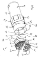
- an exploded view of the cable sleeve according to Fig. 1 can Fig. 2 be removed.
- the cable sleeve 10 of the invention is the Fig. 1 and 2 designed as a hood sleeve and has a cover designed as a cover body 11, according to Fig. 2 an interior 12 of the cable sleeve 10 is defined.
- a sealing body 14 can be inserted, wherein over the sealing body 14 on the one hand fiber optic cable in the interior 12 of the cable sleeve 10 can be inserted and on the other hand the same from the interior 12 executable.
- the seal body 14 of the cable sleeve 10 is in Fig. 3 shown in isolation, in an exploded view.
- the sealing body 14 of the cable sleeve 10 has two dimensionally stable end pieces 16 and 17, between which a compressible gel element 18 is arranged. As Fig. 2 and 3 can be removed, the sealing body 14 is formed in two parts and therefore composed of two halves 19 and 20. In the assembled state of the cable sleeve 10, the dividing plane of the sealing body 14 extends in the longitudinal direction of the cable sleeve 10 or in the longitudinal direction of the cover body 11.
- One of the two halves 19 of the seal body 14 has according to Fig. 2 and 3 formed as a snap hook projections 21 which engage in the assembled state of the seal body 14 in non-illustrated recess of the other half 20 of the seal body 14 and so hold together the two halves 19, 20 of the seal body 14.
- the cover body 11 of the cable sleeve 10 according to the invention has a stop 22, which is formed by a step-like cross-sectional change of an inner wall 23 of the cover body 11.
- the stop 22 limits the insertion depth of the seal body 14 in the interior 12 of the cover body 11, wherein when the seal body 14 rests against the stop 22 with the inner, dimensionally stable end piece 17 in an uncompressed state, the seal body 17 at least partially with the outer, dimensionally stable End piece 16 protrudes from the cover body 11 and protrudes from the same.
- a closure body 24 of the cable sleeve 10 is screwed to the outer, dimensionally stable end 16 of the seal body 14 with compression of the gel member 18, in such a way that is pressed by screwing the outer, rigid end piece 16 against the stop 22 abutting, inner end piece 17 , As Fig. 2 can be removed, the closure body 24 has for this purpose an internal thread 25, via which the closure body 24 can be screwed to an external thread 26 associated with the outer, dimensionally stable end piece 16 of the sealing body 14.
- the closure body 24 is formed, so to speak, as a union nut whose relative displaceability to the covering body 11 is limited by a stop 27, which is formed by a step-like cross-sectional change of an outer wall 28 of the covering body 11.
- the cable sleeve 10 according to the invention furthermore has at least one compensation element 29, via which the force applied by means of the closure body 24 for compressing the gel element 18 of the sealing body 14 can be stored.
- the cable sleeve 10 according to the invention has a single compensation element 29, which is designed as an elastomer ring. In the assembled state of the cable sleeve 10 formed as an elastomeric ring compensation element 29 between the inner, dimensionally stable end portion 17 of the seal body 14 and the cover body 11 formed by the stop 22 is arranged for the seal body 14.
- the compensation element 29 stores the force applied by means of the closure body 24 and permanently exerts a compression pressure on the sealing body 24 or the gel element 18 thereof. This makes it possible to compensate or compensate for a temperature-induced change in the behavior of the gel element 18 of the sealing body 14 and to ensure a good sealing effect of the sealing element 14 over a wide temperature range.
- the installation position of the seal body 14 in the cover body 11 is according to Fig. 2 Defined by the cover body 11 associated projections 30, which in slot-like recesses 31 of the seal body 14 (see Fig. 3 ) are insertable.
- the cover 11 associated with two diametrically opposed projections 30, wherein each of the projections 30 in a slot-like recess 31 of the seal body 14 is inserted.
- the slot-like recesses 31 are assigned to the outer, dimensionally stable end piece 16 of the seal body 14.
- the sealing body 14 When mounting or assembling the cable sleeve 10, therefore, the sealing body 14 is inserted into the opening 13 of the cover body 11, wherein the stop 22 of the cover 11 limits the insertion depth of the seal body 14 in the cover 11.
- the sealing body 14 is then, when the same in an uncompressed state with the inner end piece abuts against the stop 22, at least with the external thread 26 of the outer, dimensionally stable end piece 16 against the cover body 11 in front of or protrudes at least partially out of the same.
- the designed as a union nut closure body 24 is screwed with its internal thread 25 with the external thread 26 of the seal body 14, in this case due to the fact that the sealing body 14 abuts the inner end piece 17 on the stop 22, the gel element 18 of the seal body 14 is compressed.
- the compensation element 29 is also compressed, which stores the force applied to close the cable sleeve 10 via the closure body 24 and keeps the gel element 18 of the sealing body 14 permanently under a compression pressure.
- a temperature-induced change in the behavior of the gel element 18 can be compensated or compensated.
- the compensation element 29 is preferably formed from a thermoplastic elastomer, called TPE for short.
- TPE thermoplastic elastomer
- thermoplastic polyurethane short TPU or PUR suitable.
- terpolymeren elastomer such. B. from ethylene-propylene rubber, EPM for short, or called ethylene-propylene-diene rubber, EPDM short.
- EPDM ethylene-propylene-diene rubber
- the closure body 24 is open at both ends, so that the same in the sense of a union nut relative to the cover 11 can be moved.
- the openings 15 of the seal body 14, which serve the introduction or execution of optical fiber cables in the cable sleeve 10, are therefore not covered by the closure body 24.
- Another special feature of the cable sleeve 10 according to the invention is to be seen in that the inner, dimensionally stable end piece 17 of the seal body 14 adjacent to the openings 15, which serve to insert or run optical fiber cables into or out of the inner space 12 of the cable sleeve 10, web-like projections 32, which form integral Zugabfangungs shame for the optical fiber cable.
Landscapes
- Physics & Mathematics (AREA)
- General Physics & Mathematics (AREA)
- Optics & Photonics (AREA)
- Light Guides In General And Applications Therefor (AREA)
- Mechanical Coupling Of Light Guides (AREA)
- Cable Accessories (AREA)
- Braiding, Manufacturing Of Bobbin-Net Or Lace, And Manufacturing Of Nets By Knotting (AREA)
Claims (9)
- Manchon de câble pour la dépose structurée ou la manipulation de fibres optiques guidées dans des câbles à fibres optiques, notamment manchon à chapeau, comprenant un corps de recouvrement (11) définissant un espace interne (12), en particulier un chapeau de recouvrement, et un corps d'étanchéité (14) pouvant être inséré dans une ouverture (13) du corps de recouvrement (11), servant à l'introduction de câbles à fibres optiques dans l'espace interne (12) et/ou à faire ressortir des câbles à fibres optiques hors de l'espace interne (12), qui comprend deux embouts de forme stable (16, 17) et un élément de gel (18) pouvant être comprimé, disposé entre les embouts, le corps de recouvrement (11) présentant une butée (22) contre laquelle le corps d'étanchéité (14) s'applique avec un embout (17) de forme stable situé à l'intérieur, un corps de fermeture (24) pouvant être vissé avec un embout (16) de forme stable situé à l'extérieur, du corps d'étanchéité (14) par compression de l'élément de gel (18), et au moins un élément de compensation (29) accumulant la force appliquée par le biais du corps de fermeture (24) et exerçant sur l'élément de gel (18) une pression de compression permanente.
- Manchon de câble selon la revendication 1, caractérisé en ce que le ou chaque élément de compensation (29) est réalisé sous forme de bague élastomère qui est disposée entre l'embout (17) de
forme stable, situé à l'intérieur, du corps d'étanchéité (14) et la butée (22) formée par le corps de recouvrement (11). - Manchon de câble selon la revendication 1 ou 2, caractérisé en ce que le corps de fermeture (24) présente un filetage interne (25) par le biais duquel celui-ci est vissé avec un filetage externe (26) associé à l'embout (16) de forme stable, situé à l'extérieur, du corps d'étanchéité (14).
- Manchon de câble selon l'une quelconque ou plusieurs des revendications 1 à 3, caractérisé en ce que le corps de fermeture (24) est réalisé sous forme d'écrou d'accouplement.
- Manchon de câble selon l'une quelconque ou plusieurs des revendications 1 à 4, caractérisé en ce que la butée (22) est formée par une variation de section transversale de forme étagée d'une paroi intérieure (23) du corps de recouvrement (11), la butée (22) limitant la profondeur d'insertion du corps d'étanchéité (14) dans l'espace interne (12) du corps de recouvrement (11).
- Manchon de câble selon l'une quelconque ou plusieurs des revendications 1 à 5, caractérisé en ce que la position d'insertion ou la position de montage du corps d'étanchéité (14) par rapport au corps de recouvrement (11) est déterminée par au moins une saillie (30) associée au corps de recouvrement (11) et au moins un évidement (31) associé au corps d'étanchéité (14), de telle sorte que lorsque le manchon de câble est assemblé, la ou chaque saillie (30) du corps de recouvrement (11) vienne en prise dans un évidement correspondant (30) du corps d'étanchéité (14).
- Manchon de câble selon l'une quelconque ou plusieurs des revendications 1 à 6, caractérisé en ce que le corps d'étanchéité (14) est réalisé en deux parties de telle sorte qu'un plan de division de celui-ci s'étende dans la direction longitudinale du manchon de câble.
- Manchon de câble selon la revendication 7, caractérisé en ce qu'au moins une moitié (19) du corps d'étanchéité (14) est associée à au moins une saillie (21) réalisée sous forme de crochet d'encliquetage, qui vient en prise dans un état assemblé du corps d'étanchéité (14) dans un évidement de l'autre moitié respective (20) du corps d'étanchéité (14) et qui maintient ensemble ainsi les deux moitiés (19, 20) du corps d'étanchéité (14).
- Manchon de câble selon l'une quelconque ou plusieurs des revendications 1 à 8, caractérisé en ce que l'embout (17) de forme stable, situé à l'intérieur, du corps d'étanchéité (14), présente, à côté d'ouvertures (15) qui servent à insérer ou à ressortir de câbles de fibres optiques dans ou hors de l'espace interne (12) du manchon de câble (10), des saillies (32) qui forment des éléments de réception de traction intégraux pour les câbles à fibres optiques.
Applications Claiming Priority (2)
| Application Number | Priority Date | Filing Date | Title |
|---|---|---|---|
| DE202006008654U DE202006008654U1 (de) | 2006-05-30 | 2006-05-30 | Kabelmuffe zur strukturierten Ablage bzw. Handhabung von in Lichtwellenleiterkabeln geführten Lichtwellenleitern |
| PCT/EP2007/004478 WO2007137718A1 (fr) | 2006-05-30 | 2007-05-19 | Manchon de cÂble pour la dÉpose ou la manipulation structurÉe de fibres optiques passant dans des cÂbles À fibres optiques |
Publications (2)
| Publication Number | Publication Date |
|---|---|
| EP2021850A1 EP2021850A1 (fr) | 2009-02-11 |
| EP2021850B1 true EP2021850B1 (fr) | 2010-07-07 |
Family
ID=36848693
Family Applications (1)
| Application Number | Title | Priority Date | Filing Date |
|---|---|---|---|
| EP07725386A Not-in-force EP2021850B1 (fr) | 2006-05-30 | 2007-05-19 | Manchon de cable pour la depose ou la manipulation structuree de fibres optiques passant dans des cables a fibres optiques |
Country Status (6)
| Country | Link |
|---|---|
| US (1) | US8055114B2 (fr) |
| EP (1) | EP2021850B1 (fr) |
| AT (1) | ATE473462T1 (fr) |
| DE (2) | DE202006008654U1 (fr) |
| ES (1) | ES2347710T3 (fr) |
| WO (1) | WO2007137718A1 (fr) |
Cited By (1)
| Publication number | Priority date | Publication date | Assignee | Title |
|---|---|---|---|---|
| CN102540373A (zh) * | 2012-03-12 | 2012-07-04 | 南京云控通信科技有限公司 | 一种用于小规格光缆外皮紧固装置 |
Families Citing this family (17)
| Publication number | Priority date | Publication date | Assignee | Title |
|---|---|---|---|---|
| AU2001241738A1 (en) * | 2000-02-25 | 2001-09-03 | Corixa Corporation | Compounds and methods for diagnosis and immunotherapy of tuberculosis |
| WO2005088373A1 (fr) * | 2004-03-08 | 2005-09-22 | Adc Telecommunications, Inc. | Terminal d'acces de fibre optique |
| DE102008032753B4 (de) * | 2008-07-11 | 2010-05-27 | Adc Gmbh | Adapter für Muffen mit Elastomer-Kabelabdichtungen und Verfahren zur Einführung eines Lichtwellenleiterkabels in eine Muffe |
| DE202009014264U1 (de) | 2009-10-21 | 2010-01-07 | CCS Technology, Inc., Wilmington | Verteilereinrichtung für Nachrichtenkabel |
| DK2330706T3 (da) | 2009-12-03 | 2017-08-21 | CommScope Connectivity Belgium BVBA | Geletætningsenhed |
| DE202011110642U1 (de) | 2010-09-21 | 2016-03-17 | Huber + Suhner Ag | Umwelttauglich abgedichtete Kabelpeitschen-Anordnungen |
| AP2014008025A0 (en) | 2012-04-03 | 2014-10-31 | Tyco Electronics Raychem Bvba | Telecommunications enclosure and organizer |
| DK3176890T3 (da) | 2012-07-02 | 2020-05-18 | CommScope Connectivity Belgium BVBA | Kabeltætningsenhed med flere tætningsmoduler |
| DE202012013316U1 (de) * | 2012-12-18 | 2016-03-11 | Reichle & De-Massari Ag | Kabelkontaktierungswitterungsschutz |
| DE102013114533A1 (de) * | 2013-12-19 | 2015-06-25 | Reichle & De-Massari Ag | Dichtmodul |
| US10125900B2 (en) * | 2016-01-20 | 2018-11-13 | Gary Penrod | Device to prevent entry by rodents and other such pests into a recreational vehicle's service compartment |
| DE102018102295A1 (de) * | 2018-02-01 | 2019-08-01 | Reichle & De-Massari Ag | Kabelmuffenvorrichtung |
| US11837816B2 (en) * | 2018-05-31 | 2023-12-05 | Hydra-Electric Company | Method of sealing cable exit for moisture and vapor intrusion |
| WO2021152145A1 (fr) * | 2020-01-31 | 2021-08-05 | CommScope Connectivity Belgium BV | Unité d'étanchéification de câble avec plusieurs configurations |
| USD971160S1 (en) * | 2020-09-04 | 2022-11-29 | Juice Technology AG | Female electric vehicle charging connector |
| USD971159S1 (en) * | 2020-09-04 | 2022-11-29 | Juice Technology AG | Male electric vehicle charging connector |
| CN114964027B (zh) * | 2022-04-29 | 2025-04-01 | 太原理工大学 | 一种边坡测斜管变形监测系统 |
Family Cites Families (52)
| Publication number | Priority date | Publication date | Assignee | Title |
|---|---|---|---|---|
| US3848074A (en) * | 1973-04-13 | 1974-11-12 | W Channell | Terminal and splice enclosure for cable installations |
| DE3726718A1 (de) | 1986-04-07 | 1989-02-23 | Siemens Ag | Vorrichtung zum anbringen einer mechanischen verbindung am kabelmantel eines optischen kabels |
| DE3726719A1 (de) | 1986-04-07 | 1989-02-23 | Siemens Ag | Vorrichtung zum anbringen einer mechanischen verbindung am kabelmantel eines optischen kabels |
| US5055636A (en) * | 1990-05-31 | 1991-10-08 | Reliance Comm/Tec Corporation | Sealed reenterable splice enclosure |
| US5097529A (en) | 1991-03-22 | 1992-03-17 | At&T Bell Laboratories | Space-saving optical fiber cable closure |
| EP0587621A1 (fr) | 1991-06-06 | 1994-03-23 | N.V. Raychem S.A. | Dispositif d'etancheite pour cables |
| GB9112181D0 (en) | 1991-06-06 | 1991-07-24 | Raychem Sa Nv | Cable sealing |
| GB9212625D0 (en) | 1992-06-15 | 1992-07-29 | Raychem Sa Nv | Cable sealing device |
| GB9212624D0 (en) | 1992-06-15 | 1992-07-29 | Raychem Sa Nv | Cable sealing device |
| DE4231181C1 (en) | 1992-09-17 | 1993-08-26 | Siemens Ag, 8000 Muenchen, De | Cable restraint for fibre=optic cable distribution box - comprises U=shaped fixing shell fastened to rail which mounts screw for fixing cable central strain element |
| US5479554A (en) | 1994-01-11 | 1995-12-26 | Windsor Communications | Splice closure apparatus for continuous optical ground wire communications cable and splicing system |
| US5446823A (en) | 1994-01-26 | 1995-08-29 | Raychem Corporation | Aerial, pedestal, below grade, or buried optical fiber closure |
| GB9404396D0 (en) * | 1994-03-07 | 1994-04-20 | Raychem Sa Nv | Sealing arrangement |
| GB9405535D0 (en) | 1994-03-21 | 1994-05-04 | Raychem Sa Nv | Splice organizing apparatus |
| ATE187256T1 (de) | 1994-07-21 | 1999-12-15 | Rxs Schrumpftech Garnituren | Abfangsvorrichtung für optische kabel |
| US5793921A (en) | 1995-03-20 | 1998-08-11 | Psi Telecommunications, Inc. | Kit and method for converting a conductive cable closure to a fiber optic cable closure |
| TW286371B (fr) | 1995-03-31 | 1996-09-21 | Minnesota Mining & Mfg | |
| NZ303594A (en) | 1995-03-31 | 1999-01-28 | Minnesota Mining & Mfg | Optical fibre splice tray arrangement |
| US5617501A (en) | 1995-03-31 | 1997-04-01 | Minnesota Mining And Manufacturing Company | Shield bond strain connector for fiber optic closure |
| KR100418847B1 (ko) | 1995-04-12 | 2004-04-21 | 에르익스에스 게젤샤프트 푀르퍼뫼겐스퍼발퉁 엠바하 | 후드슬리브 |
| DE69637538D1 (fr) | 1995-09-29 | 2008-07-03 | Minnesota Mining & Mfg | |
| US5598499A (en) * | 1995-11-01 | 1997-01-28 | Lucent Technologies, Inc. | Seal for cable splice closure |
| US5652820A (en) | 1995-11-13 | 1997-07-29 | Act Communications, Inc. | Fiber optic splice closure and protection apparatus |
| FR2748867B1 (fr) | 1996-05-15 | 1998-06-19 | Alcatel Cable Interface | Dispositif d'etancheite de cables dans un acces |
| GB9617591D0 (en) | 1996-08-22 | 1996-10-02 | Raychem Sa Nv | Optical fibre splice closure |
| DE19645846A1 (de) | 1996-11-07 | 1998-05-14 | Psi Products Gmbh | Bausatz zur Erzeugung einer Muffe für Verteilernetze der Telekommunikation od.dgl. |
| US5774618A (en) | 1996-12-19 | 1998-06-30 | Lucent Technologies Inc. | Compact closure for optical fiber cable |
| DE19728370A1 (de) | 1997-07-03 | 1999-01-07 | Bosch Gmbh Robert | Kabeldurchführung für Anschlußkabel eines Gasmeßfühlers |
| AU9732998A (en) | 1997-12-22 | 1999-07-12 | Huber & Suhner Ag | Cable sleeve |
| GB9805965D0 (en) * | 1998-03-21 | 1998-05-20 | Cannon Telecomms Limited | Single-ended joint cable sealing system |
| CA2327704A1 (fr) * | 1998-04-28 | 1999-11-04 | Dirk Deroost | Boitier |
| US6175083B1 (en) | 1998-12-11 | 2001-01-16 | Caterpillar Inc. | Sealing a lead from a confined cavity of an apparatus |
| US6321021B1 (en) * | 1999-07-12 | 2001-11-20 | Ocean Design, Inc. | End seal assembly for tubular conduit |
| US6411767B1 (en) | 1999-08-24 | 2002-06-25 | Corning Cable Systems Llc | Optical fiber interconnection closures |
| US6292614B1 (en) | 1999-08-24 | 2001-09-18 | Siecor Operations, Llc | Movable bracket for holding internal components of an optical fiber interconnection closure during servicing and associated method |
| US6315461B1 (en) * | 1999-10-14 | 2001-11-13 | Ocean Design, Inc. | Wet mateable connector |
| US6533472B1 (en) | 1999-10-19 | 2003-03-18 | Alcoa Fujikura Limited | Optical fiber splice closure assembly |
| CN1311600C (zh) | 1999-12-02 | 2007-04-18 | Ccs技术公司 | 用于纵向分体电缆配件的密封体 |
| DE10010452A1 (de) | 1999-12-02 | 2001-06-07 | Rxs Kabelgarnituren Gmbh & Co | Dichtungskörper für längsgeteilte Kabelgarnituren |
| AU2002213249A1 (en) * | 2000-10-17 | 2002-04-29 | Preformed Line Products Company | Cable closure and assembly |
| US6628880B2 (en) | 2001-04-06 | 2003-09-30 | Windsor Communications, Inc. | Fiber optic cable splice enclosure |
| CN1307444C (zh) | 2001-05-25 | 2007-03-28 | 预制管线产品公司 | 光纤电缆罩和组件 |
| DE10338848A1 (de) | 2003-08-20 | 2005-03-17 | CCS Technology, Inc., Wilmington | Abfangvorrichtung für optische Kabel, Kabelmuffe mit einer solchen Abfangvorrichtung und Verfahren zur Bereitstellung einer Abfangung für optische Kabel unter Verwendung einer solchen Abfangvorrichtung |
| DE202005009932U1 (de) | 2005-06-22 | 2005-11-24 | CCS Technology, Inc., Wilmington | Vorrichtung zur Abfangung von in Mikroducts geführten Mikrokabeln sowie der Mikroducts |
| US8422835B2 (en) * | 2005-06-30 | 2013-04-16 | Weatherford/Lamb, Inc. | Optical waveguide feedthrough assembly |
| US7045710B1 (en) | 2005-08-31 | 2006-05-16 | 3M Innovative Properties Company | Enclosure for telecommunication lines and splices |
| DE202005014677U1 (de) | 2005-09-16 | 2005-11-17 | CCS Technology, Inc., Wilmington | Vorrichtung zur Abfangung von Kabeln |
| US7308183B2 (en) | 2006-01-04 | 2007-12-11 | Adc Telecommunications, Inc. | Fiber access terminal including moisture barrier plate |
| US7330628B1 (en) | 2006-10-23 | 2008-02-12 | Adc Telecommunications, Inc. | Fiber access terminal including moisture barrier plate with punch out |
| DE102007010853B4 (de) | 2007-03-01 | 2009-01-29 | Adc Gmbh | Verteilereinrichtung für Lichtwellenleiter |
| DE102007010854B4 (de) | 2007-03-01 | 2009-01-08 | Adc Gmbh | Konsole für eine Verteilereinrichtung für Lichtwellenleiter-Kabel |
| DE102007010863B4 (de) | 2007-03-01 | 2009-01-08 | Adc Gmbh | Muffe für Lichtwellenleiter-Kabel |
-
2006
- 2006-05-30 DE DE202006008654U patent/DE202006008654U1/de not_active Expired - Lifetime
-
2007
- 2007-05-19 DE DE502007004334T patent/DE502007004334D1/de active Active
- 2007-05-19 WO PCT/EP2007/004478 patent/WO2007137718A1/fr not_active Ceased
- 2007-05-19 AT AT07725386T patent/ATE473462T1/de active
- 2007-05-19 EP EP07725386A patent/EP2021850B1/fr not_active Not-in-force
- 2007-05-19 ES ES07725386T patent/ES2347710T3/es active Active
-
2008
- 2008-11-26 US US12/323,530 patent/US8055114B2/en active Active
Cited By (2)
| Publication number | Priority date | Publication date | Assignee | Title |
|---|---|---|---|---|
| CN102540373A (zh) * | 2012-03-12 | 2012-07-04 | 南京云控通信科技有限公司 | 一种用于小规格光缆外皮紧固装置 |
| CN102540373B (zh) * | 2012-03-12 | 2014-03-05 | 南京云控通信科技有限公司 | 一种用于小规格光缆外皮紧固装置 |
Also Published As
| Publication number | Publication date |
|---|---|
| US20090103876A1 (en) | 2009-04-23 |
| DE202006008654U1 (de) | 2006-08-03 |
| WO2007137718A1 (fr) | 2007-12-06 |
| ATE473462T1 (de) | 2010-07-15 |
| US8055114B2 (en) | 2011-11-08 |
| DE502007004334D1 (de) | 2010-08-19 |
| ES2347710T3 (es) | 2010-11-03 |
| EP2021850A1 (fr) | 2009-02-11 |
Similar Documents
| Publication | Publication Date | Title |
|---|---|---|
| EP2021850B1 (fr) | Manchon de cable pour la depose ou la manipulation structuree de fibres optiques passant dans des cables a fibres optiques | |
| EP2021849A1 (fr) | Manchon de cable pour la depose ou la manipulation structuree de fibres optiques passant dans des cables a fibres optiques | |
| EP2005230B1 (fr) | Corps d'étanchéité d'un manchon de câble | |
| DE69503483T2 (de) | Abdichtungsanordnung | |
| DE69215269T2 (de) | Kabelverschlussvorrichtung mit einer verbesserten Dichtungsbuchse | |
| DE202006006019U1 (de) | Dichtungskörper einer Kabelmuffe | |
| EP2385599B1 (fr) | Jonction de câbles en ligne | |
| EP2251729B1 (fr) | Boîtier de cable avec dispositif de scellement | |
| WO2014095462A1 (fr) | Dispositif de protection contre les intempéries d'une mise en contact électrique de câble | |
| EP3726267B1 (fr) | Joint de tube individuel et tube en matière plastique | |
| DE102012105067A1 (de) | Kabelrohrdichtungsvorrichtung | |
| DE102006046488B4 (de) | Abgedichteter elektrischer Anschluss eines Gehäuses einer elektrischen Steuereinheit und Hydraulikmaschine mit einem Gehäuse mit einem derartigen Anschluss | |
| DE202007014971U1 (de) | Kabelmuffe | |
| CH714248B1 (de) | Mehrteiliges Gehäuse für Verbrauchszähler sowie Sicherungseinrichtung für mehrteilige Gehäuse. | |
| EP2057495B1 (fr) | Manchon de câbles | |
| DE10021882B4 (de) | LWL-Klemme | |
| DE3329904C2 (fr) | ||
| DE20308264U1 (de) | Lichtwellenleiter-Steckverbindung | |
| DE102005014373B3 (de) | Elektrische Steckvorrichtung | |
| EP2054747B1 (fr) | Manchon de câbles | |
| DE19947207A1 (de) | Dichtungselement und Verfahren zur Herstellung | |
| DE102008063192A1 (de) | Kabeldurchführung zur Durchführung eines Kabels durch eine Gehäusewand | |
| DE202015106891U1 (de) | Kabeldurchführung, insbesondere für ein elektronisches Gerät | |
| DE102020115040A1 (de) | Leitungsdurchführungsvorrichtung |
Legal Events
| Date | Code | Title | Description |
|---|---|---|---|
| PUAI | Public reference made under article 153(3) epc to a published international application that has entered the european phase |
Free format text: ORIGINAL CODE: 0009012 |
|
| 17P | Request for examination filed |
Effective date: 20081105 |
|
| AK | Designated contracting states |
Kind code of ref document: A1 Designated state(s): AT BE BG CH CY CZ DE DK EE ES FI FR GB GR HU IE IS IT LI LT LU LV MC MT NL PL PT RO SE SI SK TR |
|
| AX | Request for extension of the european patent |
Extension state: AL BA HR MK RS |
|
| GRAP | Despatch of communication of intention to grant a patent |
Free format text: ORIGINAL CODE: EPIDOSNIGR1 |
|
| GRAS | Grant fee paid |
Free format text: ORIGINAL CODE: EPIDOSNIGR3 |
|
| GRAA | (expected) grant |
Free format text: ORIGINAL CODE: 0009210 |
|
| AK | Designated contracting states |
Kind code of ref document: B1 Designated state(s): AT BE BG CH CY CZ DE DK EE ES FI FR GB GR HU IE IS IT LI LT LU LV MC MT NL PL PT RO SE SI SK TR |
|
| REG | Reference to a national code |
Ref country code: GB Ref legal event code: FG4D Free format text: NOT ENGLISH |
|
| REG | Reference to a national code |
Ref country code: CH Ref legal event code: EP |
|
| REG | Reference to a national code |
Ref country code: IE Ref legal event code: FG4D |
|
| REF | Corresponds to: |
Ref document number: 502007004334 Country of ref document: DE Date of ref document: 20100819 Kind code of ref document: P |
|
| REG | Reference to a national code |
Ref country code: NL Ref legal event code: VDEP Effective date: 20100707 |
|
| REG | Reference to a national code |
Ref country code: ES Ref legal event code: FG2A Ref document number: 2347710 Country of ref document: ES Kind code of ref document: T3 |
|
| PG25 | Lapsed in a contracting state [announced via postgrant information from national office to epo] |
Ref country code: SI Free format text: LAPSE BECAUSE OF FAILURE TO SUBMIT A TRANSLATION OF THE DESCRIPTION OR TO PAY THE FEE WITHIN THE PRESCRIBED TIME-LIMIT Effective date: 20100707 |
|
| LTIE | Lt: invalidation of european patent or patent extension |
Effective date: 20100707 |
|
| PG25 | Lapsed in a contracting state [announced via postgrant information from national office to epo] |
Ref country code: NL Free format text: LAPSE BECAUSE OF FAILURE TO SUBMIT A TRANSLATION OF THE DESCRIPTION OR TO PAY THE FEE WITHIN THE PRESCRIBED TIME-LIMIT Effective date: 20100707 Ref country code: FI Free format text: LAPSE BECAUSE OF FAILURE TO SUBMIT A TRANSLATION OF THE DESCRIPTION OR TO PAY THE FEE WITHIN THE PRESCRIBED TIME-LIMIT Effective date: 20100707 Ref country code: LT Free format text: LAPSE BECAUSE OF FAILURE TO SUBMIT A TRANSLATION OF THE DESCRIPTION OR TO PAY THE FEE WITHIN THE PRESCRIBED TIME-LIMIT Effective date: 20100707 |
|
| REG | Reference to a national code |
Ref country code: IE Ref legal event code: FD4D |
|
| PG25 | Lapsed in a contracting state [announced via postgrant information from national office to epo] |
Ref country code: IS Free format text: LAPSE BECAUSE OF FAILURE TO SUBMIT A TRANSLATION OF THE DESCRIPTION OR TO PAY THE FEE WITHIN THE PRESCRIBED TIME-LIMIT Effective date: 20101107 Ref country code: PT Free format text: LAPSE BECAUSE OF FAILURE TO SUBMIT A TRANSLATION OF THE DESCRIPTION OR TO PAY THE FEE WITHIN THE PRESCRIBED TIME-LIMIT Effective date: 20101108 Ref country code: BG Free format text: LAPSE BECAUSE OF FAILURE TO SUBMIT A TRANSLATION OF THE DESCRIPTION OR TO PAY THE FEE WITHIN THE PRESCRIBED TIME-LIMIT Effective date: 20101007 Ref country code: PL Free format text: LAPSE BECAUSE OF FAILURE TO SUBMIT A TRANSLATION OF THE DESCRIPTION OR TO PAY THE FEE WITHIN THE PRESCRIBED TIME-LIMIT Effective date: 20100707 Ref country code: CY Free format text: LAPSE BECAUSE OF FAILURE TO SUBMIT A TRANSLATION OF THE DESCRIPTION OR TO PAY THE FEE WITHIN THE PRESCRIBED TIME-LIMIT Effective date: 20100707 |
|
| PG25 | Lapsed in a contracting state [announced via postgrant information from national office to epo] |
Ref country code: LV Free format text: LAPSE BECAUSE OF FAILURE TO SUBMIT A TRANSLATION OF THE DESCRIPTION OR TO PAY THE FEE WITHIN THE PRESCRIBED TIME-LIMIT Effective date: 20100707 Ref country code: SE Free format text: LAPSE BECAUSE OF FAILURE TO SUBMIT A TRANSLATION OF THE DESCRIPTION OR TO PAY THE FEE WITHIN THE PRESCRIBED TIME-LIMIT Effective date: 20100707 Ref country code: GR Free format text: LAPSE BECAUSE OF FAILURE TO SUBMIT A TRANSLATION OF THE DESCRIPTION OR TO PAY THE FEE WITHIN THE PRESCRIBED TIME-LIMIT Effective date: 20101008 |
|
| PG25 | Lapsed in a contracting state [announced via postgrant information from national office to epo] |
Ref country code: IE Free format text: LAPSE BECAUSE OF FAILURE TO SUBMIT A TRANSLATION OF THE DESCRIPTION OR TO PAY THE FEE WITHIN THE PRESCRIBED TIME-LIMIT Effective date: 20100707 Ref country code: DK Free format text: LAPSE BECAUSE OF FAILURE TO SUBMIT A TRANSLATION OF THE DESCRIPTION OR TO PAY THE FEE WITHIN THE PRESCRIBED TIME-LIMIT Effective date: 20100707 |
|
| PLBE | No opposition filed within time limit |
Free format text: ORIGINAL CODE: 0009261 |
|
| STAA | Information on the status of an ep patent application or granted ep patent |
Free format text: STATUS: NO OPPOSITION FILED WITHIN TIME LIMIT |
|
| PG25 | Lapsed in a contracting state [announced via postgrant information from national office to epo] |
Ref country code: RO Free format text: LAPSE BECAUSE OF FAILURE TO SUBMIT A TRANSLATION OF THE DESCRIPTION OR TO PAY THE FEE WITHIN THE PRESCRIBED TIME-LIMIT Effective date: 20100707 Ref country code: SK Free format text: LAPSE BECAUSE OF FAILURE TO SUBMIT A TRANSLATION OF THE DESCRIPTION OR TO PAY THE FEE WITHIN THE PRESCRIBED TIME-LIMIT Effective date: 20100707 Ref country code: CZ Free format text: LAPSE BECAUSE OF FAILURE TO SUBMIT A TRANSLATION OF THE DESCRIPTION OR TO PAY THE FEE WITHIN THE PRESCRIBED TIME-LIMIT Effective date: 20100707 Ref country code: EE Free format text: LAPSE BECAUSE OF FAILURE TO SUBMIT A TRANSLATION OF THE DESCRIPTION OR TO PAY THE FEE WITHIN THE PRESCRIBED TIME-LIMIT Effective date: 20100707 |
|
| 26N | No opposition filed |
Effective date: 20110408 |
|
| REG | Reference to a national code |
Ref country code: DE Ref legal event code: R097 Ref document number: 502007004334 Country of ref document: DE Effective date: 20110408 |
|
| PG25 | Lapsed in a contracting state [announced via postgrant information from national office to epo] |
Ref country code: MT Free format text: LAPSE BECAUSE OF FAILURE TO SUBMIT A TRANSLATION OF THE DESCRIPTION OR TO PAY THE FEE WITHIN THE PRESCRIBED TIME-LIMIT Effective date: 20100707 Ref country code: MC Free format text: LAPSE BECAUSE OF NON-PAYMENT OF DUE FEES Effective date: 20110531 |
|
| REG | Reference to a national code |
Ref country code: CH Ref legal event code: PL |
|
| PG25 | Lapsed in a contracting state [announced via postgrant information from national office to epo] |
Ref country code: LI Free format text: LAPSE BECAUSE OF NON-PAYMENT OF DUE FEES Effective date: 20110531 Ref country code: CH Free format text: LAPSE BECAUSE OF NON-PAYMENT OF DUE FEES Effective date: 20110531 |
|
| PG25 | Lapsed in a contracting state [announced via postgrant information from national office to epo] |
Ref country code: LU Free format text: LAPSE BECAUSE OF NON-PAYMENT OF DUE FEES Effective date: 20110519 |
|
| REG | Reference to a national code |
Ref country code: AT Ref legal event code: MM01 Ref document number: 473462 Country of ref document: AT Kind code of ref document: T Effective date: 20120519 |
|
| PG25 | Lapsed in a contracting state [announced via postgrant information from national office to epo] |
Ref country code: AT Free format text: LAPSE BECAUSE OF NON-PAYMENT OF DUE FEES Effective date: 20120519 |
|
| PG25 | Lapsed in a contracting state [announced via postgrant information from national office to epo] |
Ref country code: TR Free format text: LAPSE BECAUSE OF FAILURE TO SUBMIT A TRANSLATION OF THE DESCRIPTION OR TO PAY THE FEE WITHIN THE PRESCRIBED TIME-LIMIT Effective date: 20100707 |
|
| PG25 | Lapsed in a contracting state [announced via postgrant information from national office to epo] |
Ref country code: HU Free format text: LAPSE BECAUSE OF FAILURE TO SUBMIT A TRANSLATION OF THE DESCRIPTION OR TO PAY THE FEE WITHIN THE PRESCRIBED TIME-LIMIT Effective date: 20100707 |
|
| REG | Reference to a national code |
Ref country code: FR Ref legal event code: PLFP Year of fee payment: 10 |
|
| REG | Reference to a national code |
Ref country code: FR Ref legal event code: PLFP Year of fee payment: 11 |
|
| REG | Reference to a national code |
Ref country code: FR Ref legal event code: PLFP Year of fee payment: 12 |
|
| PGFP | Annual fee paid to national office [announced via postgrant information from national office to epo] |
Ref country code: BE Payment date: 20200421 Year of fee payment: 14 |
|
| REG | Reference to a national code |
Ref country code: BE Ref legal event code: MM Effective date: 20210531 |
|
| PG25 | Lapsed in a contracting state [announced via postgrant information from national office to epo] |
Ref country code: BE Free format text: LAPSE BECAUSE OF NON-PAYMENT OF DUE FEES Effective date: 20210531 |
|
| REG | Reference to a national code |
Ref country code: FR Ref legal event code: PLFP Year of fee payment: 17 |
|
| PGFP | Annual fee paid to national office [announced via postgrant information from national office to epo] |
Ref country code: IT Payment date: 20230510 Year of fee payment: 17 Ref country code: FR Payment date: 20230412 Year of fee payment: 17 Ref country code: ES Payment date: 20230608 Year of fee payment: 17 Ref country code: DE Payment date: 20230412 Year of fee payment: 17 |
|
| PGFP | Annual fee paid to national office [announced via postgrant information from national office to epo] |
Ref country code: GB Payment date: 20230412 Year of fee payment: 17 |
|
| REG | Reference to a national code |
Ref country code: DE Ref legal event code: R119 Ref document number: 502007004334 Country of ref document: DE |
|
| GBPC | Gb: european patent ceased through non-payment of renewal fee |
Effective date: 20240519 |
|
| PG25 | Lapsed in a contracting state [announced via postgrant information from national office to epo] |
Ref country code: DE Free format text: LAPSE BECAUSE OF NON-PAYMENT OF DUE FEES Effective date: 20241203 |
|
| PG25 | Lapsed in a contracting state [announced via postgrant information from national office to epo] |
Ref country code: FR Free format text: LAPSE BECAUSE OF NON-PAYMENT OF DUE FEES Effective date: 20240531 |
|
| PG25 | Lapsed in a contracting state [announced via postgrant information from national office to epo] |
Ref country code: GB Free format text: LAPSE BECAUSE OF NON-PAYMENT OF DUE FEES Effective date: 20240519 Ref country code: IT Free format text: LAPSE BECAUSE OF NON-PAYMENT OF DUE FEES Effective date: 20240519 |
|
| REG | Reference to a national code |
Ref country code: ES Ref legal event code: FD2A Effective date: 20250703 |
|
| PG25 | Lapsed in a contracting state [announced via postgrant information from national office to epo] |
Ref country code: ES Free format text: LAPSE BECAUSE OF NON-PAYMENT OF DUE FEES Effective date: 20240520 |