EP2022708A2 - Schlafliegen-Rahmen für Schlafliegen von Fahrerhäusern von Nutzfahrzeugen - Google Patents
Schlafliegen-Rahmen für Schlafliegen von Fahrerhäusern von Nutzfahrzeugen Download PDFInfo
- Publication number
- EP2022708A2 EP2022708A2 EP08012433A EP08012433A EP2022708A2 EP 2022708 A2 EP2022708 A2 EP 2022708A2 EP 08012433 A EP08012433 A EP 08012433A EP 08012433 A EP08012433 A EP 08012433A EP 2022708 A2 EP2022708 A2 EP 2022708A2
- Authority
- EP
- European Patent Office
- Prior art keywords
- frame
- parts
- frame according
- slatted
- functional elements
- Prior art date
- Legal status (The legal status is an assumption and is not a legal conclusion. Google has not performed a legal analysis and makes no representation as to the accuracy of the status listed.)
- Granted
Links
Images

Classifications
-
- B—PERFORMING OPERATIONS; TRANSPORTING
- B62—LAND VEHICLES FOR TRAVELLING OTHERWISE THAN ON RAILS
- B62D—MOTOR VEHICLES; TRAILERS
- B62D33/00—Superstructures for load-carrying vehicles
- B62D33/06—Drivers' cabs
- B62D33/0612—Cabins with living accommodation, especially for long distance road vehicles, i.e. sleeping, cooking, or other facilities
-
- B—PERFORMING OPERATIONS; TRANSPORTING
- B60—VEHICLES IN GENERAL
- B60P—VEHICLES ADAPTED FOR LOAD TRANSPORTATION OR TO TRANSPORT, TO CARRY, OR TO COMPRISE SPECIAL LOADS OR OBJECTS
- B60P3/00—Vehicles adapted to transport, to carry or to comprise special loads or objects
- B60P3/32—Vehicles adapted to transport, to carry or to comprise special loads or objects comprising living accommodation for people, e.g. caravans, camping, or like vehicles
- B60P3/36—Auxiliary arrangements; Arrangements of living accommodation; Details
- B60P3/38—Sleeping arrangements, e.g. living or sleeping accommodation on the roof of the vehicle
Definitions
- the invention relates to a sleeping-bed frame of cabs of commercial vehicles, in particular of trucks, according to the preamble of claim 1.
- the sleeping loungers In long-distance cabs, up to two sleeping loungers can be installed. These sleeping loungers are usually arranged one above the other behind the seats. Both the lower and the upper bunk can be designed to be folded up. As a rule, the sleeping loungers consist of a support frame or bed frame with a slatted frame as a base and a mattress resting on the slatted frame. For different models of vehicles also different types or sizes of sleeping loungers are regularly required, which also, in contrast to conventional beds, greater functionality or secure fix the sleeping berth in the cab is required, which makes a variety of other components or functional elements required to provide a high quality sleeping berth.
- the sleeping-bed frame is constructed in several parts from individual frame parts that can be connected to each other, in particular detachably connected.
- Such a multi-part allows a flexible and less component-intensive adaptation of a frame to different cab conditions.
- integration of functional elements in certain frame parts advantageously standardized frame parts are provided, for. B. in the form of holders and / or Aufsteckelementen and / or connection points and / or bearing elements or the like, as they are required for almost all sleep table designs.
- certain frame parts in particular frame side parts of a frame having a rectangular shape, which are connected to frame longitudinal parts can be provided, which can be used in a plurality of different cabs, so that z. B. for length adjustment only the other frame parts, in particular the frame longitudinal parts must be kept in different sizes.
- functional parts having frame parts, in particular functional elements having frame side parts of different types can be kept in which z. B. different of the aforementioned functional elements are integrated to form a set of arbitrarily combinable frame parts, so that a simple and individual adaptation to the respective cab conditions is possible in a simple manner.
- the frame side parts can be connected to the frame longitudinal parts by means of a plug connection.
- a plug connection can be produced in a simple manner a functionally reliable connection of the different frame parts.
- the plug-in connection is formed by a frame side part side plug-in pin, which can be positively inserted into a frame longitudinal part side plug receptacle as another component of the connector.
- this connector may further be provided that this is fixed by means of an additional safety device, in particular by means of a locking screw and / or by means of a Sich ceremoniesssplintes.
- the fixation can here z. B. specifically be formed by a transverse to the direction of insertion through the spigot and the pin receiving plug inserted locking screw or Sich ceremoniesssplint.
- the frame parts not having functional elements are formed by manufacturing technology simple and inexpensive extruded profiles, in particular by light metal extruded profiles.
- the frame parts are formed by manufacturing technology simple and inexpensive extruded profiles, in particular by light metal extruded profiles.
- an extruded profile as a frame part can be realized in a simple and inexpensive way different configurations and shapes of the frame profiles.
- the frame parts having the functional elements are designed as cast components, preferably as die-cast components.
- the functional elements are designed as cast components, preferably as die-cast components.
- preferred material is again a light metal. Basically, the use of plastic is possible.
- frame parts by extruded profiles or by cast components is based on the general idea that those frame parts that have no integral integrally formed functional elements are to be produced in a simple and inexpensive manner by extrusion, while the functional elements integrally having frame parts, however, in contrast something more complex casting method, in particular die-casting process to be produced, since the function integration is possible in a simple and inexpensive manner by means of such a casting process.
- the frame is positive and / or non-positive, as already mentioned, connected to a slatted frame, on which in turn a mattress is placed.
- This mattress can then be positively and / or non-positively connected to the frame and / or the slatted frame.
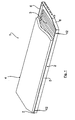
- a bunk 1 which has a frame 2, in which a slatted frame 3 is inserted. Furthermore, a mattress 4 is used in frame 2. All components are preferably connected to each other positively and / or non-positively.
- the frame 2 of the invention consists of several parts of interconnectable frame parts, namely two to form a rectangular shape of the frame 2 parallel to each other and a predetermined distance having frame longitudinal members 5, 6 and two of the frame longitudinal parts 5, 6 subsequent frame side parts. 7 , 8, which form the front side parts in the present example case.
- the two frame longitudinal parts 5, 6 have an equal length and are produced by injection molding profile parts, preferably made of light metal.
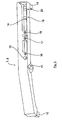
- the two frame side parts 7, 8 are, however, as this particular from Fig. 3 shows, formed as a die-cast parts, which have a number of functional elements described in more detail below in an integral manner.
- the frame side parts 7, 8 are each connected by means of two connectors 9 with the frame members 5, 6. Specifically, this is on the frame side parts 7, 8 each end a plug-in pin 10 is formed in the in Fig. 1 shown assembled state positively engages in a plug-pin receptacle 11 which is formed at the two end portions of the frame longitudinal members 5, 6.
- a screw 12 is shown schematically in the Fig. 1 located.
- the frame side parts 7, 8 which are preferably designed as common parts, functional elements in the die casting process, here, for example, through holes or Anschraubpositionen 13, 14 for the slatted base 3, a bearing pin 15 for a front bedding storage, connection points 16, 17, 18 for gas springs and screw points 19, 20 of the bunk on a rear couchette.
Landscapes
- Engineering & Computer Science (AREA)
- Transportation (AREA)
- Mechanical Engineering (AREA)
- Chemical & Material Sciences (AREA)
- Combustion & Propulsion (AREA)
- Health & Medical Sciences (AREA)
- Public Health (AREA)
- Seats For Vehicles (AREA)
- Body Structure For Vehicles (AREA)
- Mattresses And Other Support Structures For Chairs And Beds (AREA)
Abstract
Description
- Die Erfindung betrifft einen Schlafliegen-Rahmen von Fahrerhäusern von Nutzfahrzeugen, insbesondere von Lastkraftwagen, nach dem Oberbegriff des Anspruchs 1.
- In Fernverkehr-Fahrerhäusern können bis zu zwei Schlafliegen eingebaut werden. Diese Schlafliegen werden in der Regel hinter den Sitzen übereinander angeordnet. Sowohl die untere als auch die obere Schlafliege können hochklappbar ausgeführt sein. Die Schlafliegen bestehen im Regelfall aus einem Tragrahmen bzw. Bettrahmen mit einem Lattenrost als Unterfederung sowie einer auf dem Lattenrost aufliegenden Matratze. Für unterschiedliche Modelle von Fahrzeugen werden regelmäßig auch unterschiedliche Arten bzw. Größen von Schlafliegen benötigt, wobei zudem, im Gegensatz zu herkömmlichen Betten, eine größere Funktionalität bzw. sichere Fixierung der Schlafliege im Fahrerhaus erforderlich ist, was eine Vielzahl weiterer Bauteile bzw. Funktionselemente erforderlich macht, um eine qualitativ hochwertige Schlafliege zur Verfügung zu stellen.
- Für unterschiedliche Fahrerhäuser von Nutzfahrzeugen sind somit regelmäßig eine Vielzahl von unterschiedlichen Schlafliegen vorzuhalten.
- Es ist daher Aufgabe der vorliegenden Erfindung, einen Schlafliegen-Rahmen für Schlafliegen von Fahrerhäusern von Nutzfahrzeugen, insbesondere von Lastkraftwagen, zur Verfügung zu stellen, der auf baulich und herstellungstechnisch einfache Weise an unterschiedliche Fahrerhausgegebenheiten von Nutzfahrzeugen anpassbar ist.
- Diese Aufgabe wird gelöst mit den Merkmalen des Anspruchs 1. Vorteilhafte Ausgestaltungen der Erfindung sind Gegenstand der Unteransprüche.
- Erfindungsgemäß ist vorgesehen, dass der Schlafliegen-Rahmen mehrteilig aus einzelnen miteinander verbindbaren, insbesondere lösbar verbindbaren Rahmenteilen aufgebaut ist. Eine derartige Mehrteiligkeit erlaubt eine flexible und wenig bauteilintensive Anpassung eines Rahmens an unterschiedliche Fahrerhausgegebenheiten. So können insbesondere in Verbindung mit der gemäß einer besonders bevorzugten Ausgestaltung der vorliegenden Erfindung vorgesehenen Integration von Funktionselementen in bestimmte Rahmenteile vorteilhaft standardisierte Rahmenteile zur Verfügung gestellt werden, z. B. in Form von Haltern und/oder Aufsteckelementen und/oder Anbindungspunkten und/oder Lagerelementen oder dergleichen, wie sie für nahezu alle Schlafliegenausbildungen erforderlich sind. Dadurch können bestimmte Rahmenteile, insbesondere Rahmenseitenteile eines eine Rechteckform aufweisenden Rahmens, die an Rahmenlängsteile anschließen, zur Verfügung gestellt werden, die in einer Vielzahl von unterschiedlichen Fahrerhäusern verwendet werden können, so dass z. B. zur Längenanpassung lediglich die anderen Rahmenteile, insbesondere die Rahmenlängsteile in unterschiedlicher Größe vorgehalten werden müssen. Grundsätzlich können jedoch auch Funktionselemente aufweisende Rahmenteile, insbesondere Funktionselemente aufweisende Rahmenseitenteile unterschiedlicher Art vorgehalten werden, in denen z. B. unterschiedliche der zuvor genannten Funktionselemente integriert sind, um ein Set von beliebig miteinander kombinierbaren Rahmenteilen auszubilden, so dass eine einfache und individuelle Anpassung an die jeweiligen Fahrerhausgegebenheiten auf einfache Weise möglich ist.
- Gemäß einer weiteren besonders bevorzugten Ausgestaltung der vorliegenden Erfindung ist vorgesehen, dass die Rahmenseitenteile mit den Rahmenlängsteilen mittels einer Steckverbindung verbindbar sind. Mit einer derartigen Steckverbindung lässt sich auf einfache Weise eine funktionssichere Verbindung der unterschiedlichen Rahmenteile herstellen. Gemäß einer bevorzugten konkreten Ausführungsform ist die Steckverbindung durch einen rahmenseitenteilseitigen Steckzapfen ausgebildet, der formschlüssig in eine rahmenlängsteilseitige Steckzapfenaufnahme als weiteren Bestandteil der Steckverbindung eingesteckt werden kann. Zur sicheren Fixierung dieser Steckverbindung kann ferner vorgesehen sein, dass diese mittels einer zusätzlichen Sicherheitseinrichtung, insbesondere mittels einer Sicherungsschraube und/oder mittels eines Sicherungssplintes, fixiert ist. Die Fixierung kann hier z. B. konkret durch eine quer zur Steckrichtung durch den Steckzapfen und die Steckzapfenaufnahme gesteckte Sicherungsschraube oder Sicherungssplint gebildet sein.
- Gemäß einer besonders bevorzugten Ausgestaltung der Erfindung sind die keine Funktionselemente aufweisende Rahmenteile, bevorzugt die Rahmenlängsteile durch herstellungstechnisch einfache und preiswerte Strangpressprofile gebildet, insbesondere durch Leichtmetall-Strangpressprofile. Grundsätzlich bestünde aber auch die Möglichkeit, anstelle von Leichtmetall ein Kunststoffmaterial vorzusehen. Mit einem derartigen Strangpressprofil als Rahmenteil lassen sich auf einfache und preiswerte Weise unterschiedliche Ausgestaltungen und Formgebungen der Rahmenprofile realisieren.
- Gemäß einer weiteren besonders bevorzugten Ausgestaltung der vorliegenden Erfindung ist ferner vorgesehen, dass die die Funktionselemente aufweisenden Rahmenteile, insbesondere die Rahmenseitenteile, als Gussbauteile, bevorzugt als Druckgussbauteile ausgebildet sind. Dies hat den Vorteil, dass mittels eines derartigen Gussverfahrens die Funktionselemente in einfacher Weise integral mit den Rahmenteilen ausgebildet werden können. Bevorzugtes Material ist hier ebenfalls wiederum ein Leichtmetall. Grundsätzlich ist auch die Verwendung von Kunststoff möglich.
- Der Ausbildung von Rahmenteilen durch Strangpressprofile bzw. durch Gussbauteile liegt die allgemeine Idee zugrunde, dass diejenigen Rahmenteile, die keine integral damit ausbildbaren Funktionselemente aufweisen, in einfacher und preiswerter Weise durch Strangpressen hergestellt werden sollen, während die die Funktionselemente integral aufweisenden Rahmenteile dagegen im demgegenüber etwas aufwändigeren Gussverfahren, insbesondere Druckgussverfahren hergestellt werden sollen, da mittels einem derartigen Gießverfahren die Funktionsintegration auf einfache und preiswerte Weise möglich ist.
- Zur Ausbildung einer Schlafliege ist der Rahmen form- und/oder kraftschlüssig, wie bereits zuvor erwähnt, mit einem Lattenrost verbunden, auf dem wiederum eine Matratze aufgelegt ist. Diese Matratze kann dann wieder form- und/oder kraftschlüssig mit dem Rahmen und/oder dem Lattenrost verbunden sein.
- Die Erfindung wird nachfolgend anhand einer Zeichnung näher erläutert.
- Es zeigen:
- Fig. 1
- schematisch eine perspektivische Draufsicht auf eine Schlafliege mit erfindungsgemäßem Rahmen,
- Fig. 2
- schematisch eine auseinandergezogene, perspektivische Darstel- lung des erfindungsgemäßen Rahmens, und
- Fig. 3
- eine vergrößerte Detailansicht des Funktionselemente aufweisenden Rahmenseitenteils.
- In der
Fig. 1 ist schematisch und perspektivisch eine Schlafliege 1 gezeigt, die einen Rahmen 2 aufweist, in den ein Lattenrost 3 eingesetzt ist. Ferner ist ein im Rahmen 2 eine Matratze 4 eingesetzt. Sämtliche Bauteile sind bevorzugt miteinander form- und/oder kraftschlüssig verbunden. - Wie dies insbesondere der
Fig. 2 entnommen werden kann, besteht der erfindungsgemäße Rahmen 2 mehrteilig aus einzelnen miteinander verbindbaren Rahmenteilen, nämlich zwei zur Ausbildung einer Rechteckform des Rahmens 2 parallel zueinander verlaufenden und voneinander einen vorgegebenen Abstand aufweisenden Rahmenlängsteilen 5, 6 sowie aus zwei an die Rahmenlängsteile 5, 6 anschließenden Rahmenseitenteilen 7, 8, die im vorliegenden Beispielfall die Stirnseitenteile ausbilden. - Die beiden Rahmenlängsteile 5, 6 weisen eine gleiche Länge auf und sind im Spritzgussverfahren hergestellte Profilteile, vorzugsweise aus Leichtmetall.
- Die beiden Rahmenseitenteile 7, 8 sind dagegen, wie dies insbesondere aus der
Fig. 3 hervorgeht, als Druckgussteile ausgebildet, die eine Reihe von nachfolgend noch näher beschriebenen Funktionselementen in integraler Weise aufweisen. Die Rahmenseitenteile 7, 8 sind jeweils mittels zweier Steckverbindungen 9 mit den Rahmenlängsteilen 5, 6 verbunden. Konkret ist hierzu an den Rahmenseitenteilen 7, 8 jeweils endseitig ein Steckzapfen 10 angeformt, der im in derFig. 1 dargestellten montierten Zustand formschlüssig in eine Steckzapfenaufnahme 11 eingreift, die an den beiden Endbereichen der Rahmenlängsteile 5, 6 ausgebildet ist. - Zur Fixierung der Steckverbindung 9 kann zudem vorgesehen sein, diese mittels einer zusätzlichen Schraubverbindung zu sichern. Eine derartige Schraubverbindung 12 ist schematisch in der
Fig. 1 eingezeichnet. - Wie dies insbesondere der
Fig. 3 entnommen werden kann, sind an den Rahmenseitenteilen 7, 8, die bevorzugt als Gleichteile ausgebildet sind, Funktionselemente integral im Druckgussverfahren mitangeformt, hier beispielsweise Durchgangslöcher bzw. Anschraubpositionen 13, 14 für den Lattenrost 3, ein Lagerbolzen 15 für eine vordere Liegenlagerung, Anbindungspunkte 16, 17, 18 für Gasfedern sowie Anschraubpunkte 19, 20 der Schlafliege an einem hinteren Liegenlager.
Claims (11)
- Schlafliegen-Rahmen für Schlafliegen von Fahrerhäusern von Nutzfahrzeugen, insbesondere Lastkraftwagen,
dadurch gekennzeichnet,
dass der Rahmen (2) mehrteilig aus einzelnen miteinander verbindbaren Rahmenteilen (5, 6, 7, 8) aufgebaut ist. - Rahmen nach Anspruch 1, dadurch gekennzeichnet, dass eine vorgegebene Anzahl von Rahmenteilen (5, 6, 7, 8) eine vorgegebene Anzahl von Funktionselementen (10, 13 bis 20) aufweist.
- Rahmen nach Anspruch 1 oder Anspruch 2, dadurch gekennzeichnet, dass der Rahmen (2) eine Rechteckform aufweist mit zwei Rahmenlängsteilen (5, 6) sowie daran anschließenden Rahmenseitenteilen (7, 8) als Stirnseitenteile.
- Rahmen nach Anspruch 2 oder Anspruch 3, dadurch gekennzeichnet, dass die Funktionselemente (10, 13 bis 20) an den Rahmenseitenteilen (7) ausgebildet sind.
- Rahmen nach einem der Ansprüche 2 bis 4, dadurch gekennzeichnet, dass als Funktionselemente Halter- und/oder Aufsteckelemente und/oder Anbindungspunkte und/oder Lagerelemente, insbesondere Lattenrostauflagen und/oder Schraublöcher (13, 14) zur Lattenrostfixierung und/oder Lagerbolzen (15) für eine Liegenlagerung und/oder Anbindungselemente (16, 17, 18) für Gasfedern und/oder Anschraubpunkte (19, 20) für eine Liegenlagerung, vorgesehen sind.
- Rahmen nach einem der Ansprüche 3 bis 5, dadurch gekennzeichnet, dass die Rahmenseitenteile (7, 8) mit den Rahmenlängsteilen (5, 6) mittels einer Steckverbindung (9) verbindbar sind.
- Rahmen nach Anspruch 6, dadurch gekennzeichnet, dass die Steckverbindung (9) einen rahmenseitenteilseitigen Steckzapfen (10) aufweist, der formschlüssig in eine rahmenlängsteilseitige Steckzapfenaufnahme (11) einsteckbar ist.
- Rahmen nach Anspruch 7 oder Anspruch 8, dadurch gekennzeichnet, dass die Steckverbindung (9) mittels wenigstens einer Sicherheitseinrichtung (12), insbesondere mittels einer Sicherungsschraube und/oder mittels eines Sicherungssplintes, fixierbar ist.
- Rahmen nach einem der Ansprüche 2 bis 8, dadurch gekennzeichnet, dass die keine integral bzw. materialeinheitlich damit ausgebildeten Rahmenteile, insbesondere Rahmenlängsteile (5, 6), durch Strangpressprofile gebildet sind, insbesondere durch Leitmetall-Strangpressprofile.
- Rahmen nach einem der Ansprüche 2 bis 9, dadurch gekennzeichnet, dass die integral bzw. materialeinheitlich damit ausgebildeten Rahmenteile, insbesondere Rahmenseitenteile (7, 8), durch Gussbauteile, bevorzugt Druckgussbauteile, höchst bevorzugt Leichtmetall-Druckgussbauteile gebildet sind.
- Rahmen nach einem der Ansprüche 1 bis 10, dadurch gekennzeichnet, dass der Rahmen (2) zur Ausbildung einer Schlafliege (1) form- und/oder kraftschlüssig mit einem Lattenrost (3) verbunden ist, auf den wiederum eine Matratze (4) aufgelegt ist, die vorzugsweise form- und/oder kraftschlüssig mit dem Rahmen (2) und/oder dem Lattenrost (3) verbunden ist.
Priority Applications (1)
| Application Number | Priority Date | Filing Date | Title |
|---|---|---|---|
| PL08012433T PL2022708T3 (pl) | 2007-08-08 | 2008-07-10 | Rama leżanki do spania dla leżanek do spania w kabinach kierowcy pojazdów użytkowych |
Applications Claiming Priority (1)
| Application Number | Priority Date | Filing Date | Title |
|---|---|---|---|
| DE102007037456A DE102007037456A1 (de) | 2007-08-08 | 2007-08-08 | Schlafliegen-Rahmen für Schlafliegen von Fahrerhäusern von Nutzfahrzeugen |
Publications (3)
| Publication Number | Publication Date |
|---|---|
| EP2022708A2 true EP2022708A2 (de) | 2009-02-11 |
| EP2022708A3 EP2022708A3 (de) | 2009-06-24 |
| EP2022708B1 EP2022708B1 (de) | 2013-09-11 |
Family
ID=39892229
Family Applications (1)
| Application Number | Title | Priority Date | Filing Date |
|---|---|---|---|
| EP08012433.2A Active EP2022708B1 (de) | 2007-08-08 | 2008-07-10 | Schlafliegen-Rahmen für Schlafliegen von Fahrerhäusern von Nutzfahrzeugen |
Country Status (3)
| Country | Link |
|---|---|
| EP (1) | EP2022708B1 (de) |
| DE (1) | DE102007037456A1 (de) |
| PL (1) | PL2022708T3 (de) |
Cited By (1)
| Publication number | Priority date | Publication date | Assignee | Title |
|---|---|---|---|---|
| JP2016128288A (ja) * | 2015-01-09 | 2016-07-14 | 本田技研工業株式会社 | 収納ベッド付き車両 |
Citations (6)
| Publication number | Priority date | Publication date | Assignee | Title |
|---|---|---|---|---|
| US3524673A (en) | 1968-04-08 | 1970-08-18 | Western Sales & Supply Co | Bed for truck cabs |
| EP0036758A1 (de) | 1980-03-21 | 1981-09-30 | Motor Panels (Coventry) Limited | Schlafeinrichtung für Fahrerhäuser |
| EP0939023A2 (de) | 1998-02-27 | 1999-09-01 | MAN Nutzfahrzeuge Aktiengesellschaft | Schlafliege in Nutzfahrzeug-Fahrerhäusern |
| DE102004001431A1 (de) | 2004-01-09 | 2005-08-11 | Daimlerchrysler Ag | Klappbare Liege für eine Fahrgastzelle eines Kraftfahrzeugs |
| DE102004045185B3 (de) | 2004-09-17 | 2005-11-10 | Isringhausen Gmbh & Co. Kg | Verstellbare Liege |
| WO2006131634A2 (fr) | 2005-06-08 | 2006-12-14 | Richard Maximilien | Cadre de lit, lit comportant un tel cadre et procede pour munir d’un tel lit une voiture automobile |
-
2007
- 2007-08-08 DE DE102007037456A patent/DE102007037456A1/de not_active Ceased
-
2008
- 2008-07-10 EP EP08012433.2A patent/EP2022708B1/de active Active
- 2008-07-10 PL PL08012433T patent/PL2022708T3/pl unknown
Patent Citations (6)
| Publication number | Priority date | Publication date | Assignee | Title |
|---|---|---|---|---|
| US3524673A (en) | 1968-04-08 | 1970-08-18 | Western Sales & Supply Co | Bed for truck cabs |
| EP0036758A1 (de) | 1980-03-21 | 1981-09-30 | Motor Panels (Coventry) Limited | Schlafeinrichtung für Fahrerhäuser |
| EP0939023A2 (de) | 1998-02-27 | 1999-09-01 | MAN Nutzfahrzeuge Aktiengesellschaft | Schlafliege in Nutzfahrzeug-Fahrerhäusern |
| DE102004001431A1 (de) | 2004-01-09 | 2005-08-11 | Daimlerchrysler Ag | Klappbare Liege für eine Fahrgastzelle eines Kraftfahrzeugs |
| DE102004045185B3 (de) | 2004-09-17 | 2005-11-10 | Isringhausen Gmbh & Co. Kg | Verstellbare Liege |
| WO2006131634A2 (fr) | 2005-06-08 | 2006-12-14 | Richard Maximilien | Cadre de lit, lit comportant un tel cadre et procede pour munir d’un tel lit une voiture automobile |
Cited By (1)
| Publication number | Priority date | Publication date | Assignee | Title |
|---|---|---|---|---|
| JP2016128288A (ja) * | 2015-01-09 | 2016-07-14 | 本田技研工業株式会社 | 収納ベッド付き車両 |
Also Published As
| Publication number | Publication date |
|---|---|
| PL2022708T3 (pl) | 2014-02-28 |
| DE102007037456A1 (de) | 2009-02-12 |
| EP2022708B1 (de) | 2013-09-11 |
| EP2022708A3 (de) | 2009-06-24 |
Similar Documents
| Publication | Publication Date | Title |
|---|---|---|
| DE102017119287B4 (de) | Modularer Steckverbinder für Leiterplatten | |
| EP1688299A1 (de) | Fondlehnenrahmen für ein Fondlehnenteil eines Fahrzeugsitzes und Verfahren zu dessen Herstellung | |
| DE102018210033A1 (de) | Baugruppe mit einer mit einer Bodenbaugruppe verbundenen Führungsschiene | |
| DE102008039513A1 (de) | Trägeranordnung für ein Fahrzeug | |
| EP1839931B1 (de) | Trägerprofil eines Sitzuntergestells an einer Bodenanlage eines Omnibusses | |
| EP2022708A2 (de) | Schlafliegen-Rahmen für Schlafliegen von Fahrerhäusern von Nutzfahrzeugen | |
| DE2555708A1 (de) | Elektrischer zentralverteiler | |
| DE102013215356B4 (de) | Elastikrohrausrichtungssystem und Verfahren zum präzisen Anordnen einer Emblemlinse an einer äußeren Einfassung | |
| EP1901598B2 (de) | Automatisierungsgerät | |
| DE1182316B (de) | Tragrahmen zum Einsetzen in Gestelle oder Gehaeuse der Nachrichtentechnik und/oder Elektronik | |
| DE102018216770A1 (de) | Baugruppe mit einer mit einer Bodenbaugruppe zu verbindenden Führungsschiene | |
| EP2036176A1 (de) | Stromschienenhalter und stromverteilereinheit mit einem stromschienenhalter | |
| WO2023156062A1 (de) | Bettgestell | |
| WO2018158088A1 (de) | Steckverbinder und verfahren zur herstellung eines steckverbinders | |
| DE102011084331A1 (de) | Fahrgastsitz | |
| DE102021124002A1 (de) | Kindersicherheitssitz mit kopfstütze | |
| DE4330869C2 (de) | Verbindungsvorrichtung für Kraftfahrzeugsitze | |
| DE9112088U1 (de) | Klappsitzbank | |
| DE102005026733A1 (de) | Aufbau einer Schäumform zur Herstellung einer Kopfstütze | |
| DE102021102965B4 (de) | Baugruppe und Verfahren zur Herstellung eines Heckbauteils | |
| EP0853353A2 (de) | Kontaktfeder-Einheit für elektrische Schaltfunktionen | |
| DE102006006292A1 (de) | Ausrichtungsplatte | |
| DE3140730A1 (de) | "fuehrungsrost fuer baugruppentraeger" | |
| EP2106005B1 (de) | Versorgungseinheit für Unterfluranwendung | |
| DE10056340A1 (de) | Abdeckung für ein Sammelschienensystem |
Legal Events
| Date | Code | Title | Description |
|---|---|---|---|
| PUAI | Public reference made under article 153(3) epc to a published international application that has entered the european phase |
Free format text: ORIGINAL CODE: 0009012 |
|
| AK | Designated contracting states |
Kind code of ref document: A2 Designated state(s): AT BE BG CH CY CZ DE DK EE ES FI FR GB GR HR HU IE IS IT LI LT LU LV MC MT NL NO PL PT RO SE SI SK TR |
|
| AX | Request for extension of the european patent |
Extension state: AL BA MK RS |
|
| PUAL | Search report despatched |
Free format text: ORIGINAL CODE: 0009013 |
|
| AK | Designated contracting states |
Kind code of ref document: A3 Designated state(s): AT BE BG CH CY CZ DE DK EE ES FI FR GB GR HR HU IE IS IT LI LT LU LV MC MT NL NO PL PT RO SE SI SK TR |
|
| AX | Request for extension of the european patent |
Extension state: AL BA MK RS |
|
| RIC1 | Information provided on ipc code assigned before grant |
Ipc: B60P 3/38 20060101ALI20090518BHEP Ipc: B60P 3/32 20060101ALI20090518BHEP Ipc: B62D 33/06 20060101AFI20081107BHEP |
|
| 17P | Request for examination filed |
Effective date: 20090709 |
|
| 17Q | First examination report despatched |
Effective date: 20090806 |
|
| AKX | Designation fees paid |
Designated state(s): AT BE BG CH CY CZ DE DK EE ES FI FR GB GR HR HU IE IS IT LI LT LU LV MC MT NL NO PL PT RO SE SI SK TR |
|
| RAP1 | Party data changed (applicant data changed or rights of an application transferred) |
Owner name: MAN TRUCK & BUS AG |
|
| GRAP | Despatch of communication of intention to grant a patent |
Free format text: ORIGINAL CODE: EPIDOSNIGR1 |
|
| INTG | Intention to grant announced |
Effective date: 20130424 |
|
| GRAS | Grant fee paid |
Free format text: ORIGINAL CODE: EPIDOSNIGR3 |
|
| GRAA | (expected) grant |
Free format text: ORIGINAL CODE: 0009210 |
|
| AK | Designated contracting states |
Kind code of ref document: B1 Designated state(s): AT BE BG CH CY CZ DE DK EE ES FI FR GB GR HR HU IE IS IT LI LT LU LV MC MT NL NO PL PT RO SE SI SK TR |
|
| REG | Reference to a national code |
Ref country code: GB Ref legal event code: FG4D Free format text: NOT ENGLISH |
|
| REG | Reference to a national code |
Ref country code: CH Ref legal event code: EP |
|
| REG | Reference to a national code |
Ref country code: AT Ref legal event code: REF Ref document number: 631465 Country of ref document: AT Kind code of ref document: T Effective date: 20130915 |
|
| REG | Reference to a national code |
Ref country code: IE Ref legal event code: FG4D Free format text: LANGUAGE OF EP DOCUMENT: GERMAN |
|
| REG | Reference to a national code |
Ref country code: DE Ref legal event code: R096 Ref document number: 502008010627 Country of ref document: DE Effective date: 20131107 |
|
| REG | Reference to a national code |
Ref country code: NL Ref legal event code: T3 |
|
| REG | Reference to a national code |
Ref country code: SE Ref legal event code: TRGR |
|
| PG25 | Lapsed in a contracting state [announced via postgrant information from national office to epo] |
Ref country code: CY Free format text: LAPSE BECAUSE OF FAILURE TO SUBMIT A TRANSLATION OF THE DESCRIPTION OR TO PAY THE FEE WITHIN THE PRESCRIBED TIME-LIMIT Effective date: 20130724 Ref country code: LT Free format text: LAPSE BECAUSE OF FAILURE TO SUBMIT A TRANSLATION OF THE DESCRIPTION OR TO PAY THE FEE WITHIN THE PRESCRIBED TIME-LIMIT Effective date: 20130911 Ref country code: HR Free format text: LAPSE BECAUSE OF FAILURE TO SUBMIT A TRANSLATION OF THE DESCRIPTION OR TO PAY THE FEE WITHIN THE PRESCRIBED TIME-LIMIT Effective date: 20130911 Ref country code: NO Free format text: LAPSE BECAUSE OF FAILURE TO SUBMIT A TRANSLATION OF THE DESCRIPTION OR TO PAY THE FEE WITHIN THE PRESCRIBED TIME-LIMIT Effective date: 20131211 |
|
| REG | Reference to a national code |
Ref country code: LT Ref legal event code: MG4D |
|
| PG25 | Lapsed in a contracting state [announced via postgrant information from national office to epo] |
Ref country code: LV Free format text: LAPSE BECAUSE OF FAILURE TO SUBMIT A TRANSLATION OF THE DESCRIPTION OR TO PAY THE FEE WITHIN THE PRESCRIBED TIME-LIMIT Effective date: 20130911 Ref country code: SI Free format text: LAPSE BECAUSE OF FAILURE TO SUBMIT A TRANSLATION OF THE DESCRIPTION OR TO PAY THE FEE WITHIN THE PRESCRIBED TIME-LIMIT Effective date: 20130911 Ref country code: GR Free format text: LAPSE BECAUSE OF FAILURE TO SUBMIT A TRANSLATION OF THE DESCRIPTION OR TO PAY THE FEE WITHIN THE PRESCRIBED TIME-LIMIT Effective date: 20131212 Ref country code: FI Free format text: LAPSE BECAUSE OF FAILURE TO SUBMIT A TRANSLATION OF THE DESCRIPTION OR TO PAY THE FEE WITHIN THE PRESCRIBED TIME-LIMIT Effective date: 20130911 |
|
| REG | Reference to a national code |
Ref country code: PL Ref legal event code: T3 |
|
| PG25 | Lapsed in a contracting state [announced via postgrant information from national office to epo] |
Ref country code: CY Free format text: LAPSE BECAUSE OF FAILURE TO SUBMIT A TRANSLATION OF THE DESCRIPTION OR TO PAY THE FEE WITHIN THE PRESCRIBED TIME-LIMIT Effective date: 20130911 |
|
| PG25 | Lapsed in a contracting state [announced via postgrant information from national office to epo] |
Ref country code: RO Free format text: LAPSE BECAUSE OF FAILURE TO SUBMIT A TRANSLATION OF THE DESCRIPTION OR TO PAY THE FEE WITHIN THE PRESCRIBED TIME-LIMIT Effective date: 20130911 Ref country code: CZ Free format text: LAPSE BECAUSE OF FAILURE TO SUBMIT A TRANSLATION OF THE DESCRIPTION OR TO PAY THE FEE WITHIN THE PRESCRIBED TIME-LIMIT Effective date: 20130911 Ref country code: EE Free format text: LAPSE BECAUSE OF FAILURE TO SUBMIT A TRANSLATION OF THE DESCRIPTION OR TO PAY THE FEE WITHIN THE PRESCRIBED TIME-LIMIT Effective date: 20130911 Ref country code: SK Free format text: LAPSE BECAUSE OF FAILURE TO SUBMIT A TRANSLATION OF THE DESCRIPTION OR TO PAY THE FEE WITHIN THE PRESCRIBED TIME-LIMIT Effective date: 20130911 Ref country code: IS Free format text: LAPSE BECAUSE OF FAILURE TO SUBMIT A TRANSLATION OF THE DESCRIPTION OR TO PAY THE FEE WITHIN THE PRESCRIBED TIME-LIMIT Effective date: 20140111 |
|
| PG25 | Lapsed in a contracting state [announced via postgrant information from national office to epo] |
Ref country code: ES Free format text: LAPSE BECAUSE OF FAILURE TO SUBMIT A TRANSLATION OF THE DESCRIPTION OR TO PAY THE FEE WITHIN THE PRESCRIBED TIME-LIMIT Effective date: 20130911 |
|
| REG | Reference to a national code |
Ref country code: DE Ref legal event code: R097 Ref document number: 502008010627 Country of ref document: DE |
|
| PG25 | Lapsed in a contracting state [announced via postgrant information from national office to epo] |
Ref country code: PT Free format text: LAPSE BECAUSE OF FAILURE TO SUBMIT A TRANSLATION OF THE DESCRIPTION OR TO PAY THE FEE WITHIN THE PRESCRIBED TIME-LIMIT Effective date: 20140113 |
|
| PLBE | No opposition filed within time limit |
Free format text: ORIGINAL CODE: 0009261 |
|
| STAA | Information on the status of an ep patent application or granted ep patent |
Free format text: STATUS: NO OPPOSITION FILED WITHIN TIME LIMIT |
|
| 26N | No opposition filed |
Effective date: 20140612 |
|
| REG | Reference to a national code |
Ref country code: DE Ref legal event code: R097 Ref document number: 502008010627 Country of ref document: DE Effective date: 20140612 |
|
| PG25 | Lapsed in a contracting state [announced via postgrant information from national office to epo] |
Ref country code: DK Free format text: LAPSE BECAUSE OF FAILURE TO SUBMIT A TRANSLATION OF THE DESCRIPTION OR TO PAY THE FEE WITHIN THE PRESCRIBED TIME-LIMIT Effective date: 20130911 |
|
| PG25 | Lapsed in a contracting state [announced via postgrant information from national office to epo] |
Ref country code: LU Free format text: LAPSE BECAUSE OF FAILURE TO SUBMIT A TRANSLATION OF THE DESCRIPTION OR TO PAY THE FEE WITHIN THE PRESCRIBED TIME-LIMIT Effective date: 20140710 |
|
| REG | Reference to a national code |
Ref country code: CH Ref legal event code: PL |
|
| GBPC | Gb: european patent ceased through non-payment of renewal fee |
Effective date: 20140710 |
|
| REG | Reference to a national code |
Ref country code: IE Ref legal event code: MM4A |
|
| PG25 | Lapsed in a contracting state [announced via postgrant information from national office to epo] |
Ref country code: LI Free format text: LAPSE BECAUSE OF NON-PAYMENT OF DUE FEES Effective date: 20140731 Ref country code: CH Free format text: LAPSE BECAUSE OF NON-PAYMENT OF DUE FEES Effective date: 20140731 |
|
| PG25 | Lapsed in a contracting state [announced via postgrant information from national office to epo] |
Ref country code: GB Free format text: LAPSE BECAUSE OF NON-PAYMENT OF DUE FEES Effective date: 20140710 |
|
| PG25 | Lapsed in a contracting state [announced via postgrant information from national office to epo] |
Ref country code: IE Free format text: LAPSE BECAUSE OF NON-PAYMENT OF DUE FEES Effective date: 20140710 |
|
| PG25 | Lapsed in a contracting state [announced via postgrant information from national office to epo] |
Ref country code: MC Free format text: LAPSE BECAUSE OF FAILURE TO SUBMIT A TRANSLATION OF THE DESCRIPTION OR TO PAY THE FEE WITHIN THE PRESCRIBED TIME-LIMIT Effective date: 20130911 |
|
| PG25 | Lapsed in a contracting state [announced via postgrant information from national office to epo] |
Ref country code: BG Free format text: LAPSE BECAUSE OF FAILURE TO SUBMIT A TRANSLATION OF THE DESCRIPTION OR TO PAY THE FEE WITHIN THE PRESCRIBED TIME-LIMIT Effective date: 20130911 |
|
| PG25 | Lapsed in a contracting state [announced via postgrant information from national office to epo] |
Ref country code: MT Free format text: LAPSE BECAUSE OF FAILURE TO SUBMIT A TRANSLATION OF THE DESCRIPTION OR TO PAY THE FEE WITHIN THE PRESCRIBED TIME-LIMIT Effective date: 20130911 |
|
| REG | Reference to a national code |
Ref country code: FR Ref legal event code: PLFP Year of fee payment: 9 |
|
| PG25 | Lapsed in a contracting state [announced via postgrant information from national office to epo] |
Ref country code: BE Free format text: LAPSE BECAUSE OF FAILURE TO SUBMIT A TRANSLATION OF THE DESCRIPTION OR TO PAY THE FEE WITHIN THE PRESCRIBED TIME-LIMIT Effective date: 20140731 Ref country code: TR Free format text: LAPSE BECAUSE OF FAILURE TO SUBMIT A TRANSLATION OF THE DESCRIPTION OR TO PAY THE FEE WITHIN THE PRESCRIBED TIME-LIMIT Effective date: 20130911 Ref country code: HU Free format text: LAPSE BECAUSE OF FAILURE TO SUBMIT A TRANSLATION OF THE DESCRIPTION OR TO PAY THE FEE WITHIN THE PRESCRIBED TIME-LIMIT; INVALID AB INITIO Effective date: 20080710 |
|
| REG | Reference to a national code |
Ref country code: FR Ref legal event code: PLFP Year of fee payment: 10 |
|
| REG | Reference to a national code |
Ref country code: FR Ref legal event code: PLFP Year of fee payment: 11 |
|
| REG | Reference to a national code |
Ref country code: DE Ref legal event code: R081 Ref document number: 502008010627 Country of ref document: DE Owner name: MAN TRUCK & BUS SE, DE Free format text: FORMER OWNER: MAN TRUCK & BUS AG, 80995 MUENCHEN, DE |
|
| PGFP | Annual fee paid to national office [announced via postgrant information from national office to epo] |
Ref country code: NL Payment date: 20250724 Year of fee payment: 18 |
|
| PGFP | Annual fee paid to national office [announced via postgrant information from national office to epo] |
Ref country code: DE Payment date: 20250728 Year of fee payment: 18 |
|
| PGFP | Annual fee paid to national office [announced via postgrant information from national office to epo] |
Ref country code: PL Payment date: 20250703 Year of fee payment: 18 Ref country code: IT Payment date: 20250721 Year of fee payment: 18 |
|
| PGFP | Annual fee paid to national office [announced via postgrant information from national office to epo] |
Ref country code: FR Payment date: 20250725 Year of fee payment: 18 Ref country code: AT Payment date: 20250718 Year of fee payment: 18 |
|
| PGFP | Annual fee paid to national office [announced via postgrant information from national office to epo] |
Ref country code: SE Payment date: 20250725 Year of fee payment: 18 |