EP2022959B1 - Variable druckverhältnisvorrichtung für einen verbrennungsmotor - Google Patents
Variable druckverhältnisvorrichtung für einen verbrennungsmotor Download PDFInfo
- Publication number
- EP2022959B1 EP2022959B1 EP08013187.3A EP08013187A EP2022959B1 EP 2022959 B1 EP2022959 B1 EP 2022959B1 EP 08013187 A EP08013187 A EP 08013187A EP 2022959 B1 EP2022959 B1 EP 2022959B1
- Authority
- EP
- European Patent Office
- Prior art keywords
- compression ratio
- actuator rod
- control shaft
- variable compression
- maximum
- Prior art date
- Legal status (The legal status is an assumption and is not a legal conclusion. Google has not performed a legal analysis and makes no representation as to the accuracy of the status listed.)
- Ceased
Links
- 230000006835 compression Effects 0.000 title claims description 321
- 238000007906 compression Methods 0.000 title claims description 321
- 238000002485 combustion reaction Methods 0.000 title claims description 26
- 238000006073 displacement reaction Methods 0.000 claims description 29
- 230000007423 decrease Effects 0.000 claims description 28
- 230000033001 locomotion Effects 0.000 claims description 17
- 230000007246 mechanism Effects 0.000 claims description 14
- 230000009467 reduction Effects 0.000 claims description 6
- 238000005452 bending Methods 0.000 description 32
- 238000010586 diagram Methods 0.000 description 26
- 230000000694 effects Effects 0.000 description 6
- 238000013459 approach Methods 0.000 description 3
- 230000004043 responsiveness Effects 0.000 description 3
- 230000005540 biological transmission Effects 0.000 description 2
- 239000000446 fuel Substances 0.000 description 2
- 239000000203 mixture Substances 0.000 description 2
- 230000004048 modification Effects 0.000 description 2
- 238000012986 modification Methods 0.000 description 2
- 230000001133 acceleration Effects 0.000 description 1
- 230000006872 improvement Effects 0.000 description 1
- 230000002093 peripheral effect Effects 0.000 description 1
Images








Classifications
-
- F—MECHANICAL ENGINEERING; LIGHTING; HEATING; WEAPONS; BLASTING
- F02—COMBUSTION ENGINES; HOT-GAS OR COMBUSTION-PRODUCT ENGINE PLANTS
- F02B—INTERNAL-COMBUSTION PISTON ENGINES; COMBUSTION ENGINES IN GENERAL
- F02B75/00—Other engines
- F02B75/04—Engines with variable distances between pistons at top dead-centre positions and cylinder heads
- F02B75/048—Engines with variable distances between pistons at top dead-centre positions and cylinder heads by means of a variable crank stroke length
Definitions
- This invention relates to a variable compression ratio device which varies a compression ratio of an internal combustion engine via a plurality of links.
- JP2002-115571A ( EP 1 197 647 A2 ), published by the Japan Patent Office in 2002, discloses a variable compression ratio device that connects a piston and a crankshaft of an internal combustion engine via a plurality of links so as to vary the compression ratio of the internal combustion engine.
- the piston and the crankshaft are connected via an upper link and a lower link, and by varying the tilt of the lower link, the compression ratio is varied.
- the tilt of the lower link is varied using the following mechanism.
- One end of a control link is connected to the lower link, and another end of the control link is connected to a control shaft, which is substantially parallel to the crankshaft, in an eccentric position.
- a control plate that rotates integrally with the control shaft is provided to displace the control shaft rotationally, and a connecting pin inserted into an elongated hole formed in the control plate is driven by a linear actuator.
- Prior art document WO 01/92700 A1 relates to a device for modifying the compression of a cylinder in an IC piston engine comprising a piston, onto which one end of a connecting rod is mounted, the other end of said connecting rod being mounted on a crankshaft.
- the connecting rod is mounted onto the piston by means of an eccentric element, to which an oscillating element is rigidly fixed. Said oscillating element is connected to a link for pivoting the oscillating element in such a way that the rotational position of the eccentric element can be altered in order to modify the compression.
- a tip end of the actuator rod is forked, for example, and the connecting pin is caused to penetrate the elongated hole and the actuator rod with the control plate gripped between the prongs of the fork.
- the fork in the actuator rod must be formed deep enough to ensure that the control plate and the actuator rod do not interfere with each other when the connecting pin moves within the elongated hole.
- forming such a deep fork in the tip end of the actuator rod causes the rigidity of the actuator rod to decrease.
- a rotation angle of the control shaft increases such that a component force in a transverse direction of the actuator rod, of a load acting on the actuator rod, becomes larger than a component force in an axial direction of the actuator rod, bending stress in the interior of the actuator rod increases.
- variable compression ratio device for an internal combustion engine, comprising a control shaft that varies a compression ratio of the internal combustion engine in accordance with a rotational displacement, a linear actuator, and a connecting link that connects the linear actuator to a first point that is offset from a rotation axis of the control shaft.
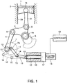
- a piston 1 of an internal combustion engine is accommodated in a cylinder 2a formed in a cylinder block 2 so as to be capable of performing a reciprocating motion therein.
- an upper link 3 is coupled to the piston 1 via a piston pin 1a. Another end of the upper link 3 is coupled to a lower link 4 via a pin 8.
- the lower link 4 is connected to a crankshaft 6 via a crank pin 6a. The reciprocating motion of the piston 1 within the cylinder 2a therefore causes the crankshaft 6 to rotate via the upper link 3 and the lower link 4.
- a compression ratio of the cylinder 2a generated by the reciprocating motion of the piston 1 varies according to an angle formed by the upper link 3 and the lower link 4.
- a variable compression ratio device varies the angle formed by the upper link 3 and lower link 4 by rotating the lower link 4 about the crank pin 6a.
- a control link 5 is coupled to the lower link 4 via a pin 9.
- the lower link 4 has a substantially triangular shape, the three vertices of which are connected to the upper link 3, the crankshaft 6, and the control link 5, respectively, via the pin 8, the crank pin 6a, and the pin 9.
- control link 5 Another end of the control link 5 is connected to a control shaft 7 that is parallel to the crankshaft 6 via an offset pin 10.
- a connection point at which the offset pin 10 connects the control link 5 to the control shaft 7 is provided in an offset position from the center of the control shaft 7. This setting is realized by fixing an eccentric cam to the control shaft and providing the eccentric cam with the connection point, for example.
- the compression ratio expresses the volume of a combustion chamber at bottom dead center of the piston 1 when the volume of the combustion chamber at top dead center of the piston 1 is assumed to be one.
- a maximum compression ratio is a compression ratio at which the combustion chamber volume at top dead center of the piston 1 reaches a minimum relative to the combustion chamber volume at bottom dead center of the piston 1.
- a minimum compression ratio is a compression ratio at which the combustion chamber volume at top dead center of the piston 1 reaches a maximum relative to the combustion chamber volume at bottom dead center of the piston 1.
- variable compression ratio device As a drive mechanism for rotationally displacing the control shaft 7, the variable compression ratio device comprises a fixing lever 11, a connecting link 12, an actuator rod 13, and an electric motor 18 that screw-feeds the actuator 13 via a ball screw reduction gear 17. An operation of the electric motor 18 is controlled by a programmable controller 19.
- One end of the fixing lever 11 is fixed to a rotation axis 7a of the control shaft 7. As a result, the control shaft 7 undergoes rotational displacement in accordance with the rotation of the fixing lever 11.
- Another end of the fixing lever 11 is connected to one end of the connecting link 12 via a connecting pin 14.
- Another end of the connecting link 12 is connected to a tip end of the actuator rod 13 via a connecting pin 15.
- Both ends of the connecting link 12 are forked, and the fixing lever 11 is connected to the connecting link 12 by the connecting pin 14, which penetrates the fork on one end of the connecting link 12 and one end portion of the fixing lever 11, the end portion of the fixing lever 11 being inserted into the fork.
- the actuator rod 13 is connected to the connecting link 12 by the connecting pin 15, which penetrates the fork on the other end of the connecting link 12 and an end portion of the actuator rod 13, the end portion of the actuator rod 13 being inserted into the fork.
- a male screw is formed on an outer periphery of the actuator rod 13.
- the ball screw reduction gear is constituted by a housing 16 and a reduction gear 17.
- a base end of the actuator rod 13 is accommodated in the housing 16.
- a screw feeding mechanism which is screwed to the male screw of the actuator rod 13 and converts a rotary motion into an axial motion is provided in the housing 16.
- the reduction gear 17 reduces the rotation of the electric motor 18 and transmits the reduced rotation to the screw feeding mechanism.
- the displacement direction and distance of the actuator rod 13 relative to the housing 16 are determined by operation control of the electric motor 18, which is performed by the controller 19.
- the controller 19 is constituted by a microcomputer comprising a central processing unit (CPU), read-only memory (ROM), random access memory (RAM), and an input/output interface (I/O interface).
- the controller may be constituted by a plurality of microcomputers.
- control shaft torque Tcs Combustion pressure in the cylinder 2a and an inertial force of the piston 1 are transmitted to the control shaft 7 via the upper link 3, lower link 4, and control link 5.
- the offset pin 10 is offset from the rotation axis 7a of the control shaft 7, and therefore the load thereof acts as a load that rotates the control shaft 7. In the following description, this load acting on the control shaft 7 will be referred to as control shaft torque Tcs.
- the variable compression ratio device comprises a holding mechanism for holding the control shaft 7 at a predetermined rotation angle against the control shaft torque Tcs.
- the holding mechanism may be constituted by a program set in the controller 19 to control the operation of the electric motor 18 such that torque in an opposite direction to the acting direction of the control shaft torque Tcs is applied to the control shaft 7, or by a mechanism that mechanically locks rotational displacement of the control shaft 7.
- the controller 19 varies the compression ratio of the internal combustion engine in accordance with operating conditions via the drive mechanism.
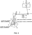
- FIG. 2 shows the arrangement of the control shaft 7, fixing lever 11, connecting link 12, and actuator rod 13 of the variable compression ratio device shown in FIG. 1 in a case where the internal combustion engine is set substantially at the minimum compression ratio.
- an angle formed by the connecting link 12 and the actuator rod 13 is set as ⁇ 1
- an angle formed by the fixing lever 11 and the connecting link 12 is set as ⁇ 2
- the rotation angle of the control shaft 7 is set as ⁇ cs .
- a horizontal direction is set as an X axis and a perpendicular direction thereto is set as a Y axis.
- the rotation angle ⁇ cs of the control shaft 7 is expressed by an angle formed by the X axis and the fixing lever 11.
- the counter-clockwise direction of the figure is set as a positive direction.
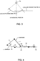
- FIG. 3 shows loci of the connecting pins 14 and 15 when the actuator rod 13 is caused to project from the housing 16 or caused to retreat into the housing 16.
- the locus of the connecting pin 14 forms an arc centering on the rotation axis 7a of the control shaft 7.
- the layout and dimensions of members including the drive mechanism are set such that the locus of the connecting pin 14 and an axis of the actuator rod 13 intersect at two compression ratios between the minimum compression ratio and the maximum compression ratio.
- FIG. 7A shows a condition in which the locus of the connecting pin 14 and the axis of the actuator rod 13 intersect at two compression ratios between the minimum compression ratio and the maximum compression ratio.
- FIG. 7B shows a case in which the locus of the connecting pin 14 and the axis of the actuator rod 13 do not intersect.
- a distance between the connecting pin 14 and the axis of the actuator rod 13 over the entire compression ratio region from the maximum compression ratio to the minimum compression ratio, or in other words D1 and D2 in the figure can be suppressed to be smaller than that of the case shown in FIG. 7B .
- a bending load applied to the actuator rod 13 by the housing 16 can be reduced in a contact portion between the actuator rod 13 and the housing 16.
- a movement region of the connecting pin 14 is set such that a region on the left side of a perpendicular extending from the rotation axis 7a of the control shaft 7 is larger than a region on the right side.
- D1 is set to be greater than D2 at all times.
- FIG. 8 shows a relationship between the rotation angle ⁇ cs of the control shaft 7 and a movement amount Vrod of the actuator rod 13 per unit rotation angle of the control shaft 7 corresponding to this setting.
- the movement amount Vrod of the actuator rod 13 may be replaced by a rotation speed of the electric motor 18.
- the abscissa in FIG. 8 shows the rotation angle ⁇ cs of the control shaft 7, and the ordinate shows the movement amount Vrod of the actuator rod 13.
- a solid line Vrod-r in the figure represents this embodiment.
- a dot-dash line Vrod-f in the figure represents the movement amount Vrod in the case of a forked connecting mechanism such as that of the prior art.
- the control shaft 7 rotates further in the counter-clockwise direction of the figure, leading to an increased compression ratio.
- the movement amount Vrod of the actuator rod 13 per rotation angle of the control shaft 7 is larger at a high compression ratio than a low compression ratio.
- variation in the rotation angle ⁇ cs of the control shaft 7 corresponding to the movement amount of the actuator rod 13 or the rotation speed of the electric motor 18 is smaller at a high compression ratio than a low compression ratio.
- the rotation angle ⁇ cs of the control shaft 7 can be controlled with a high degree of precision at a high compression ratio. Moreover, the effect of bending displacement of the actuator rod 13 on the rotation angle ⁇ cs of the control shaft 7 can be suppressed.
- the angle ⁇ 1 formed by the connecting link 12 and the actuator rod 13 at the maximum compression ratio is set to be closer to 180 degrees than ⁇ 1 at the minimum compression ratio.
- the connecting link 12 and actuator rod 13 are set to be closer to a straight line at the maximum compression ratio than at the minimum compression ratio.
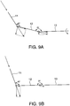
- FIG. 9A shows a case in which the angle ⁇ 1 formed by the connecting link 12 and actuator rod 13 is smaller than 180 degrees
- FIG. 9B shows a case in which the angle ⁇ 1 is equal to 180 degrees.
- the bending load acting on the actuator rod 13 increases as the connecting link 12 and the actuator rod 13 deflect and decreases as the connecting link 12 and the actuator rod 13 approach a straight line.
- the bending load acting on the actuator rod 13 increases as the compression ratio increases.
- variable compression ratio device is set such that the rotation angle ⁇ cs of the control shaft 7 is close to 90 degrees at the minimum compression ratio and close to 180 degrees at the maximum compression ratio.
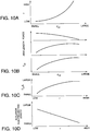
- the compression ratio increases as the rotation angle ⁇ cs of the control shaft 7 increases. Further, as shown in FIG. 10A , an increase rate of the compression ratio per unit rotation angle increases as the rotation angle ⁇ cs of the control shaft 7 increases.
- an axial direction load of the control link 5, which is transmitted via the offset pin 10, effects a rotary moment about the rotation axis 7a on the control shaft 7.
- An effective arm length of this moment increases as the compression ratio increases.
- the variable compression ratio device controls the rotation position of the control shaft 7 such that the compression ratio is low when an engine load is high and the compression ratio is high when the engine load is low. Accordingly, an axial direction force of the control link 5 decreases as the compression ratio increases.
- the control shaft torque Tcs is expressed by the product of the axial direction force of the control link 5 and the effective arm length. Considering the variation range of the two, variation in the effective arm length has a greater effect on the control shaft torque Tcs than variation in the axial direction force of the control link 5. As a result, the control shaft torque Tcs increases as the compression ratio increases, as shown in FIG. 10B . Further, a load Tcs / L obtained by dividing the control shaft torque Tcs by a length L of the fixing lever 11 also increases as the compression ratio increases.
- the bending load acting on the actuator rod 13 increases as the compression ratio increases.
- the projection amount of the actuator rod 13 from the housing 16 is small at a high compression ratio, and therefore the actuator rod 13 can achieve a high bearing capacity relative to the bending load.
- the projection amount of the actuator rod 13 from the housing 16 is large at a low compression ratio.
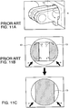
- FIG. 11A shows an actuator rod applied to the forked connection mechanism according to the prior art.
- FIG. 11B shows an outline of the cross-section of the actuator rod 13 in a region A surrounded by a broken line in FIG. 11A.
- FIG. 11C shows an outline of the cross-section of the actuator rod 13 to which the variable compression ratio device according to this embodiment is applied.
- FIG. 11A shows a state in which a fork is formed in the tip end of the actuator rod 13 employed in the variable compression ratio device according to the prior art.
- the actuator rod 13 When the actuator rod 13 is brought into contact with the housing 16 by a bending load indicated by an arrow in FIG. 11A , the actuator rod 13 receives a reactive force, indicated by an arrow P in FIG. 11B , from the housing 16, and as a result, a bending moment indicated by an arrow T in the figure acts on the forked part. As a result of this bending moment, bending deformation occurs in the actuator rod 13 such that great bending stress is generated in a root part of the forked portion. This bending stress increases as the depth of the fork increases.
- the tip end portion of the actuator rod 13 does not need to be forked.
- bending torque such as that shown by the arrow T in FIG. 11B does not act on the actuator rod 13. Accordingly, stress concentration on the tip end portion of the actuator rod 13 can be avoided.
- FIG. 12 and FIG. 13 correspond to FIG. 5 and FIG. 10A of the first embodiment, respectively.
- variable compression ratio device is constituted such that the movement amount of the actuator rod 13 per rotation angle of the control shaft 7 is larger at a high compression ratio than a low compression ratio.
- the rotation angle ⁇ cs of the control shaft 7 is set to be close to 180 degrees at the minimum compression ratio and to be close to 270 degrees at the maximum compression ratio.
- the compression ratio increases as the rotation angle ⁇ cs of the control shaft 7 increases.
- the increase rate of the compression ratio per unit rotation angle decreases as the rotation angle ⁇ cs of the control shaft 7 increases as shown in FIG. 13 .
- variation in the compression ratio relative to variation in the rotation angle ⁇ cs of the control shaft 7 decreases as the compression ratio approaches the maximum compression ratio, and therefore the precision of compression ratio control at a high compression ratio can be improved even further.
- FIGs. 14A and 14B Referring to FIGs. 14A and 14B , FIGs. 15-17 , FIGs. 22A and 22B , FIGs. 23A-23G , and FIGs. 24A-24G , a third embodiment of this invention will be described.
- FIG. 14A shows the state of the variable compression ratio device in the vicinity of the minimum compression ratio.
- FIG. 14B shows the state of the variable compression ratio device in the vicinity of the maximum compression ratio.
- the rotation angle ⁇ cs of the control shaft 7 at the minimum compression ratio is close to 90 degrees
- the rotation angle ⁇ cs of the control shaft 7 at the maximum compression ratio is close to 180 degrees. Accordingly, the effective arm length by which a load F3 acting on the control shaft 7 is converted into the control shaft torque Tcs reaches a maximum at the maximum compression ratio.
- the fixing lever 11, connecting link 12, and actuator rod 13 are disposed such that the angle ⁇ 2 formed by the connecting link 12 and the actuator rod 13 reaches a maximum at the maximum compression ratio.
- a component that acts in a transverse direction of the actuator rod 13 is set as F1
- a component that acts in the axial direction is set as F2.
- the control shaft torque Tcs which is expressed by the product of the load F3 acting on the control shaft 7 and the effective arm length, is affected more greatly by the effective arm length. Therefore, the control shaft torque Tcs reaches a maximum at the maximum compression ratio. At the compression ratio at which the effective arm length reaches a maximum, or in other words the compression ratio at which the control shaft torque Tcs reaches a maximum, the ratio between F1 and F2 reaches a minimum.
- the component F1 in the transverse direction of the actuator rod 13 acts on the actuator rod 13 as a bending load. Therefore, as F1 / F2 decreases, the bending load acting on the actuator rod 13 decreases relatively.
- an amount of displacement in the piston top dead center position per unit rotation angle of the control shaft 7 is larger at a high compression ratio than a low compression ratio.
- the control shaft torque Tcs is greater at a high compression ratio than a low compression ratio.
- a load generated by combustion acts to rotate the control shaft 7 in the clockwise direction of the figure, or in other words a low compression ratio direction.
- the compression ratio can be varied quickly from a high compression ratio region, in which knocking is likely to occur, to a low compression ratio.
- an acceleration performance of the internal combustion engine can be improved while avoiding knocking.
- variable compression ratio device there is no need or almost no need to apply the torque of the electric motor 18 when varying the compression ratio from a high compression ratio to a low compression ratio to ensure that the compression ratio variation speed does not become excessive as the compression ratio decreases. Accordingly, the amount of energy consumed to drive the electric motor 18 can be reduced.
- a constitution in which the effective arm length reaches a maximum at the maximum compression ratio and reaches a minimum at the minimum compression ratio, and in which F1 / F2 reaches a minimum at the maximum compression ratio, is not limited to the constitution shown in FIG. 14 .
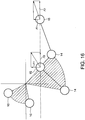
- FIGs. 15-17 show a variation of this embodiment relating to the positions of the offset pin 10 and the connecting pin 14 at the maximum compression ratio and the minimum compression ratio.
- the displacement range of the offset pin 10, the connecting pin 14, and the connecting pin 15 is indicated here by referring to zero degrees ⁇ ⁇ cs ⁇ 90 degrees as a first quadrant, 90 degrees ⁇ ⁇ cs ⁇ 180 degrees as a second quadrant, 180 degrees ⁇ ⁇ cs ⁇ 270 degrees as a third quadrant, and 270 degrees ⁇ ⁇ cs ⁇ 360 degrees as a fourth quadrant.
- substantially the entire region of displacement of the offset pin 10 is positioned in the first quadrant, and substantially the entire region of displacement of the connecting pin 14 is positioned in the fourth quadrant.
- the locus of the connecting pin 14 is positioned above the axis of the actuator rod 13 over substantially the entire region from the maximum compression ratio to the minimum compression ratio, but contacts or intersects the axis of the actuator rod 13 in the vicinity of the maximum compression ratio.
- substantially the entire region of displacement of the offset pin 10 is positioned in the second quadrant, and substantially the entire region of displacement of the connecting pin 14 is positioned in the fourth quadrant.
- the locus of the connecting pin 14 is positioned below the axis of the actuator rod 13 over the entire region from the maximum compression ratio to the minimum compression ratio.
- substantially the entire region of displacement of the offset pin 10 is positioned in the first quadrant, and substantially the entire region of displacement of the connecting pin 14 is positioned in the third quadrant.
- the locus of the connecting pin 14 is positioned below the axis of the actuator rod 13 over substantially the entire region from the maximum compression ratio to the minimum compression ratio.
- FIGs. 22A and 23A With the constitution of the variable compression ratio device shown in FIGs. 14A, 14B and 15 , a distance y2 between the axis of the actuator rod 13 and the center of the control shaft 7 is larger than a distance y1 between the connecting pin 14 and the center of the control shaft 7 in relation to the transverse direction of the actuator rod 13 over substantially the entire compression ratio region.
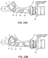
- FIG. 22A shows the state of the fixing lever 11, connecting link 12, and actuator rod 13 at the maximum compression ratio.
- FIG. 22B shows the state of the fixing lever 11, connecting link 12, and actuator rod 13 at the minimum compression ratio. Solid line above the actuator rod 13 in the figures represents the locus of a lower end of the lower link 4 during an operation.
- the magnitude of the transverse direction load F1 applied to the actuator rod 13 in the variable compression ratio device shown in FIGs. 14A, 14B and 15 is substantially constant over the entire compression ratio region.
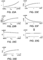
- FIGs. 23A-23G show characteristics of the variable compression ratio devices shown in FIGs. 14A, 14B and 15 .
- FIG. 23A shows a characteristic of compression ratio variation relative to the rotation angle ⁇ cs of the control shaft 7.
- the compression ratio increases in the form of a quadratic curve as the rotation angle ⁇ cs of the control shaft 7 increases.
- FIG. 23B shows a characteristic of effective arm length variation relative to the rotation angle ⁇ cs of the control shaft 7.
- the effective arm length increases as the rotation angle ⁇ cs of the control shaft 7 increases, but the increase rate of the effective arm length decreases as the rotation angle ⁇ cs of the control shaft 7 increases.
- FIG. 23C shows a characteristic of variation in the load F3 on the control shaft 7 relative to the rotation angle ⁇ cs of the control shaft 7.
- the load F3 decreases as the rotation angle ⁇ cs of the control shaft 7 increases.
- FIG. 23D shows a relationship between the rotation angle ⁇ cs of the control shaft 7 and the control shaft torque Tcs.
- the control shaft torque Tcs is the product of the load F3 on the control shaft 7 and the effective arm length.
- the effective arm length affects the control shaft torque Tcs greatly, and therefore the control shaft torque Tcs exhibits a similar characteristic to the effective arm length.
- FIG. 23E shows a relationship between the compression ratio and a value obtained by dividing the control shaft torque Tcs by the length L of the fixing lever 11, or in other words the magnitude of the load acting on the connecting pin 15.
- the load acting on the connecting pin 15 also exhibits a similar characteristic to the effective arm length.
- FIG. 23F shows variation in F1 / F2 relative to the compression ratio. As the compression ratio increases, F1 / F2 decreases. The variation rate thereof decreases as the compression ratio increases.
- the connecting pin 14 is in the third quadrant in the vicinity of the maximum compression ratio, and therefore, strictly speaking, the characteristic in the vicinity of the maximum compression ratio in FIGs. 23E and 23F differs from that of the constitution shown in FIG. 14 . However, when compared over the entire compression ratio region, these characteristics may be considered more or less identical.
- FIG. 23G shows variation in the transverse direction load F1 applied to the actuator rod 13 relative to the compression ratio.
- the load F1 is expressed by the product of Tcs / L shown in FIG. 23E and F1 / F2 shown in FIG. 23F .
- Tcs / L increases and the variation rate thereof decreases.
- F1 / F2 decreases and the variation rate thereof also decreases. Since Tcs / L and F1 / F2 cancel each other out, the load F1 remains substantially constant, regardless of the compression ratio.
- FIGs. 24A-24G show characteristics of the variable compression ratio devices shown in FIGs. 16 and 17 .
- FIGs. 24A-24E are similar to those shown in FIGs. 23A-23E .
- the characteristic shown in FIG. 24F while the value of F1 / F2 decreases as the compression ratio increases as in the case of FIG. 23F , the variation rate thereof increases, in contrast to the characteristic shown in FIG. 23F . Therefore, in the variable compression ratio device constituted as shown in FIGs. 16 and 17 , Tcs / L and F1 / F2 do not cancel each other out, and the magnitude of F1 reaches a maximum at an intermediate compression ratio, as shown in FIG. 24G .
- variable compression ratio device constituted as shown in FIGs. 14A, 14B and 15 In comparison with the variable compression ratio devices constituted as shown in FIG. 16 and FIG. 17 , in the variable compression ratio device constituted as shown in FIGs. 14A, 14B and 15 , F1 increases in the vicinity of the minimum compression ratio and the maximum compression ratio, but decreases in other regions and has a smaller maximum value. When considering the entire compression ratio region, the variable compression ratio device constituted as shown in FIGs. 14A, 14B and 15 exhibits a greater F1 reduction effect than the variable compression ratio device constituted as shown in FIG. 16 or FIG. 17 .
- a variable compression ratio device differs from the first embodiment in the displacement region of the offset pin 10, the connecting pin 14, and the connecting pin 15.
- the offset pin 10 displaces over the second quadrant and third quadrant so as to be positioned in the second quadrant at the minimum compression ratio and in the third quadrant at the maximum compression ratio.
- the connecting pin 14 displaces over the third quadrant and fourth quadrant so as to be positioned in the third quadrant at the minimum compression ratio and in the fourth quadrant at the maximum compression ratio. Furthermore, the connecting pin 14 is positioned above the axis of the actuator rod 13 throughout the entire displacement region, and comes closest to the axis of the actuator rod 13 at the intermediate compression ratio.
- the effective arm length for converting an axial direction load of the control link 5 into a rotational torque of the rotation axis 7a reaches a maximum when the rotation angle ⁇ cs of the control shaft 7 reaches 270 degrees at the intermediate compression ratio.
- the distance between the connecting pin 14 and the axis of the actuator rod 13 is at a minimum, and therefore F1 / F2 is also at a minimum.
- the displacement amount of the piston top dead center position per unit rotation angle of the control shaft 7 has an equal maximum value to a case in which the variation range of the offset pin 10 is limited to the first quadrant or the second quadrant alone, but a larger minimum value.
- the displacement amount of the piston top dead center position per unit rotation angle of the control shaft 7 is larger in terms of the entire compression ratio region.
- variable compression ratio device as shown in FIGs. 19-21 .
- FIGs. 19-21 show a variation of this embodiment relating to the positions of the offset pin 10 and the connecting pin 14 at the maximum compression ratio, the intermediate compression ratio, and the minimum compression ratio.
- the offset pin 10 displaces over the fourth quadrant and the first quadrant so as to be positioned in the fourth quadrant at the maximum compression ratio and in the first quadrant at the minimum compression ratio.
- the rotation angle ⁇ cs of the control shaft 7 is substantially zero degrees.
- the connecting pin 14 displaces over the third quadrant and the fourth quadrant so as to be positioned in the third quadrant at the maximum compression ratio and in the fourth quadrant at the minimum compression ratio.
- the rotation angle ⁇ cs of the control shaft 7 is substantially 270 degrees.
- the locus of the connecting pin 14 is positioned above the axis of the actuator rod 13 over the entire compression ratio region.
- the offset pin 10 displaces over the second quadrant and the third quadrant so as to be positioned in the third quadrant at the maximum compression ratio and in the second quadrant at the minimum compression ratio.
- the rotation angle ⁇ cs of the control shaft 7 is substantially 180 degrees.
- the connecting pin 14 displaces over the third quadrant and the fourth quadrant so as to be positioned in the third quadrant at the minimum compression ratio and in the fourth quadrant at the maximum compression ratio.
- the rotation angle ⁇ cs of the control shaft 7 is substantially 270 degrees.
- the locus of the connecting pin 14 is positioned above the axis of the actuator rod 13 at the maximum compression ratio and the minimum compression ratio, and either contacts or is positioned below the axis of the actuator rod 13 at the intermediate compression ratio.
- the offset pin 10 displaces over the fourth quadrant and the first quadrant so as to be positioned in the fourth quadrant at the maximum compression ratio and in the first quadrant at the minimum compression ratio.
- the rotation angle ⁇ cs of the control shaft 7 is close to zero degrees.
- the connecting pin 14 displaces over the third quadrant and the fourth quadrant so as to be positioned in the third quadrant at the maximum compression ratio and in the fourth quadrant at the minimum compression ratio.
- the rotation angle ⁇ cs of the control shaft 7 is substantially 270 degrees.
- the locus of the connecting pin 14 is positioned above the axis of the actuator rod 13 at the maximum compression ratio and the minimum compression ratio, and either contacts or is positioned below the axis of the actuator rod 13 at the intermediate compression ratio.
- the displacement amount of the top dead center position of the piston 1 per unit rotation angle of the control shaft 7 reaches a maximum at the intermediate compression ratio and reaches a minimum at the maximum compression ratio and the minimum compression ratio.
- the minimum value thereof is larger than the minimum value of the variable compression ratio device according to the third embodiment, shown in FIGs. 14A, 14B and 15 .
- the displacement amount of the top dead center position of the piston 1 per unit rotation angle of the control shaft 7 is larger over the entire compression ratio region.
- the combustion load applies a greater torque on the control shaft 7 to rotate it in a direction toward the low compression ratio side. Hence, the responsiveness of an operation to modify the compression ratio in a low compression ratio direction can be improved.
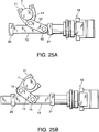
- FIGs. 25A and 25B A fifth embodiment of this invention will now be described with reference to FIGs. 25A and 25B .
- This embodiment is similar to the first embodiment, but differs therefrom in the constitution of the actuator rod 13.
- This embodiment comprises a support member 20 and a support member 21 which latch the second connecting pin 15 to an intermediate portion of the actuator rod 13 and support the actuator rod 13.
- the support member 20 and the support member 21 are disposed on either side of the connecting pin 15 relative to the axial direction of the actuator rod 13.
- the actuator rod 13 penetrates the support member 20 and the support member 21 so as to be free to slide.
- the support members 20 and 21 are fixed to the cylinder block of the internal combustion engine, for example.
- the housing 16 does not have to be increased in size to secure rigidity.
- the distance y1 between the connecting pin 14 and the center of the control shaft 7 and a ratio y2 / y1 of the distance y2 between the axis of the actuator rod 13 and the center of the control shaft 7 and the distance y1 between the connecting pin 14 and the center of the control shaft 7, in relation to the transverse direction of the actuator rod 13, may be set larger than the variable compression ratio device according to the third embodiment, shown in FIGs. 22A and 22B .
- the actuator rod 13 and the control shaft 7 can be disposed in removed positions. Disposing the actuator rod 13 and the control shaft 7 in this manner is preferable to avoid interference between peripheral components of the actuator rod 13 and support members of the control shaft 7, members such as the control link 5 and the lower link 4, and so on.
Landscapes
- Engineering & Computer Science (AREA)
- Chemical & Material Sciences (AREA)
- Combustion & Propulsion (AREA)
- Mechanical Engineering (AREA)
- General Engineering & Computer Science (AREA)
- Output Control And Ontrol Of Special Type Engine (AREA)
Claims (18)
- Eine Variabel-Kompressions-Verhältnis-Vorrichtung für eine Brenn-Kraft-Maschine mit innerer Verbrennung, die umfasst:eine Steuer-Welle (7), die ein Kompressions-Verhältnis der Brenn-Kraft-Maschine mit innerer Verbrennung in Übereinstimmung mit einer Dreh-Verlagerung variiert;einen Linear-Aktuator (13, 16-18);einen Hebel (11), der integral mit der Steuer-Welle (7) dreht;einen Verbindungs-Lenker (12), der mit dem Linear-Aktuator (13, 16-18) verbunden ist; undeinen ersten Verbindungs-Stift (14), der den Hebel (11) mit dem Verbindungs-Lenker (12) an einem ersten Punkt, der von einer Dreh-Achse (7a) der Steuer-Welle (7) versetzt ist, verbindet, wobei die Vorrichtung weiter umfasst:eine Mehrzahl von Lenkern (3, 4), die einen Kolben (1) der Brenn-Kraft-Maschine mit innerer Verbrennung mit einer Kurbel-Welle (6) verbinden; undeinen Steuer-Lenker (5), der einen der Mehrzahl von Lenkern (3, 4) mit einem zweiten Punkt, der von der Dreh-Achse (7a) der Steuer-Welle (7) versetzt ist und integral mit der Steuer-Welle (7) dreht, verbindet.
- Eine Variabel-Kompressions-Verhältnis-Vorrichtung gemäß Anspruch 1, wobei der zweite Punkt durch einen zweiten Verbindungs-Stift (15), der den Verbindungs-Lenker (12) mit dem Linear-Aktuator (13, 16-18) verbindet, bestimmt ist.
- Eine Variabel-Kompressions-Verhältnis-Vorrichtung gemäß Anspruch 2, wobei der Linear-Aktuator (13, 16-18) umfasst:ein Gehäuse (16); undeinen Aktuator-Stab (13), der relativ zu dem Gehäuse (16) vorgeht und zurückzieht, und mit dem Verbindungs-Lenker (12) durch den zweiten Verbindungs-Stift (15) verbunden ist, unddie Variabel-Kompressions-Verhältnis-Vorrichtung ist bestimmt, um das Kompressions-Verhältnis der Brenn-Kraft-Maschine mit innerer Verbrennung zu erhöhen, indem der Aktuator-Stab (13) sich zurückzieht.
- Eine Variabel-Kompressions-Verhältnis-Vorrichtung gemäß Anspruch 3, wobei die Dreh-Verlagerung der Steuer-Welle (7), die einer Verlagerung des Aktuator-Stabs (13) entspricht, bei einem Hoch-Kompressions-Verhältnis kleiner als bei einem Niedrig-Kompressions-Verhältnis ist, und ein Niedrig-Kompressions-Verhältnis-Seiten-Betriebs-Bereich des Aktuator-Stabs (13) ist gesetzt um größer zu sein als ein Hoch-Kompressions-Verhältnis-Seiten-Betriebs-Bereich, in Relation zu einer senkrechten Erstreckung von der Dreh-Achse (7a) von der Steuer-Welle (7) zu einer Achse des Aktuator-Stabs (13).
- Eine Variabel-Kompressions-Verhältnis-Vorrichtung gemäß Anspruch 3 oder 4, wobei der Verbindungs-Lenker (12) und der Aktuator-Stab (13) bei einem Maximal-Kompressions-Verhältnis eine im Wesentlichen gerade Linie bilden.
- Eine Variabel-Kompressions-Verhältnis-Vorrichtung gemäß zu irgendeinem der Ansprüche 3 bis 5, wobei ein Ort des ersten Verbindungs-Stifts (14) die Achse des Aktuator-Stabs (13) schneidet.
- Eine Variabel-Kompressions-Verhältnis-Vorrichtung gemäß zu irgendeinem der Ansprüche 3 bis 6, wobei der zweite Punkt an eine Position gesetzt ist, an der eine Arm-Länge von einem Moment, aufgebracht auf die Steuer-Welle (7) durch den Steuer-Lenker (5), sich erhöht, wenn das Kompressions-Verhältnis sich erhöht.
- Eine Variabel-Kompressions-Verhältnis-Vorrichtung gemäß zu irgendeinem der Ansprüche 3 bis 7, wobei der zweite Punkt an eine Position gesetzt ist, an der eine Arm-Länge von dem Moment, aufgebracht auf die Steuer-Welle (7) durch den Steuer-Lenker (5), abnimmt, wenn das Kompressions-Verhältnis abnimmt.
- Eine Variabel-Kompressions-Verhältnis-Vorrichtung gemäß zu irgendeinem der Ansprüche 3 bis 8, wobei der Verbindungs-Lenker (12) gabelförmig ist, und ein Ende von dem Aktuator-Stab (13) über den zweiten Verbindungs-Stift (15) mit der Gabel verbunden ist.
- Eine Variabel-Kompressions-Verhältnis-Vorrichtung gemäß zu irgendeinem der Ansprüche 3 bis 9, wobei der Linear-Aktuator (13, 16-18) umfasst:einen Elektro-Motor (18); undein Kugel-Umlauf-Reduktions-Getriebe (17), das eine Drehung von dem Elektro-Motor (18) in eine Linear-Bewegung unter Verwendung eines Schrauben-Mechanismus umwandelt.
- Eine Variabel-Kompressions-Verhältnis-Vorrichtung gemäß zu irgendeinem der Ansprüche 3 bis 10, wobei, wenn eine Komponente einer Last, aufgebracht auf den Aktuator-Stab (13) durch den Verbindungs-Lenker (12), die in einer Quer-Richtung von dem den Aktuator-Stab (13) wirkt, als F1 definiert ist, eine Komponente der Last, aufgebracht auf den Aktuator-Stab (13) durch den Verbindungs-Lenker (12), die in eine Axial-Richtung von dem Aktuator-Stab (13) wirkt, als F2 definiert ist, und ein Moment, aufgebracht auf die Steuer-Welle (7) durch den Steuer-Lenker (5), als ein Steuer-Wellen-Moment definiert ist, ist die Variabel-Kompressions-Verhältnis-Vorrichtung gebildet, so dass ein Kompressions-Verhältnis an dem das Steuer-Wellen-Moment ein Maximum erreicht, ein Verhältnis F1/F2 zwischen der Last F1 und der Last F2 ein Minimum erreicht.
- Eine Variabel-Kompressions-Verhältnis-Vorrichtung gemäß Anspruch 11, wobei das Kompressions-Verhältnis, an dem das Steuer-Wellen-Moment ein Maximum erreicht, gleich einem Kompressions-Verhältnis ist, an dem die Armlänge von dem Moment, aufgebracht auf die Steuer-Welle (7) durch den Steuer-Lenker (5), ein Maximum erreicht.
- Eine Variabel-Kompressions-Verhältnis-Vorrichtung gemäß Anspruch 11 oder 12, wobei die Variabel-Kompressions-Verhältnis-Vorrichtung weiter ausgebildet ist, so dass das Steuer-Wellen-Moment an einer Hoch-Kompressions-Verhältnis-Seite von einem Zwischen-Kompressions-Verhältnis, angeordnet zwischen dem Maximal-Kompressions-Verhältnis und einem Minimal-Kompressions-Verhältnis, größer ist als zu einer Niedrig-Kompressions-Verhältnis-Seite von dem Zwischen-Kompressions-Verhältnis, und das Verhältnis F1/F2 zwischen der Last F1 und der Last F2 ist an der Hoch-Kompressions-Verhältnis-Seite kleiner als an der Niedrig-Kompressions-Verhältnis-Seite.
- Eine Variabel-Kompressions-Verhältnis-Vorrichtung gemäß zu irgendeinem der Ansprüche 11 bis 13, wobei die Variabel-Kompressions-Verhältnis-Vorrichtung weiter ausgebildet ist, so dass das Steuer-Wellen-Moment an der Hoch-Kompressions-Verhältnis-Seite von dem Zwischen-Kompressions-Verhältnis, angeordnet zwischen einem Maximum-Kompressions-Verhältnis und einem Minimum-Kompressions-Verhältnis, größer ist als zu der Niedrig-Kompressions-Verhältnis-Seite von dem Zwischen-Kompressions-Verhältnis, und ein mittlerer Abstand zwischen dem zweiten Verbindungs-Stift und der Achse von dem Aktuator-Stab (13) ist an der Hoch-Kompressions-Verhältnis-Seite kürzer als an der Niedrig-Kompressions-Verhältnis-Seite.
- Eine Variabel-Kompressions-Verhältnis-Vorrichtung gemäß Anspruch 11 oder 12, wobei die Variabel-Kompressions-Verhältnis-Vorrichtung weiter ausgebildet ist, so dass das Steuer-Wellen-Moment ein Maximum erreicht und das Verhältnis F1/F2 zwischen der Last L1 und der Last F2 ein Minimum erreicht, an einem Zwischen-Kompressions-Verhältnis, angeordnet zwischen einem Minimum-Kompressions-Verhältnis und einem Maximum-Kompressions-Verhältnis.
- Eine Variabel-Kompressions-Verhältnis-Vorrichtung gemäß zu irgendeinem der Ansprüche 11, 12 und 15, wobei die Variabel-Kompressions-Verhältnis-Vorrichtung weiter ausgebildet ist, so dass das Steuer-Wellen-Moment ein Maximum erreicht und ein Abstand zwischen dem ersten Verbindungs-Stift und der Achse des Aktuator-Stabs (13) ein Minimum erreicht, an dem Zwischen-Kompressions-Verhältnis, angeordnet zwischen einem Maximum-Kompressions-Verhältnis und einem Minimum-Kompressions-Verhältnis.
- Eine Variabel-Kompressions-Verhältnis-Vorrichtung gemäß zu Anspruch 13 oder 15, wobei in Relation zu der Quer-Richtung von dem Aktuator-Stab (13), ein Abstand zwischen dem ersten Verbindungs-Stift und der Dreh-Achse (7a) der Steuer-Welle (7) größer als ein Abstand zwischen der Achse des Aktuator-Stabs (13) und der Dreh-Achse (7a) von der Steuer-Welle (7) über einen gesamten Kompressions-Verhältnisbereich ist.
- Eine Variabel-Kompressions-Verhältnis-Vorrichtung gemäß zu irgendeinem der Ansprüche 11 bis 17, die weiter umfasst eine Gruppe von Lager-Elementen (20, 21), die den Verbindungs-Lenker (12) mit einer Zwischen-Position von dem Aktuator-Stab (13) über den zweiten Verbindungs-Stift (15) verbinden und den Aktuator-Stab (13) lagert, um an einer Seite des zweiten Verbindungs-Stifts (15), in Relation zu einer Axial-Richtung von dem Aktuator-Stab (13), frei zu gleiten.
Applications Claiming Priority (1)
| Application Number | Priority Date | Filing Date | Title |
|---|---|---|---|
| JP2007209516A JP4882912B2 (ja) | 2007-08-10 | 2007-08-10 | 可変圧縮比内燃機関 |
Publications (4)
| Publication Number | Publication Date |
|---|---|
| EP2022959A2 EP2022959A2 (de) | 2009-02-11 |
| EP2022959A3 EP2022959A3 (de) | 2014-06-18 |
| EP2022959B1 true EP2022959B1 (de) | 2019-09-18 |
| EP2022959B8 EP2022959B8 (de) | 2019-10-23 |
Family
ID=39926559
Family Applications (1)
| Application Number | Title | Priority Date | Filing Date |
|---|---|---|---|
| EP08013187.3A Ceased EP2022959B8 (de) | 2007-08-10 | 2008-07-22 | Variable druckverhältnisvorrichtung für einen verbrennungsmotor |
Country Status (3)
| Country | Link |
|---|---|
| US (1) | US8397683B2 (de) |
| EP (1) | EP2022959B8 (de) |
| JP (1) | JP4882912B2 (de) |
Families Citing this family (50)
| Publication number | Priority date | Publication date | Assignee | Title |
|---|---|---|---|---|
| JP5029290B2 (ja) * | 2007-10-29 | 2012-09-19 | 日産自動車株式会社 | 可変圧縮比エンジン |
| JP5182167B2 (ja) * | 2009-03-13 | 2013-04-10 | 日産自動車株式会社 | 可変圧縮比機構 |
| US20110155106A1 (en) * | 2009-12-29 | 2011-06-30 | Von Mayenburg Michael | Internal combustion engine with variable compression ratio |
| JP5471560B2 (ja) * | 2010-02-16 | 2014-04-16 | 日産自動車株式会社 | 内燃機関の可変圧縮比装置 |
| KR101210021B1 (ko) | 2011-08-18 | 2012-12-07 | 현대자동차주식회사 | 듀얼 편심 링크가 구비된 가변 압축비 장치 |
| DE102011116952B4 (de) | 2011-10-26 | 2015-09-03 | Audi Ag | Mehrgelenkskurbeltrieb einer Brennkraftmaschine sowie Verfahren zum Betreiben eines Mehrgelenkskurbeltriebs |
| US8851030B2 (en) | 2012-03-23 | 2014-10-07 | Michael von Mayenburg | Combustion engine with stepwise variable compression ratio (SVCR) |
| JP5888108B2 (ja) * | 2012-05-18 | 2016-03-16 | 日産自動車株式会社 | 可変圧縮比内燃機関 |
| JP2014034927A (ja) * | 2012-08-09 | 2014-02-24 | Honda Motor Co Ltd | 復リンク式の内燃機関 |
| EP2947295B1 (de) * | 2013-01-17 | 2017-02-08 | Nissan Motor Co., Ltd. | Verbrennungsmotor mit variabler verdichtung |
| CN103233824B (zh) * | 2013-04-28 | 2015-08-26 | 李宜平 | 一种发动机控容恒压系统 |
| DE202014004439U1 (de) | 2014-02-04 | 2015-05-05 | Ovalo Gmbh | Anordnung zum Antreiben einer Verstellwelle zum Verstellen des Expansionshubes und/oder des Verdichtungsverhältnisses eines Verbrennungsmotors |
| DE102014201981B4 (de) | 2014-02-04 | 2021-11-04 | Ovalo Gmbh | Anordnung zum Antreiben einer Verstellwelle zum Verstellen des Expansionshubes und/oder des Verdichtungsverhältnisses eines Verbrennungsmotors |
| DE102014201983A1 (de) | 2014-02-04 | 2015-08-06 | Ovalo Gmbh | Anordnung zum Antreiben einer Verstellwelle eines Kraftfahrzeuges |
| DE102014201979B4 (de) | 2014-02-04 | 2022-10-06 | Ovalo Gmbh | Anordnung zum Antreiben einer Verstellwelle zum Verstellen des Expansionshubes und/oder des Verdichtungsverhältnisses eines Verbrennungsmotors |
| DE102014201985A1 (de) | 2014-02-04 | 2015-08-06 | Ovalo Gmbh | Anordnung zum Antreiben einer Verstellwelle eines Kraftfahrzeugs |
| DE102014201984A1 (de) | 2014-02-04 | 2015-08-06 | Ovalo Gmbh | Anordnung zum Antreiben einer Verstellwelle eines Kraftfahrzeugs |
| DE102014201978B4 (de) | 2014-02-04 | 2021-10-28 | Ovalo Gmbh | Anordnung zum Antreiben einer Verstellwelle zum Verstellen des Expansionshubes und/oder des Verdichtungsverhältnisses eines Verbrennungsmotors |
| DE102014201982A1 (de) | 2014-02-04 | 2015-08-06 | Ovalo Gmbh | Verbrennungsmotor mit einem Aktuator zum Antreiben einer Verstellwelle zum Verstellen des Expansionshubes und/oder des Verdichtungsverhältnisses des Verbrennungsmotors |
| DE102014201986A1 (de) | 2014-02-04 | 2015-08-06 | Ovalo Gmbh | Kraftfahrzeugbaugruppe mit einem Aktuator zum Antreiben einer Verstellwelle |
| DE102014112689B4 (de) | 2014-02-04 | 2024-08-08 | Ovalo Gmbh | Koaxialgetriebe und Anordnung zum Antreiben einer Verstellwelle zum Verstellen des Expansionshubes und/oder des Verdichtungsverhältnisses eines Verbrennungsmotors |
| DE102014014706B3 (de) * | 2014-10-02 | 2016-04-07 | Audi Ag | Mehrgelenkskurbeltrieb für eine Brennkraftmaschine mit axial beweglicher Steuerwelle und kulissengeführten drehbaren Exzentern auf der Steuerwelle |
| DE102014018525B4 (de) | 2014-12-12 | 2018-05-30 | Audi Ag | Mehrgelenkskurbeltrieb für eine Brennkraftmaschine mit Fail-Safe-Exzenterwellen-Feststellvorrichtung |
| DE102015111441B4 (de) * | 2015-07-15 | 2021-03-04 | Iav Gmbh Ingenieurgesellschaft Auto Und Verkehr | Verstelleinrichtung für eine Brennkraftmaschine mit variablem Verdichtungsverhältnis |
| DE102015017286B3 (de) | 2015-08-03 | 2023-05-04 | Ovalo Gmbh | Aktuator, insbesondere zum Ankoppeln an die Verstellwelle eines Verbrennungsmotors zum Einstellen des Expansionshubes und/oder des Verdichtungsverhältnisses |
| DE102015112690B4 (de) | 2015-08-03 | 2023-04-20 | Ovalo Gmbh | Aktuatorsystem, insbesondere zum Ankoppeln an die Verstellwelle eines Verbrennungsmotors zum Einstellen des Expansionshubes und/oder des Verdichtungsverhältnisses |
| DE102015112693A1 (de) | 2015-08-03 | 2017-02-09 | Ovalo Gmbh | Aktuator, insbesondere zum Ankoppeln an die Verstellwelle eines Verbrennungsmotors zum Einstellen des Expansionshubes und/oder des Verdichtungsverhältnisses |
| JP6934858B2 (ja) | 2015-08-03 | 2021-09-15 | オバロ ゲーエムベーハー | 特に膨張ストローク及び/又は圧縮比を調節する内燃機関の調節軸へ連結するためのアクチュエータ |
| DE102015112689B3 (de) * | 2015-08-03 | 2016-10-06 | Ovalo Gmbh | Aktuator, insbesondere zum Ankoppeln an die Verstellwelle eines Verbrennungsmotors zum Einstellen des Expansionshubes und/oder des Verdichtungsverhältnisses |
| DE102015112695B3 (de) * | 2015-08-03 | 2016-10-06 | Ovalo Gmbh | Aktuator, insbesondere zum Ankoppeln an die Verstellwelle eines Verbrennungsmotors zum Einstellen des Expansionshubes und/oder des Verdichtungsverhältnisses |
| DE102015112688B4 (de) | 2015-08-03 | 2018-11-08 | Ovalo Gmbh | Aktuator, insbesondere zum Ankoppeln an die Verstellwelle eines Verbrennungsmotors zum Einstellen des Expansionshubes und/oder des Verdichtungsverhältnisses |
| DE102015112692B3 (de) * | 2015-08-03 | 2016-10-13 | Ovalo Gmbh | Aktuator, insbesondere zum Ankoppeln an die Verstellwelle eines Verbrennungsmotors zum Einstellen des Expansionshubes und/oder des Verdichtungsverhältnisses |
| DE102015112684A1 (de) | 2015-08-03 | 2017-02-09 | Ovalo Gmbh | Aktuator, insbesondere zum Ankoppeln an die Verstellwelle eines Verbrennungsmotors zum Einstellen des Expansionshubes und/oder des Verdichtungsverhältnisses |
| LU92788B1 (de) * | 2015-08-03 | 2017-02-14 | Ovalo Gmbh | Aktuator, insbesondere zum Ankoppeln an die Verstellwelle eines Verbrennuzngsmotors zum Einstellen des Expansionshubes und/oder des Verdichtungsverhältnisses |
| DE102015112691A1 (de) | 2015-08-03 | 2017-02-09 | Ovalo Gmbh | Aktuator, insbesondere zum Ankoppeln an die Verstellwelle eines Verbrennungsmotors zum Einstellen des Expansionshubes und/oder des Verdichtungsverhältnisses |
| DE102015114823B4 (de) | 2015-09-04 | 2019-05-09 | Ovalo Gmbh | Aktuator, der zum Verändern des Expansionshubes und/oder des Verdichtungsverhältnisses eines Verbrennungsmotors ausgebildet ist; System beinhaltend einen Aktuator und einen Verbrennungsmotor |
| DE102015015616A1 (de) | 2015-12-03 | 2017-06-08 | Audi Ag | Mehrgelenkskurbeltrieb für eine Brennkraftmaschine, Brennkraftmaschine mit einem Mehrgelenkskurbeltrieb sowie Verfahren zum Betreiben eines Mehrgelenkskurbeltriebs |
| DE102016201035A1 (de) * | 2016-01-26 | 2017-07-27 | Schaeffler Technologies AG & Co. KG | Hubkolbenbrennkraftmaschine mit veränderlichem Verdichtungsverhältnis |
| US10125679B2 (en) * | 2016-03-29 | 2018-11-13 | GM Global Technology Operations LLC | Independent compression and expansion ratio engine with variable compression ratio |
| US10428863B2 (en) | 2017-06-21 | 2019-10-01 | GM Global Technology Operations LLC | Variable compression ratio engine |
| KR102406127B1 (ko) * | 2017-10-16 | 2022-06-07 | 현대자동차 주식회사 | 가변 압축비 엔진 |
| CN110671198B (zh) * | 2018-12-29 | 2021-07-20 | 长城汽车股份有限公司 | 发动机及具有其的车辆 |
| CN110671197B (zh) * | 2018-12-29 | 2021-08-20 | 长城汽车股份有限公司 | 发动机及具有其的车辆 |
| CN110671196B (zh) * | 2018-12-29 | 2021-07-20 | 长城汽车股份有限公司 | 发动机 |
| CN110657024A (zh) * | 2018-12-30 | 2020-01-07 | 长城汽车股份有限公司 | 可变压缩比机构与发动机 |
| CN110671199B (zh) * | 2018-12-30 | 2021-07-06 | 长城汽车股份有限公司 | 可变压缩比机构与发动机 |
| US10927754B2 (en) * | 2019-01-28 | 2021-02-23 | International Engine Intellectual Property Company, Llc | Engine having a variable compression ratio |
| EP3751173A1 (de) | 2019-06-12 | 2020-12-16 | Ovalo GmbH | Verstellvorrichtung für einen verbrennungsmotor |
| US11280263B2 (en) | 2020-04-30 | 2022-03-22 | GM Global Technology Operations LLC | Torque-actuated variable compression ratio phaser |
| US11994060B2 (en) | 2022-05-02 | 2024-05-28 | International Engine Intellectual Property Company, Llc | Engine with high torque mechanism |
Family Cites Families (42)
| Publication number | Priority date | Publication date | Assignee | Title |
|---|---|---|---|---|
| US4475495A (en) * | 1982-09-27 | 1984-10-09 | Lydell Martin G | Transmission |
| US4517931A (en) * | 1983-06-30 | 1985-05-21 | Nelson Carl D | Variable stroke engine |
| JPH03121083U (de) | 1990-03-23 | 1991-12-11 | ||
| US5402147A (en) * | 1992-10-30 | 1995-03-28 | International Business Machines Corporation | Integrated single frame buffer memory for storing graphics and video data |
| US5838334A (en) * | 1994-11-16 | 1998-11-17 | Dye; Thomas A. | Memory and graphics controller which performs pointer-based display list video refresh operations |
| GB9719536D0 (en) * | 1997-09-12 | 1997-11-19 | Broadsuper Ltd | Internal combustion engines |
| US6101889A (en) * | 1998-01-20 | 2000-08-15 | Thomson Saginaw Ball Screw Company, Llc | Ball screw and nut linear actuator assemblies and methods of constructing and operating them |
| US6313822B1 (en) * | 1998-03-27 | 2001-11-06 | Sony Corporation | Method and apparatus for modifying screen resolution based on available memory |
| US6260532B1 (en) | 1998-09-28 | 2001-07-17 | Edward Charles Mendler | Rigid crankshaft cradle and actuator |
| US6519283B1 (en) * | 1999-01-25 | 2003-02-11 | International Business Machines Corporation | Integrated video processing system having multiple video sources and implementing picture-in-picture with on-screen display graphics |
| US6411333B1 (en) * | 1999-04-02 | 2002-06-25 | Teralogic, Inc. | Format conversion using patch-based filtering |
| JP2001227367A (ja) | 2000-02-16 | 2001-08-24 | Nissan Motor Co Ltd | レシプロ式内燃機関 |
| DE10058206B4 (de) * | 2000-05-29 | 2005-07-28 | Meta Motoren- Und Energie-Technik Gmbh | Vorrichtung zum Verändern der Verdichtung eines Zylinders einer Hubkolbenbrennkraftmaschine |
| JP3968957B2 (ja) * | 2000-06-02 | 2007-08-29 | 日産自動車株式会社 | 内燃機関 |
| JP3968967B2 (ja) | 2000-07-07 | 2007-08-29 | 日産自動車株式会社 | レシプロ式内燃機関の可変圧縮比機構 |
| TW577975B (en) * | 2000-07-25 | 2004-03-01 | American Gnc Corp | Core inertial measurement unit |
| JP3861583B2 (ja) * | 2000-08-14 | 2006-12-20 | 日産自動車株式会社 | 内燃機関のピストンクランク機構 |
| JP3911977B2 (ja) | 2000-08-17 | 2007-05-09 | 日産自動車株式会社 | 内燃機関の複リンク機構 |
| JP3941371B2 (ja) | 2000-10-12 | 2007-07-04 | 日産自動車株式会社 | 内燃機関の可変圧縮比機構 |
| JP3879385B2 (ja) * | 2000-10-31 | 2007-02-14 | 日産自動車株式会社 | 内燃機関の可変圧縮比機構 |
| JP4058927B2 (ja) * | 2001-09-18 | 2008-03-12 | 日産自動車株式会社 | 内燃機関の制御装置 |
| JP2003343296A (ja) * | 2002-03-20 | 2003-12-03 | Honda Motor Co Ltd | 圧縮比可変エンジン |
| JP2003287100A (ja) | 2002-03-28 | 2003-10-10 | Nsk Ltd | リニアアクチュエータ |
| GB0219708D0 (en) * | 2002-08-23 | 2002-10-02 | Mayflower Engines Ltd | Internal combustion engines |
| US6938589B2 (en) * | 2002-11-07 | 2005-09-06 | Powervantage Engines, Inc. | Variable displacement engine |
| JP4204915B2 (ja) * | 2003-07-08 | 2009-01-07 | 本田技研工業株式会社 | 可変圧縮比エンジン |
| JP4092495B2 (ja) * | 2003-08-28 | 2008-05-28 | 日産自動車株式会社 | 内燃機関の複リンク式ピストン−クランク機構 |
| FR2860551B1 (fr) * | 2003-10-02 | 2007-05-11 | Peugeot Citroen Automobiles Sa | Actionneur hydraulique pour moteur a combustion interne et moteur a combustion interne comportant au moins un tel actionneur hydraulique |
| JP4387770B2 (ja) | 2003-11-19 | 2009-12-24 | 日産自動車株式会社 | 内燃機関 |
| JP2005163695A (ja) * | 2003-12-04 | 2005-06-23 | Nissan Motor Co Ltd | 内燃機関の圧縮比制御装置 |
| JP4341392B2 (ja) | 2003-12-05 | 2009-10-07 | 日産自動車株式会社 | 内燃機関の可変圧縮比装置 |
| JP4403885B2 (ja) * | 2004-06-04 | 2010-01-27 | 日産自動車株式会社 | 複リンク式ピストンクランク機構を備えたエンジン |
| US7250983B2 (en) * | 2004-08-04 | 2007-07-31 | Trident Technologies, Inc. | System and method for overlaying images from multiple video sources on a display device |
| JP4165506B2 (ja) | 2004-12-28 | 2008-10-15 | 日産自動車株式会社 | 内燃機関 |
| JP4600074B2 (ja) * | 2005-02-15 | 2010-12-15 | 日産自動車株式会社 | 内燃機関の可変圧縮比装置 |
| US7400328B1 (en) * | 2005-02-18 | 2008-07-15 | Neomagic Corp. | Complex-shaped video overlay using multi-bit row and column index registers |
| US20070044739A1 (en) * | 2005-08-30 | 2007-03-01 | Caterpillar Inc. | Machine with a reciprocating piston |
| JP3121083U (ja) | 2006-01-30 | 2006-04-27 | 吉幸 太田 | 踏みしろ杆付き櫛歯型鋤 |
| KR100682456B1 (ko) * | 2006-02-08 | 2007-02-15 | 삼성전자주식회사 | 렌더링 영역을 최소화하는 3d 그래픽스 데이터의 렌더링방법 및 시스템 |
| JP2007209516A (ja) | 2006-02-09 | 2007-08-23 | Kyoudou:Kk | 自動弁当箱洗浄装置における前処理装置 |
| JP5114046B2 (ja) * | 2006-03-13 | 2013-01-09 | 日産自動車株式会社 | 可変膨張比エンジン |
| JP5029290B2 (ja) * | 2007-10-29 | 2012-09-19 | 日産自動車株式会社 | 可変圧縮比エンジン |
-
2007
- 2007-08-10 JP JP2007209516A patent/JP4882912B2/ja not_active Expired - Fee Related
-
2008
- 2008-07-22 EP EP08013187.3A patent/EP2022959B8/de not_active Ceased
- 2008-07-23 US US12/178,369 patent/US8397683B2/en not_active Expired - Fee Related
Non-Patent Citations (1)
| Title |
|---|
| None * |
Also Published As
| Publication number | Publication date |
|---|---|
| JP4882912B2 (ja) | 2012-02-22 |
| US8397683B2 (en) | 2013-03-19 |
| EP2022959A2 (de) | 2009-02-11 |
| US20090038588A1 (en) | 2009-02-12 |
| JP2009041511A (ja) | 2009-02-26 |
| EP2022959A3 (de) | 2014-06-18 |
| EP2022959B8 (de) | 2019-10-23 |
Similar Documents
| Publication | Publication Date | Title |
|---|---|---|
| EP2022959B1 (de) | Variable druckverhältnisvorrichtung für einen verbrennungsmotor | |
| US8087390B2 (en) | Multi-link variable compression ratio engine | |
| EP1992806B1 (de) | Verbrennungsmotor mit variablem Verdichtungsmechanimus | |
| JP3941371B2 (ja) | 内燃機関の可変圧縮比機構 | |
| KR101180953B1 (ko) | 가변 압축비 장치 | |
| US20090139492A1 (en) | Variable compression ratio apparatus | |
| KR20120018579A (ko) | 가변 압축비 장치 | |
| EP2905447B1 (de) | Vorrichtung mit variablem Verdichtungsverhältnis für einen Verbrennungsmotor | |
| KR101210021B1 (ko) | 듀얼 편심 링크가 구비된 가변 압축비 장치 | |
| EP2180154A1 (de) | Variable ventilsteuerung für einen verbrennungsmotor | |
| WO2007125399A2 (en) | Variable compression ratio internal combustion engine | |
| JP2011252505A (ja) | 可変圧縮比内燃機関 | |
| JP5088437B2 (ja) | 可変圧縮比内燃機関 | |
| JP5115644B2 (ja) | 可変圧縮比内燃機関 | |
| JP4952705B2 (ja) | 圧縮比制御装置 | |
| CN107299858B (zh) | 内燃机 | |
| JP4924479B2 (ja) | 可変圧縮比内燃機関 | |
| JP2006189004A (ja) | 内燃機関の可変圧縮比機構 | |
| KR20200029057A (ko) | 내연 기관의 제어 방법 및 내연 기관의 제어 장치 | |
| JP5093393B2 (ja) | 可変圧縮比内燃機関 | |
| JP5146582B2 (ja) | 可変圧縮比内燃機関 | |
| KR20120002343A (ko) | 가변 압축비 장치 | |
| JP2010174758A (ja) | 内燃機関の複リンク式可変圧縮比装置 | |
| JP2010174760A (ja) | 内燃機関の複リンク式可変圧縮比装置 | |
| JP5051145B2 (ja) | 内燃機関の複リンク式可変圧縮比装置 |
Legal Events
| Date | Code | Title | Description |
|---|---|---|---|
| PUAI | Public reference made under article 153(3) epc to a published international application that has entered the european phase |
Free format text: ORIGINAL CODE: 0009012 |
|
| 17P | Request for examination filed |
Effective date: 20080722 |
|
| AK | Designated contracting states |
Kind code of ref document: A2 Designated state(s): AT BE BG CH CY CZ DE DK EE ES FI FR GB GR HR HU IE IS IT LI LT LU LV MC MT NL NO PL PT RO SE SI SK TR |
|
| AX | Request for extension of the european patent |
Extension state: AL BA MK RS |
|
| PUAL | Search report despatched |
Free format text: ORIGINAL CODE: 0009013 |
|
| AK | Designated contracting states |
Kind code of ref document: A3 Designated state(s): AT BE BG CH CY CZ DE DK EE ES FI FR GB GR HR HU IE IS IT LI LT LU LV MC MT NL NO PL PT RO SE SI SK TR |
|
| AX | Request for extension of the european patent |
Extension state: AL BA MK RS |
|
| RIC1 | Information provided on ipc code assigned before grant |
Ipc: F02B 75/04 20060101AFI20140514BHEP |
|
| AKX | Designation fees paid |
Designated state(s): DE FR GB |
|
| AXX | Extension fees paid |
Extension state: MK Extension state: RS Extension state: BA Extension state: AL |
|
| 17Q | First examination report despatched |
Effective date: 20180205 |
|
| GRAP | Despatch of communication of intention to grant a patent |
Free format text: ORIGINAL CODE: EPIDOSNIGR1 |
|
| INTG | Intention to grant announced |
Effective date: 20190528 |
|
| GRAS | Grant fee paid |
Free format text: ORIGINAL CODE: EPIDOSNIGR3 |
|
| GRAA | (expected) grant |
Free format text: ORIGINAL CODE: 0009210 |
|
| GRAT | Correction requested after decision to grant or after decision to maintain patent in amended form |
Free format text: ORIGINAL CODE: EPIDOSNCDEC |
|
| AK | Designated contracting states |
Kind code of ref document: B1 Designated state(s): DE FR GB |
|
| REG | Reference to a national code |
Ref country code: GB Ref legal event code: FG4D |
|
| RAP2 | Party data changed (patent owner data changed or rights of a patent transferred) |
Owner name: NISSAN MOTOR CO., LTD. |
|
| REG | Reference to a national code |
Ref country code: DE Ref legal event code: R096 Ref document number: 602008061203 Country of ref document: DE |
|
| RIN2 | Information on inventor provided after grant (corrected) |
Inventor name: TANAKA, YOSHIAKI Inventor name: HIYOSHI, RYOSUKE Inventor name: TAKEMURA, SHINICHI |
|
| REG | Reference to a national code |
Ref country code: DE Ref legal event code: R082 Ref document number: 602008061203 Country of ref document: DE Representative=s name: GRUENECKER PATENT- UND RECHTSANWAELTE PARTG MB, DE |
|
| REG | Reference to a national code |
Ref country code: DE Ref legal event code: R097 Ref document number: 602008061203 Country of ref document: DE |
|
| PLBE | No opposition filed within time limit |
Free format text: ORIGINAL CODE: 0009261 |
|
| STAA | Information on the status of an ep patent application or granted ep patent |
Free format text: STATUS: NO OPPOSITION FILED WITHIN TIME LIMIT |
|
| 26N | No opposition filed |
Effective date: 20200619 |
|
| PGFP | Annual fee paid to national office [announced via postgrant information from national office to epo] |
Ref country code: GB Payment date: 20220606 Year of fee payment: 15 |
|
| PGFP | Annual fee paid to national office [announced via postgrant information from national office to epo] |
Ref country code: FR Payment date: 20220609 Year of fee payment: 15 |
|
| PGFP | Annual fee paid to national office [announced via postgrant information from national office to epo] |
Ref country code: DE Payment date: 20220531 Year of fee payment: 15 |
|
| REG | Reference to a national code |
Ref country code: DE Ref legal event code: R119 Ref document number: 602008061203 Country of ref document: DE |
|
| GBPC | Gb: european patent ceased through non-payment of renewal fee |
Effective date: 20230722 |
|
| PG25 | Lapsed in a contracting state [announced via postgrant information from national office to epo] |
Ref country code: DE Free format text: LAPSE BECAUSE OF NON-PAYMENT OF DUE FEES Effective date: 20240201 Ref country code: GB Free format text: LAPSE BECAUSE OF NON-PAYMENT OF DUE FEES Effective date: 20230722 |
|
| PG25 | Lapsed in a contracting state [announced via postgrant information from national office to epo] |
Ref country code: FR Free format text: LAPSE BECAUSE OF NON-PAYMENT OF DUE FEES Effective date: 20230731 |