EP2023025B1 - Buse de pression constante et procédé de mélange avec celle-ci - Google Patents
Buse de pression constante et procédé de mélange avec celle-ci Download PDFInfo
- Publication number
- EP2023025B1 EP2023025B1 EP08013219.4A EP08013219A EP2023025B1 EP 2023025 B1 EP2023025 B1 EP 2023025B1 EP 08013219 A EP08013219 A EP 08013219A EP 2023025 B1 EP2023025 B1 EP 2023025B1
- Authority
- EP
- European Patent Office
- Prior art keywords
- nozzle
- constant pressure
- pressure
- mixing chamber
- diameter
- Prior art date
- Legal status (The legal status is an assumption and is not a legal conclusion. Google has not performed a legal analysis and makes no representation as to the accuracy of the status listed.)
- Active
Links
Images

Classifications
-
- B—PERFORMING OPERATIONS; TRANSPORTING
- B29—WORKING OF PLASTICS; WORKING OF SUBSTANCES IN A PLASTIC STATE IN GENERAL
- B29B—PREPARATION OR PRETREATMENT OF THE MATERIAL TO BE SHAPED; MAKING GRANULES OR PREFORMS; RECOVERY OF PLASTICS OR OTHER CONSTITUENTS OF WASTE MATERIAL CONTAINING PLASTICS
- B29B7/00—Mixing; Kneading
- B29B7/74—Mixing; Kneading using other mixers or combinations of mixers, e.g. of dissimilar mixers ; Plant
- B29B7/76—Mixers with stream-impingement mixing head
- B29B7/7615—Mixers with stream-impingement mixing head characterised by arrangements for controlling, measuring or regulating, e.g. for feeding or proportioning the components
-
- B—PERFORMING OPERATIONS; TRANSPORTING
- B29—WORKING OF PLASTICS; WORKING OF SUBSTANCES IN A PLASTIC STATE IN GENERAL
- B29B—PREPARATION OR PRETREATMENT OF THE MATERIAL TO BE SHAPED; MAKING GRANULES OR PREFORMS; RECOVERY OF PLASTICS OR OTHER CONSTITUENTS OF WASTE MATERIAL CONTAINING PLASTICS
- B29B7/00—Mixing; Kneading
- B29B7/30—Mixing; Kneading continuous, with mechanical mixing or kneading devices
- B29B7/58—Component parts, details or accessories; Auxiliary operations
- B29B7/582—Component parts, details or accessories; Auxiliary operations for discharging, e.g. doors
-
- B—PERFORMING OPERATIONS; TRANSPORTING
- B29—WORKING OF PLASTICS; WORKING OF SUBSTANCES IN A PLASTIC STATE IN GENERAL
- B29B—PREPARATION OR PRETREATMENT OF THE MATERIAL TO BE SHAPED; MAKING GRANULES OR PREFORMS; RECOVERY OF PLASTICS OR OTHER CONSTITUENTS OF WASTE MATERIAL CONTAINING PLASTICS
- B29B7/00—Mixing; Kneading
- B29B7/74—Mixing; Kneading using other mixers or combinations of mixers, e.g. of dissimilar mixers ; Plant
- B29B7/7404—Mixing devices specially adapted for foamable substances
-
- B—PERFORMING OPERATIONS; TRANSPORTING
- B29—WORKING OF PLASTICS; WORKING OF SUBSTANCES IN A PLASTIC STATE IN GENERAL
- B29B—PREPARATION OR PRETREATMENT OF THE MATERIAL TO BE SHAPED; MAKING GRANULES OR PREFORMS; RECOVERY OF PLASTICS OR OTHER CONSTITUENTS OF WASTE MATERIAL CONTAINING PLASTICS
- B29B7/00—Mixing; Kneading
- B29B7/74—Mixing; Kneading using other mixers or combinations of mixers, e.g. of dissimilar mixers ; Plant
- B29B7/7457—Mixing heads without moving stirrer
-
- B—PERFORMING OPERATIONS; TRANSPORTING
- B29—WORKING OF PLASTICS; WORKING OF SUBSTANCES IN A PLASTIC STATE IN GENERAL
- B29B—PREPARATION OR PRETREATMENT OF THE MATERIAL TO BE SHAPED; MAKING GRANULES OR PREFORMS; RECOVERY OF PLASTICS OR OTHER CONSTITUENTS OF WASTE MATERIAL CONTAINING PLASTICS
- B29B7/00—Mixing; Kneading
- B29B7/74—Mixing; Kneading using other mixers or combinations of mixers, e.g. of dissimilar mixers ; Plant
- B29B7/76—Mixers with stream-impingement mixing head
- B29B7/7631—Parts; Accessories
- B29B7/7652—Construction of the discharge orifice, opening or nozzle
- B29B7/7657—Adjustable discharge orifices, openings or nozzle openings, e.g. for controlling the rate of dispensing
-
- B—PERFORMING OPERATIONS; TRANSPORTING
- B29—WORKING OF PLASTICS; WORKING OF SUBSTANCES IN A PLASTIC STATE IN GENERAL
- B29B—PREPARATION OR PRETREATMENT OF THE MATERIAL TO BE SHAPED; MAKING GRANULES OR PREFORMS; RECOVERY OF PLASTICS OR OTHER CONSTITUENTS OF WASTE MATERIAL CONTAINING PLASTICS
- B29B7/00—Mixing; Kneading
- B29B7/80—Component parts, details or accessories; Auxiliary operations
- B29B7/801—Valves
-
- F—MECHANICAL ENGINEERING; LIGHTING; HEATING; WEAPONS; BLASTING
- F16—ENGINEERING ELEMENTS AND UNITS; GENERAL MEASURES FOR PRODUCING AND MAINTAINING EFFECTIVE FUNCTIONING OF MACHINES OR INSTALLATIONS; THERMAL INSULATION IN GENERAL
- F16K—VALVES; TAPS; COCKS; ACTUATING-FLOATS; DEVICES FOR VENTING OR AERATING
- F16K31/00—Actuating devices; Operating means; Releasing devices
- F16K31/12—Actuating devices; Operating means; Releasing devices actuated by fluid
- F16K31/126—Actuating devices; Operating means; Releasing devices actuated by fluid the fluid acting on a diaphragm, bellows, or the like
Definitions
- the invention relates to a method for mixing at least two reactive components, wherein the at least two reactive components are injected via nozzles into a mixing chamber and mix there with each other, characterized in that at least one of the reactive components is injected by means of a constant pressure in the mixing chamber and the constant pressure nozzles themselves ,
- the essential task of the nozzles is to convert pressure energy into flow energy. Since the mixing is usually to take place in a mechanically cleaned by means of ram mixing chamber, it is in principle given that the mixing chamber must be cylindrical and free of internals. Thus, the flow energy in the form of high pulse energy is the only energy form available for mixing the reactive components.
- an essential criterion for the quality of a nozzle is to convert as efficiently as possible pressure energy into flow energy and thus ultimately in a given mixing chamber geometry in mixed quality.
- nozzles are frequently used with an adjustable nozzle needle (whose tip, the so-called nozzle journal, preferably cylindrical or conical) is used.
- This nozzle pin forms in conjunction with a concentric with said nozzle pin arranged round opening, which in the mixing chamber opens, an annular gap whose size depends on the axial position of the pin relative to the circular opening.
- the pressure generated by the nozzle in conjunction with the metering pump is important not only in the relationship that it represents the energy reservoir from which the flow energy is generated. It is just as important in terms of dosing accuracy. Any drop from the first to the last leaving the mixing chamber should be well mixed. In this case, the mixing ratio of the reactive components, if possible from the first to the last drop, must be kept as accurately as possible. In this case, effects such as Hose breathing, pump leakage as a function of the pressure difference, traveling times of the moving mechanical switching elements an important role. With regard to these effects, it is advantageous to use nozzles which operate independently and independently of the flow rate at a constant pressure level.
- nozzles An important function is the nozzles, if the quantities are changed from shot to shot, or if individual components from shot to shot to be selected or deselected. It is important, as already explained, on the one hand, for the nozzles to be able to convert pressure energy into flow energy as efficiently as possible, even for very different flow rates. This can be significantly influenced by the geometry of the nozzle. In addition, it is very advantageous in terms of metering accuracy, if the nozzles are able to keep the pressure level as constant as possible automatically with a change in volume, sosregelnd by adjusting the annular gap.
- the nozzles are designed as so-called constant pressure nozzles, in which the force exerted by the media pressure on the nozzle needle is in equilibrium with a defined counterforce.
- the defined counterforce is usually exerted by a spring system, which may be, for example, a compression spring or a spring assembly or a bellows, which is acted upon by a pressurized hydraulic fluid or pneumatically with a pressurized gas act. Also suitable are combinations from a spring and a bellows.
- electromechanical or piezoelectric drives are also conceivable.
- the area on which the media pressure acts be chosen smaller than the area on which the hydraulic pressure acts. Consequently, the controlling hydraulic pressure can be significantly smaller than the media pressure. This in turn reduces the resulting mechanical stresses, for example in the bellows quite considerably and only allows the desired fatigue strength for this element. It also makes it possible to use compressed air from the normally existing compressed air network as a control medium.
- the lowest efficiency (quotient of the pulse energy of the jet emerging from the nozzle to the applied pressure energy) reaches nozzles in the case of viscous liquids and in the case of very narrow annular gaps. Namely, under these conditions, the friction losses are particularly large. In order to keep the flow losses in the nozzle as small as possible, it is particularly advantageous for very narrow annular gaps, if the flow cross-section in the inflow in the narrowest annular gap and in the outflow from the narrowest annular gap constricts or widens on the shortest possible path.
- the contour of the nozzle journal forms an angle ⁇ of at least 30 °, preferably at least 45 ° and particularly preferably at least 60 ° with the contour of the nozzle plate in the inflow region to the narrowest annular gap.
- the contour of the nozzle journal forms an angle ⁇ of at least 30 °, preferably 45 ° and particularly preferably 60 ° with the contour of the nozzle plate in the outflow region from the narrowest annular gap.
- the components Before the start of firing, the components respectively flow through their associated nozzle and then an elongated groove in the control plunger, which hydraulically connects the flow to the return. With the retrieval of a shot by the controller of this control plunger is then usually hydraulically from the Circulation position moved to the firing position, so that the components then no longer flow into the groove, but in the mixing chamber. In this case, both the return and the way into the mixing chamber are blocked for a short moment, so that there is a brief increase in pressure.
- the effective range of a constant-pressure nozzle is essentially dependent on the pressure level and the nozzle size (ie the hole diameter of the nozzle opening opening into the mixing chamber).
- the nozzle leaves its effective range as a constant pressure nozzle (Gleich horrdüse) at the moment in which the cross-sectional area of the nozzle hole is smaller than the cross-sectional area the narrowest annular gap.
- this only applies in the form for low viscosities, in which the pressure loss essentially depends only on the maximum speed in the gap.
- h max K Hub ⁇ d
- the factor K stroke in a range between 0.15 to 1.5, preferably between 0 , 2 to 0.8 and more preferably between 0.25 and 0.7.
- the reference point is the nozzle needle position, in which the nozzle pin just emerges from the nozzle hole, the so-called zero position. In a cylindrical pin this position is therefore not identical to the position in which the nozzle needle rests metallically sealing in the nozzle plate.
- the diameter of the round outlet opening from the constant-pressure nozzle, which opens into the mixing chamber is denoted by the nozzle inner diameter d.
- K K- stroke factor The advantage of a small K K- stroke factor is that the nozzle adjusts itself more quickly to the desired working pressure at start of shooting.
- K stroke The choice of a too small factor K stroke can, however, lead to a restriction of the working range of the nozzle with regard to the maximum volume flow.
- a smaller factor can in principle be selected for the factor K stroke than for high viscosities since the effective range of the nozzle journal extends over a much smaller journal stroke range ⁇ h at low viscosities than at high viscosities. If the value for the However, if the factor K stroke is chosen too small, this limits the working range of the nozzle with regard to the maximum volume flow.
- the pure spring solution involves the problem that a very hard spring on the one hand causes the spring to react very quickly and counteracts too fast opening the nozzle quickly, but already at a low overshoot already a very strong counterforce is generated, which then the system again overshoot relatively far in the other direction. There is a relatively strong swinging of the system, especially in low-viscosity media.
- a soft spring in turn has the problem that the spring counteracts strong enough only at a relatively wide displacement to overcome the inertial forces and to cause a return movement of the nozzle needle. This then runs much slower than with a very stiff spring. So it does not come to such a pronounced swinging as with a hard spring, but still it takes a long time until the nozzle needle has taken its correct position and accordingly the desired media pressure has set exactly.
- the pneumatically controlled bellows is a soft system with inherent damping. Gas is compressible and so even with a closed system on the gas side would not be too strong pressure increases due to a movement of the nozzle needle. The pressure change is in this case only inversely proportional to the volume change in the gas space. Thus, if the gas volume is large enough compared to the volume change in the bellows as a result of the nozzle movement, this system behaves much like a soft spring.
- the main advantage is the fact that the media pressure can be adjusted at any time via the pneumatic pressure. In addition, eliminates the inevitable due to the spring characteristic pressure change in changing the nozzle needle position.
- a combination of a bellows, which is pneumatically controlled and a spring has proven to be the optimal solution.
- the spring has the task to keep the nozzle safely closed even without impending pneumatic pressure under a certain bias when no media pressure is present.
- the system can be better optimized via the spring stiffness with regard to the vibration behavior and the reaction time than is possible with a purely pneumatic solution.
- This measure has a particularly advantageous effect if at the same time the outer surface area of the nozzle journal forms an angle of at least 30 °, preferably at least 45 ° and particularly preferably at least 60 °, with the inner lateral surface of the nozzle plate in the inflow region to the narrowest annular gap.
- the outer circumferential surface of the nozzle journal forms an angle of at least 30 °, preferably 45 ° and particularly preferably 60 ° with the inner circumferential surface of the nozzle plate in the outflow region from the narrowest annular gap.
- Stiffer springs have the advantage of providing faster control performance. This affects e.g. particularly positive on the Druckeinstell Forum from the start of firing.
- the total stroke of the spring can be more limited, which is also favorable again to the pressure setting time, e.g. at the start of shooting.
- the constant pressure nozzle is characterized in that that the diameter of the flexible control element is greater than the diameter d 2 of the nozzle shaft and that the cross-sectional area of the annular gap A changes depending on the stroke of the nozzle journal h, the gradient of this change ⁇ A ⁇ H the effective range of the nozzle is greater than 1.5 ⁇ d , preferably greater than 2 ⁇ d and particularly preferably greater than 2.5 ⁇ d , the substantial effective range being defined by the cross-sectional area of the narrowest annular gap cross-section A in this range being given by the mathematical relationship 0 . 1 ⁇ ⁇ 4 ⁇ d 2 ⁇ A ⁇ 2 ⁇ ⁇ 4 ⁇ d 2 is defined.
- High-pressure mixing heads are the mixing heads customarily used in polyurethane production, in which the polyurethane reactive components polyol and isocyanate are injected at absolute pressures of at least 30 bar by means of nozzles into a mixing chamber and mixed there.
- the transverse forces which act on the moving components, can be structurally influenced.
- the drive element eg bellows with spring or bellows
- the drive element should therefore be able to deflect radially freely and not be guided. Otherwise, the resulting frictional forces can quickly lead to the adverse slip-stick effect.
- a torque-free power transmission between the axially movable nozzle needle and the flexible control has proven to be very beneficial.
- This can be e.g. achieve by a spherical bearing, in which the axially movable nozzle shank facing end side of the spring system or a connection plate connected thereto is freely rotatably mounted.
- This can be e.g. realize that the nozzle shaft is formed spherically at its end facing the spring system and the lower spring plate on the nozzle shaft side facing a spherical cap of the nozzle shaft matching concave cavity which form fit the spherical cap of the nozzle shaft so that the spring system at the Nozzle shaft facing side centric fixed to the nozzle shaft.
- This particular embodiment not only causes the power transmission from the spring system preferably used to the nozzle shaft is moment-free, it also causes the entire spring system is exactly aligned with the nozzle needle and thus almost no lateral forces are transmitted to the nozzle needle, an exact production, however provided.
- the space in which the flexible control element moves is hydraulically sealed with respect to the space hydraulically connected to the metering unit.
- An important criterion is also the size of a nozzle. Since the mixing heads often have to be moved by robots in limited spaces, it is advantageous if the mixing head including the nozzles is constructed as small as possible.
- the installation space of a constant-pressure nozzle is essentially determined by the size of the drive unit.
- Crucial here is the diameter on which the media-filled (and thus under the media pressure space) and the spring chamber in which the spring system works, are separated by a seal hydraulically sealing each other. As a rule, this diameter corresponds to the diameter of the movable nozzle shaft.
- the flexible spring system which is not guided radially over its length, requires sufficient inherent rigidity, so that it can not overly deflect or bend excessively.
- the outer diameter of the spring system should be at least a factor of 1.5 and preferably by a factor of 2 greater than the diameter of the nozzle stem.
- this measure has the additional advantage that the pressure of the control medium used (eg hydraulic oil or air) can be significantly reduced in relation to the media pressure.
- the control medium used eg hydraulic oil or air
- the bellows diameter D it is particularly advantageous if the bellows diameter D by a factor of at least 3, preferably at least 4 greater than the diameter d 2 of the nozzle shaft, since then often the existing compressed air network is sufficient to the required counterforce at about 100 bar to generate up to 200 bar of media pressure.
- the outer diameter D of the spring system should of course not be too large, since this increases the required space accordingly. Therefore, it is proposed that the outer diameter of the spring system is selected to be maximally larger by a factor of 5 than the diameter of the nozzle shaft.
- the spring When using compression springs for this purpose, the spring must counteract on the one hand media pressures of 200 bar, and at the same time the spring should be soft enough that the spring force does not change too much over its adjustment range, as this directly translates into a pressure difference on the media side.
- a small nozzle shaft diameter (d 2 ) has the additional advantage that the frictional force of the seal remains small. As explained above, this is proportional to the required contact pressure of the seal and the contact surface.
- the shank diameter (d 2 ) should be at least twice, preferably 2.5 times as large as the nozzle inner diameter d.
- the invention further provides a process for mixing at least two reactive components, wherein the at least two reactive components are injected via nozzles into a mixing chamber and mix there due to their kinetic energy, characterized in that at least one of the reactive components by means of a constant pressure nozzle according to the invention in the Is being sprayed.
- the constant pressure nozzle is further characterized in that the nozzle needle has a cylindrical pin with a length of 0.3 ⁇ d to 1.5 ⁇ d , preferably from 0.4 ⁇ d to 1.2 ⁇ d, and more preferably of 0.4 ⁇ D has up to 1.0 ⁇ d .
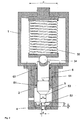
- FIG. 1 and FIG. 2 show two different embodiments of a constant pressure nozzle.
- This consists essentially of a two-part housing, comprising a first or upper housing part 1 and a second or lower housing part 2, the mechanical control unit 31, 32, the nozzle plate 4 and the nozzle needle 5, which in turn is guided in a capsule 6, which in turn is installed in the second or lower housing part 2.
- the nozzle needle 5 could also be performed directly in the housing 2.
- the nozzle needle 5 consists essentially of the nozzle shaft 51 and the nozzle journal 52, which are arranged concentrically with each other. As a rule, a further offset cylindrical region 53 is present between the cylindrical nozzle shaft and the nozzle journal, the front end of which acts as a metallic sealing surface.
- the ratio of the diameter d 1 to the shaft diameter d 2 is decisive for how great the pressure increase during opening, since the pressure initially acts only on the difference of the two diameters associated surfaces.
- the nozzle shaft 51 and consequently the entire nozzle needle 5 are axially guided in a capsule 6.
- a double seal 61, 62 is installed, which is advantageously carried out as low friction.
- the nozzle journal 52 is located on the side facing the nozzle plate 4, so that it forms with this a variable annular gap whose cross-sectional area changes depending on the axial position of the nozzle needle 5.
- the nozzle shaft 51 is spherical.
- the mechanical control unit consists in FIG. 1 from a bellows 31 with an inflow opening 33 for the control medium (eg oil or air) on the Nozzle needle 5 side facing away.
- a connection plate which has on the nozzle shaft 51 side facing the spherical cap of the nozzle shaft 51 matching concave cavity which form fit the spherical cap of the nozzle shaft 51 so that the spring system at the Nozzle shaft facing side is centric fixed to the nozzle shaft 51.
- FIG. 2 shows a variant of a non-inventive nozzle with a compression spring 32 as a flexible control. Furthermore, the power transmission of the compression spring 32 to the nozzle shaft in this case via a separate ball 34th
Landscapes
- Engineering & Computer Science (AREA)
- Mechanical Engineering (AREA)
- General Engineering & Computer Science (AREA)
- Processing And Handling Of Plastics And Other Materials For Molding In General (AREA)
- Coating Apparatus (AREA)
Claims (10)
- Buse de pression constante destinée à la vaporisation d'un composant réactionnel à base de polyuréthane dans la chambre de mélange d'une tête de mélange haute pression, contenant- une ouverture d'entrée pour l'alimentation du composant réactionnel dans la buse de pression constante, la buse de pression constante pouvant être connectée hydrauliquement par le biais de l'ouverture d'entrée à une unité de dosage pour refouler le composant réactionnel, et- une ouverture circulaire de sortie hors de la buse de pression constante, laquelle débouche dans la chambre de mélange et présente un diamètre intérieur de buse d, et- un boîtier de buse (1, 2) et- un pointeau de buse (5) déplaçable axialement à l'intérieur du boîtier de buse (1, 2) et guidé concentriquement par rapport à l'ouverture de sortie débouchant dans la chambre de mélange, lequel pointeau de buse contient une tige de buse (51) et un tourillon de buse (52), qui, dans l'état fermé, ferme l'ouverture de sortie vers la chambre de mélange et qui, dans l'état ouvert, constitue avec l'ouverture de sortie débouchant dans la chambre de mélange un interstice annulaire variable, et- une unité de commande mécanique contenant un élément de commande flexible (31, 32) qui génère une force ajustable, essentiellement axiale, sur le pointeau de buse (5),l'élément de commande flexible (31, 32) contenant un soufflet qui est connecté à un espace de gaz soumis à une pression ajustable, de telle sorte que la force agissant par le biais de l'élément de commande flexible sur le pointeau de buse puisse être réglée pneumatiquement, caractérisée en ce que l'espace dans lequel se déplace l'élément de commande flexible est étanchéifié hydrauliquement par rapport à l'espace connecté hydrauliquement à l'unité de dosage.
- Buse de pression constante selon la revendication 1, caractérisée en ce que l'élément de commande flexible contient en outre un ressort de pression.
- Buse de pression constante selon la revendication 1 ou 2, caractérisée en ce que l'élément de commande flexible (31, 32) n'est pas guidé axialement, et en ce que le côté frontal de l'unité de commande tourné vers le pointeau de buse est supporté sphériquement par rapport au pointeau de buse, le centre du support sur palier sphérique étant situé sur l'axe médian du pointeau de buse mobile, de telle sorte que la surface d'appui de l'unité de commande soit disposée de manière à pouvoir tourner librement autour de ce centre.
- Buse de pression constante selon l'une quelconque des revendications 1 à 3, caractérisée en ce que le diamètre de l'élément de commande flexible est supérieur au diamètre d2 de la tige de buse et en ce que la surface en section transversale de l'interstice annulaire A varie en fonction de la course du tourillon de buse h, le gradient de cette variation δA/δh dans la région d'action principale de la buse étant supérieur à 1,5 * d, de préférence supérieur à 2 * d, et de manière particulièrement préférée à 2,5 * d, la région d'action principale étant définie en ce que la surface en section transversale de la section transversale d'interstice annulaire la plus étroite A dans cette région est définie par la relation mathématique 0,1 * π/4 * d2 ≤ A ≤ 2 * π/4 * d2.
- Buse de pression constante selon l'une quelconque des revendications 1 à 4, caractérisée en ce que le diamètre de la tige de buse est au moins deux fois plus grand, de préférence au moins 2,5 fois plus grand que le diamètre intérieur de la buse d.
- Buse de pression constante selon l'une quelconque des revendications 1 à 5, caractérisée en ce que le diamètre D du soufflet est supérieur au diamètre d2 de la tige de buse d'au moins un facteur 3, de préférence d'un facteur 4.
- Buse de pression constante selon l'une quelconque des revendications 1 à 6, caractérisée en ce que la course maximale de la buse hmax est limitée en fonction du diamètre intérieur de la buse d par la relation hmax = KHub * d, le facteur KHub étant compris dans une plage de 0,15 à 1,5.
- Buse de pression constante selon l'une quelconque des revendications 1 à 7, caractérisée en ce que le soufflet, dans l'état sans charge, adopte une position intermédiaire entre l'état fermé et l'état ouvert au maximum.
- Buse de pression constante selon l'une quelconque des revendications 1 à 8, caractérisée en ce que le pointeau de buse présente un tourillon cylindrique ayant une longueur de 0,3 * d à 1,5 * d.
- Procédé de mélange d'au moins deux composants réactionnels, les au moins deux composants réactionnels étant injectés par le biais de buses dans une chambre de mélange et s'y mélangeant l'un à l'autre, caractérisé en ce qu'au moins l'un des composants réactionnels est injecté dans la chambre de mélange au moyen d'une buse de pression constante selon l'une quelconque des revendications 1 à 9.
Applications Claiming Priority (1)
| Application Number | Priority Date | Filing Date | Title |
|---|---|---|---|
| DE102007037780A DE102007037780A1 (de) | 2007-08-10 | 2007-08-10 | Konstantdruckdüse |
Publications (3)
| Publication Number | Publication Date |
|---|---|
| EP2023025A2 EP2023025A2 (fr) | 2009-02-11 |
| EP2023025A3 EP2023025A3 (fr) | 2013-05-29 |
| EP2023025B1 true EP2023025B1 (fr) | 2014-02-26 |
Family
ID=39967676
Family Applications (1)
| Application Number | Title | Priority Date | Filing Date |
|---|---|---|---|
| EP08013219.4A Active EP2023025B1 (fr) | 2007-08-10 | 2008-07-23 | Buse de pression constante et procédé de mélange avec celle-ci |
Country Status (2)
| Country | Link |
|---|---|
| EP (1) | EP2023025B1 (fr) |
| DE (1) | DE102007037780A1 (fr) |
Families Citing this family (18)
| Publication number | Priority date | Publication date | Assignee | Title |
|---|---|---|---|---|
| IT1399743B1 (it) | 2010-03-15 | 2013-05-03 | Afros Spa | Metodo e apparecchiatura per l'erogazione di una miscela poliuretanica in corpi cavi. |
| DE102010043329A1 (de) * | 2010-11-03 | 2012-05-03 | Bayer Materialscience Aktiengesellschaft | Verfahren zur Herstellung von geschäumten Formkörpern |
| RU2461757C1 (ru) * | 2011-01-12 | 2012-09-20 | Федеральное Государственное Унитарное Предприятие "Государственный научно-производственный ракетно-космический центр "ЦСКБ-Прогресс" (ФГУП "ГНПРКЦ "ЦСКБ-Прогресс") | Клапан управляемый |
| DE102012106084A1 (de) | 2012-07-06 | 2014-01-09 | Kraussmaffei Technologies Gmbh | Komponentenzufuhrdüse |
| DE102012106230A1 (de) | 2012-07-11 | 2014-05-15 | Kraussmaffei Technologies Gmbh | Komponentenzufuhrdüse |
| CN104633193B (zh) * | 2014-12-16 | 2017-08-15 | 太原航空仪表有限公司 | 一种实现水气隔离且压差恒定的压力调节器 |
| AT517391B1 (de) | 2015-07-03 | 2018-11-15 | Sonderhoff Eng Gmbh | Ventileinrichtung |
| DE102018104209C5 (de) | 2018-02-23 | 2023-11-30 | Hennecke Gmbh | Komponentenmischdüse |
| DE102018105447A1 (de) * | 2018-03-09 | 2019-09-12 | Polyplan-GmbH Polyurethan-Maschinen | Injektionsdüse, Mischkopf, sowie Vorrichtung und Verfahren zur Regelung des Austragsdrucks |
| IT202100012113A1 (it) * | 2021-05-11 | 2022-11-11 | Afros Spa | Dispositivo-iniettore per un'apparecchiatura idonea alla miscelazione di componenti chimicamente reattivi |
| CN114289202B (zh) * | 2021-12-01 | 2025-02-18 | 中国船舶集团有限公司第七一一研究所 | 一种喷孔截面积可自调节的机械雾化喷嘴 |
| CN116378860B (zh) * | 2022-12-05 | 2025-06-06 | 中国船舶集团有限公司第七一一研究所 | 喷射阀、发动机以及压力平衡方法 |
| DE102023100258A1 (de) | 2023-01-06 | 2024-07-11 | Hennecke Gmbh | Verfahren und Vorrichtung zur kontinuierlichen Produktion von Polyurethan-Blockschaum |
| PL450305A1 (pl) * | 2024-11-18 | 2026-05-25 | Instytut Maszyn Przepływowych Im. Roberta Szewalskiego Polskiej Akademii Nauk | Urządzenie mieszająco-dozujące płyny w przepływie z napędem płynowym |
| PL450304A1 (pl) * | 2024-11-18 | 2026-05-25 | Instytut Maszyn Przepływowych Im. Roberta Szewalskiego Polskiej Akademii Nauk | Elektromagnetyczno-płynowe urządzenie mieszająco-dozujące płyny w przepływie |
| PL450301A1 (pl) * | 2024-11-18 | 2026-05-25 | Instytut Maszyn Przepływowych Im. Roberta Szewalskiego Polskiej Akademii Nauk | Podatno-płynowe urządzenie mieszająco-dozujące płyny w przepływie |
| PL450303A1 (pl) * | 2024-11-18 | 2026-05-25 | Instytut Maszyn Przepływowych Im. Roberta Szewalskiego Polskiej Akademii Nauk | Elektromagnetyczne urządzenie mieszająco-dozujące płyny w przepływie |
| PL450302A1 (pl) * | 2024-11-18 | 2026-05-25 | Instytut Maszyn Przepływowych Im. Roberta Szewalskiego Polskiej Akademii Nauk | Elektromagnetyczno-podatne urządzenie mieszająco-dozujące płyny w przepływie |
Family Cites Families (6)
| Publication number | Priority date | Publication date | Assignee | Title |
|---|---|---|---|---|
| AT323402B (de) | 1972-12-07 | 1975-07-10 | Lupert Rosemarie | Einrichtung zum verarbeiten von mehrkomponenten-kunststoffen |
| IT1135030B (it) | 1981-01-14 | 1986-08-20 | Afros Spa | Iniettore telecomandato per teste miscelatrici di componenti chimici da alimentare ad uno stampo |
| DE3431112A1 (de) * | 1984-08-24 | 1986-03-06 | Spühl AG, St. Gallen | Mischkopf zur reaktiven mischung von kunststoff-komponenten |
| DE3940866C2 (de) * | 1989-12-11 | 2001-10-25 | Volker Michael | Kreislaufblock für Mischköpfe, insbesondere Paralleldüsenköpfe, für eine Polyurethanschäumanlage |
| ATE255994T1 (de) * | 2000-01-20 | 2003-12-15 | Krauss Maffei Kunststofftech | Injektionsdüse für mischköpfe von reaktionsgiessmaschinen |
| DE10020157A1 (de) | 2000-04-25 | 2001-11-08 | Hennecke Gmbh | Vorrichtung zum Herstellen eines Massivstoff oder Schaumstoff bildenden Reaktionsgemisches aus mindestens zwei fließfähigen Reaktionskomponenten und gegebenenfalls Zusatzkomponenten |
-
2007
- 2007-08-10 DE DE102007037780A patent/DE102007037780A1/de not_active Withdrawn
-
2008
- 2008-07-23 EP EP08013219.4A patent/EP2023025B1/fr active Active
Also Published As
| Publication number | Publication date |
|---|---|
| EP2023025A3 (fr) | 2013-05-29 |
| DE102007037780A1 (de) | 2009-02-12 |
| EP2023025A2 (fr) | 2009-02-11 |
Similar Documents
| Publication | Publication Date | Title |
|---|---|---|
| EP2023025A2 (fr) | Buse de pression constante et procédé de mélange avec celle-ci | |
| DE112017002483B4 (de) | Hydraulischer puffer und mit demselben kombinierter zylinder | |
| DE19930868B4 (de) | Volumenstromregelventil | |
| EP4019802B1 (fr) | Agencement de soupape pour un amortisseur de vibrations | |
| DE3307582C2 (de) | Ventilanordnung zur Steuerung eines aus Pumpe und Motor bestehenden hydrostatischen Antriebs oder Getriebes | |
| AT505439A1 (de) | Exzenterpumpe | |
| DE4027021A1 (de) | Hydraulisch betriebene schlagdrehbohrvorrichtung, insbesondere zum ankerlochbohren | |
| EP4086491B1 (fr) | Agencement de soupape | |
| EP2598758B1 (fr) | Entraînement pneumatique | |
| EP0096303A1 (fr) | Limiteur de pression | |
| DE102004003318A1 (de) | Gleitanordnung für ein Schaftelement mit verbesserter Abriebswiderstansfähigkeit und Injektor | |
| DE19706075C2 (de) | Kolben für eine hydrostatische Maschine | |
| DE69400583T2 (de) | Regler für eine Pumpe mit veränderlicher Förderleistung | |
| DE102009005768B4 (de) | Druckregelung einer hydraulischen Antriebseinheit | |
| EP1502027B1 (fr) | Dispositif de regulation comprenant une soupape de regulation de valeur limite | |
| DE3690299C1 (de) | Steuerventil | |
| DE19951417A1 (de) | Ventilkolben und damit ausgestattetes Ventil | |
| DE102018104209B3 (de) | Komponentenmischdüse | |
| EP1706222A1 (fr) | Procede permettant d'ajuster la position d'un mandrin d'une extrudeuse pour produire des profiles creux | |
| DE10341331B3 (de) | Leistungsregelvorrichtung | |
| DE102022103492B4 (de) | Drosselventilanordnung für hydrostatische einheiten | |
| DE102005052755A1 (de) | Hydraulisch betätigte Klemmeinheit und damit ausgeführte hydraulische Regelachse | |
| AT3212U1 (de) | Radialkolbenpumpe | |
| DE2104362A1 (de) | Druckventil fuer hydraulische anlagen | |
| DE2215450C3 (de) | Freistrahl-Servoventil |
Legal Events
| Date | Code | Title | Description |
|---|---|---|---|
| PUAI | Public reference made under article 153(3) epc to a published international application that has entered the european phase |
Free format text: ORIGINAL CODE: 0009012 |
|
| 17P | Request for examination filed |
Effective date: 20080723 |
|
| AK | Designated contracting states |
Kind code of ref document: A2 Designated state(s): AT BE BG CH CY CZ DE DK EE ES FI FR GB GR HR HU IE IS IT LI LT LU LV MC MT NL NO PL PT RO SE SI SK TR |
|
| AX | Request for extension of the european patent |
Extension state: AL BA MK RS |
|
| PUAL | Search report despatched |
Free format text: ORIGINAL CODE: 0009013 |
|
| AK | Designated contracting states |
Kind code of ref document: A3 Designated state(s): AT BE BG CH CY CZ DE DK EE ES FI FR GB GR HR HU IE IS IT LI LT LU LV MC MT NL NO PL PT RO SE SI SK TR |
|
| AX | Request for extension of the european patent |
Extension state: AL BA MK RS |
|
| RIC1 | Information provided on ipc code assigned before grant |
Ipc: B29B 7/76 20060101ALI20130425BHEP Ipc: B29B 7/80 20060101ALI20130425BHEP Ipc: F16K 31/126 20060101AFI20130425BHEP |
|
| 17Q | First examination report despatched |
Effective date: 20130524 |
|
| GRAP | Despatch of communication of intention to grant a patent |
Free format text: ORIGINAL CODE: EPIDOSNIGR1 |
|
| INTG | Intention to grant announced |
Effective date: 20131016 |
|
| GRAS | Grant fee paid |
Free format text: ORIGINAL CODE: EPIDOSNIGR3 |
|
| GRAA | (expected) grant |
Free format text: ORIGINAL CODE: 0009210 |
|
| AKX | Designation fees paid |
Designated state(s): AT BE BG CH CY CZ DE DK EE ES FI FR GB GR HR HU IE IS IT LI LT LU LV MC MT NL NO PL PT RO SE SI SK TR |
|
| AK | Designated contracting states |
Kind code of ref document: B1 Designated state(s): AT BE BG CH CY CZ DE DK EE ES FI FR GB GR HR HU IE IS IT LI LT LU LV MC MT NL NO PL PT RO SE SI SK TR |
|
| REG | Reference to a national code |
Ref country code: GB Ref legal event code: FG4D Free format text: NOT ENGLISH |
|
| REG | Reference to a national code |
Ref country code: CH Ref legal event code: EP |
|
| REG | Reference to a national code |
Ref country code: AT Ref legal event code: REF Ref document number: 653814 Country of ref document: AT Kind code of ref document: T Effective date: 20140315 |
|
| REG | Reference to a national code |
Ref country code: IE Ref legal event code: FG4D Free format text: LANGUAGE OF EP DOCUMENT: GERMAN |
|
| REG | Reference to a national code |
Ref country code: DE Ref legal event code: R096 Ref document number: 502008011337 Country of ref document: DE Effective date: 20140410 |
|
| REG | Reference to a national code |
Ref country code: CH Ref legal event code: NV Representative=s name: FIAMMENGHI-FIAMMENGHI, CH |
|
| REG | Reference to a national code |
Ref country code: NL Ref legal event code: VDEP Effective date: 20140226 |
|
| REG | Reference to a national code |
Ref country code: LT Ref legal event code: MG4D |
|
| PG25 | Lapsed in a contracting state [announced via postgrant information from national office to epo] |
Ref country code: NO Free format text: LAPSE BECAUSE OF FAILURE TO SUBMIT A TRANSLATION OF THE DESCRIPTION OR TO PAY THE FEE WITHIN THE PRESCRIBED TIME-LIMIT Effective date: 20140526 Ref country code: LT Free format text: LAPSE BECAUSE OF FAILURE TO SUBMIT A TRANSLATION OF THE DESCRIPTION OR TO PAY THE FEE WITHIN THE PRESCRIBED TIME-LIMIT Effective date: 20140226 Ref country code: IS Free format text: LAPSE BECAUSE OF FAILURE TO SUBMIT A TRANSLATION OF THE DESCRIPTION OR TO PAY THE FEE WITHIN THE PRESCRIBED TIME-LIMIT Effective date: 20140626 |
|
| PG25 | Lapsed in a contracting state [announced via postgrant information from national office to epo] |
Ref country code: FI Free format text: LAPSE BECAUSE OF FAILURE TO SUBMIT A TRANSLATION OF THE DESCRIPTION OR TO PAY THE FEE WITHIN THE PRESCRIBED TIME-LIMIT Effective date: 20140226 Ref country code: SE Free format text: LAPSE BECAUSE OF FAILURE TO SUBMIT A TRANSLATION OF THE DESCRIPTION OR TO PAY THE FEE WITHIN THE PRESCRIBED TIME-LIMIT Effective date: 20140226 Ref country code: NL Free format text: LAPSE BECAUSE OF FAILURE TO SUBMIT A TRANSLATION OF THE DESCRIPTION OR TO PAY THE FEE WITHIN THE PRESCRIBED TIME-LIMIT Effective date: 20140226 Ref country code: PT Free format text: LAPSE BECAUSE OF FAILURE TO SUBMIT A TRANSLATION OF THE DESCRIPTION OR TO PAY THE FEE WITHIN THE PRESCRIBED TIME-LIMIT Effective date: 20140626 Ref country code: CY Free format text: LAPSE BECAUSE OF FAILURE TO SUBMIT A TRANSLATION OF THE DESCRIPTION OR TO PAY THE FEE WITHIN THE PRESCRIBED TIME-LIMIT Effective date: 20140226 |
|
| PG25 | Lapsed in a contracting state [announced via postgrant information from national office to epo] |
Ref country code: LV Free format text: LAPSE BECAUSE OF FAILURE TO SUBMIT A TRANSLATION OF THE DESCRIPTION OR TO PAY THE FEE WITHIN THE PRESCRIBED TIME-LIMIT Effective date: 20140226 Ref country code: HR Free format text: LAPSE BECAUSE OF FAILURE TO SUBMIT A TRANSLATION OF THE DESCRIPTION OR TO PAY THE FEE WITHIN THE PRESCRIBED TIME-LIMIT Effective date: 20140226 |
|
| PG25 | Lapsed in a contracting state [announced via postgrant information from national office to epo] |
Ref country code: RO Free format text: LAPSE BECAUSE OF FAILURE TO SUBMIT A TRANSLATION OF THE DESCRIPTION OR TO PAY THE FEE WITHIN THE PRESCRIBED TIME-LIMIT Effective date: 20140226 Ref country code: DK Free format text: LAPSE BECAUSE OF FAILURE TO SUBMIT A TRANSLATION OF THE DESCRIPTION OR TO PAY THE FEE WITHIN THE PRESCRIBED TIME-LIMIT Effective date: 20140226 Ref country code: EE Free format text: LAPSE BECAUSE OF FAILURE TO SUBMIT A TRANSLATION OF THE DESCRIPTION OR TO PAY THE FEE WITHIN THE PRESCRIBED TIME-LIMIT Effective date: 20140226 |
|
| REG | Reference to a national code |
Ref country code: DE Ref legal event code: R097 Ref document number: 502008011337 Country of ref document: DE |
|
| PG25 | Lapsed in a contracting state [announced via postgrant information from national office to epo] |
Ref country code: PL Free format text: LAPSE BECAUSE OF FAILURE TO SUBMIT A TRANSLATION OF THE DESCRIPTION OR TO PAY THE FEE WITHIN THE PRESCRIBED TIME-LIMIT Effective date: 20140226 Ref country code: SK Free format text: LAPSE BECAUSE OF FAILURE TO SUBMIT A TRANSLATION OF THE DESCRIPTION OR TO PAY THE FEE WITHIN THE PRESCRIBED TIME-LIMIT Effective date: 20140226 Ref country code: ES Free format text: LAPSE BECAUSE OF FAILURE TO SUBMIT A TRANSLATION OF THE DESCRIPTION OR TO PAY THE FEE WITHIN THE PRESCRIBED TIME-LIMIT Effective date: 20140226 |
|
| PLBE | No opposition filed within time limit |
Free format text: ORIGINAL CODE: 0009261 |
|
| STAA | Information on the status of an ep patent application or granted ep patent |
Free format text: STATUS: NO OPPOSITION FILED WITHIN TIME LIMIT |
|
| 26N | No opposition filed |
Effective date: 20141127 |
|
| PG25 | Lapsed in a contracting state [announced via postgrant information from national office to epo] |
Ref country code: LU Free format text: LAPSE BECAUSE OF FAILURE TO SUBMIT A TRANSLATION OF THE DESCRIPTION OR TO PAY THE FEE WITHIN THE PRESCRIBED TIME-LIMIT Effective date: 20140723 |
|
| REG | Reference to a national code |
Ref country code: DE Ref legal event code: R097 Ref document number: 502008011337 Country of ref document: DE Effective date: 20141127 |
|
| GBPC | Gb: european patent ceased through non-payment of renewal fee |
Effective date: 20140723 |
|
| REG | Reference to a national code |
Ref country code: IE Ref legal event code: MM4A |
|
| REG | Reference to a national code |
Ref country code: FR Ref legal event code: ST Effective date: 20150331 |
|
| PG25 | Lapsed in a contracting state [announced via postgrant information from national office to epo] |
Ref country code: SI Free format text: LAPSE BECAUSE OF FAILURE TO SUBMIT A TRANSLATION OF THE DESCRIPTION OR TO PAY THE FEE WITHIN THE PRESCRIBED TIME-LIMIT Effective date: 20140226 Ref country code: FR Free format text: LAPSE BECAUSE OF NON-PAYMENT OF DUE FEES Effective date: 20140731 Ref country code: GB Free format text: LAPSE BECAUSE OF NON-PAYMENT OF DUE FEES Effective date: 20140723 |
|
| PG25 | Lapsed in a contracting state [announced via postgrant information from national office to epo] |
Ref country code: IE Free format text: LAPSE BECAUSE OF NON-PAYMENT OF DUE FEES Effective date: 20140723 |
|
| REG | Reference to a national code |
Ref country code: AT Ref legal event code: MM01 Ref document number: 653814 Country of ref document: AT Kind code of ref document: T Effective date: 20140723 |
|
| PG25 | Lapsed in a contracting state [announced via postgrant information from national office to epo] |
Ref country code: AT Free format text: LAPSE BECAUSE OF NON-PAYMENT OF DUE FEES Effective date: 20140723 |
|
| PG25 | Lapsed in a contracting state [announced via postgrant information from national office to epo] |
Ref country code: MC Free format text: LAPSE BECAUSE OF FAILURE TO SUBMIT A TRANSLATION OF THE DESCRIPTION OR TO PAY THE FEE WITHIN THE PRESCRIBED TIME-LIMIT Effective date: 20140226 |
|
| PG25 | Lapsed in a contracting state [announced via postgrant information from national office to epo] |
Ref country code: BG Free format text: LAPSE BECAUSE OF FAILURE TO SUBMIT A TRANSLATION OF THE DESCRIPTION OR TO PAY THE FEE WITHIN THE PRESCRIBED TIME-LIMIT Effective date: 20140226 |
|
| PG25 | Lapsed in a contracting state [announced via postgrant information from national office to epo] |
Ref country code: GR Free format text: LAPSE BECAUSE OF FAILURE TO SUBMIT A TRANSLATION OF THE DESCRIPTION OR TO PAY THE FEE WITHIN THE PRESCRIBED TIME-LIMIT Effective date: 20140527 Ref country code: MT Free format text: LAPSE BECAUSE OF FAILURE TO SUBMIT A TRANSLATION OF THE DESCRIPTION OR TO PAY THE FEE WITHIN THE PRESCRIBED TIME-LIMIT Effective date: 20140226 |
|
| PG25 | Lapsed in a contracting state [announced via postgrant information from national office to epo] |
Ref country code: HU Free format text: LAPSE BECAUSE OF FAILURE TO SUBMIT A TRANSLATION OF THE DESCRIPTION OR TO PAY THE FEE WITHIN THE PRESCRIBED TIME-LIMIT; INVALID AB INITIO Effective date: 20080723 Ref country code: BE Free format text: LAPSE BECAUSE OF FAILURE TO SUBMIT A TRANSLATION OF THE DESCRIPTION OR TO PAY THE FEE WITHIN THE PRESCRIBED TIME-LIMIT Effective date: 20140731 Ref country code: TR Free format text: LAPSE BECAUSE OF FAILURE TO SUBMIT A TRANSLATION OF THE DESCRIPTION OR TO PAY THE FEE WITHIN THE PRESCRIBED TIME-LIMIT Effective date: 20140226 |
|
| PGFP | Annual fee paid to national office [announced via postgrant information from national office to epo] |
Ref country code: DE Payment date: 20250731 Year of fee payment: 18 |
|
| PGFP | Annual fee paid to national office [announced via postgrant information from national office to epo] |
Ref country code: IT Payment date: 20250731 Year of fee payment: 18 |
|
| PGFP | Annual fee paid to national office [announced via postgrant information from national office to epo] |
Ref country code: CH Payment date: 20250801 Year of fee payment: 18 |
|
| PGFP | Annual fee paid to national office [announced via postgrant information from national office to epo] |
Ref country code: CZ Payment date: 20250711 Year of fee payment: 18 |
|
| REG | Reference to a national code |
Ref country code: CH Ref legal event code: U11 Free format text: ST27 STATUS EVENT CODE: U-0-0-U10-U11 (AS PROVIDED BY THE NATIONAL OFFICE) Effective date: 20260801 |