EP2023031A1 - Procédé de fermeture étanche à la pression d'un trou de forage et boîtier sous pression - Google Patents
Procédé de fermeture étanche à la pression d'un trou de forage et boîtier sous pression Download PDFInfo
- Publication number
- EP2023031A1 EP2023031A1 EP08161424A EP08161424A EP2023031A1 EP 2023031 A1 EP2023031 A1 EP 2023031A1 EP 08161424 A EP08161424 A EP 08161424A EP 08161424 A EP08161424 A EP 08161424A EP 2023031 A1 EP2023031 A1 EP 2023031A1
- Authority
- EP
- European Patent Office
- Prior art keywords
- plug
- bore
- undercut
- groove
- tool
- Prior art date
- Legal status (The legal status is an assumption and is not a legal conclusion. Google has not performed a legal analysis and makes no representation as to the accuracy of the status listed.)
- Granted
Links
- 238000000034 method Methods 0.000 title claims abstract description 17
- 238000007789 sealing Methods 0.000 title claims description 8
- 239000000463 material Substances 0.000 claims abstract description 22
- 238000003780 insertion Methods 0.000 claims description 4
- 230000037431 insertion Effects 0.000 claims description 4
- 230000000694 effects Effects 0.000 description 3
- 238000004519 manufacturing process Methods 0.000 description 3
- 239000007779 soft material Substances 0.000 description 3
- 239000000969 carrier Substances 0.000 description 1
- 230000006835 compression Effects 0.000 description 1
- 238000007906 compression Methods 0.000 description 1
- 238000009826 distribution Methods 0.000 description 1
- 238000012423 maintenance Methods 0.000 description 1
- 239000013528 metallic particle Substances 0.000 description 1
- 230000002093 peripheral effect Effects 0.000 description 1
- 238000002360 preparation method Methods 0.000 description 1
- 238000011084 recovery Methods 0.000 description 1
Images
Classifications
-
- F—MECHANICAL ENGINEERING; LIGHTING; HEATING; WEAPONS; BLASTING
- F16—ENGINEERING ELEMENTS AND UNITS; GENERAL MEASURES FOR PRODUCING AND MAINTAINING EFFECTIVE FUNCTIONING OF MACHINES OR INSTALLATIONS; THERMAL INSULATION IN GENERAL
- F16L—PIPES; JOINTS OR FITTINGS FOR PIPES; SUPPORTS FOR PIPES, CABLES OR PROTECTIVE TUBING; MEANS FOR THERMAL INSULATION IN GENERAL
- F16L55/00—Devices or appurtenances for use in, or in connection with, pipes or pipe systems
- F16L55/10—Means for stopping flow in pipes or hoses
- F16L55/12—Means for stopping flow in pipes or hoses by introducing into the pipe a member expandable in situ
- F16L55/128—Means for stopping flow in pipes or hoses by introducing into the pipe a member expandable in situ introduced axially into the pipe or hose
- F16L55/13—Means for stopping flow in pipes or hoses by introducing into the pipe a member expandable in situ introduced axially into the pipe or hose the closure device being a plug fixed by plastic deformation
Definitions
- the invention relates to a method for pressure-tight closure of a bore in housings, comprising the admission of a substantially sleeve-shaped, one-piece plug into the bore of the housing, wherein only the plug is plastically deformed by means of an axial tool, so that the plug over at least part of his Length deformed radially outward and thus brought into sealing connection with the inner wall of the bore, and a pressure housing, with at least one pressure-tight sealed bore, in which a substantially bush-shaped, one-piece plug is inserted, which by plastic deformation an at least partially positive Connection is received with the inner wall of the bore, is held in the inner wall of the bore.
- the object of the present invention is a method and / or a component which, with improved economic production, enables a secure, pressure-tight closing of bores with a system occupying as small a space as possible.
- the method according to the invention is characterized in that prior to insertion of the plug, a circumferential groove and / or undercut is worked out in the bore, and the material of the plug is pressed radially into this groove or behind this undercut substantially.
- a soft material for the plug in comparison with that of the bore in a simple manner, a high pressure resistant and secure sealing and closing action can be achieved.
- a good formable, soft material (as compared to that of the bore) is used for the plug and undesired deformation of the bore is avoided.
- the bore has a substantially shoulder-like cross-sectional constriction to a smaller diameter than the outer diameter of the plug, wherein the plug rests against its radial deformation at this cross-sectional constriction.
- a removable stopper for the stopper may also be introduced into the bore, the stopper placed on this stop and subsequently deformed by means of the tool along the stopper-facing surface of the stopper onto the groove or the drilled hole. Even with this, a secure positioning and the precisely defined deformation of the plug can be ensured.
- a substantially disc-shaped stop member with greater hardness than the stopper inserted into the bore and attached to the cross-sectional constriction after which the stopper attached to the stop member and a portion of the material of the stopper along the surface of the stop member substantially radially in the groove or behind the undercut is pressed, despite a soft and thus easy and economically workable plug for moving within the bore parts a stop can be realized without having to fear damage to the plug and loss of tightness.
- Particularly advantageous and economical is a method in which the plug is produced by cold forming.
- a good centering effect on the distribution of forces along the circumference of the plug or the bore can be achieved in that the tool acts by means of a substantially spherical portion on the jacket region of the plug.
- An initially described pressure housing according to the present invention is characterized in that in the bore a circumferential groove and / or undercut is provided, in which engages the plug with a circumferential projection or which engages behind this peripheral projection of the plug.
- This ensures a well-defined and secure connection and sealing effect between housing and plug, as well such as avoiding unwanted deformation of the housing in the area of the bore.
- This also function holes can be placed closer to the hole to be closed, so that overall a smaller size can be realized.
- a substantially disc-shaped stop member between the stopper and the shoulder-like cross-sectional constriction is additionally provided, wherein the stopper at the stop member at least partially abuts and only the material of the stopper engages in the circumferential groove in the bore or the Undercut the hole engages behind, so it is a safe and the sealing effect not influencing stop for functional parts formed in the pressure housing.
- the disk-shaped abutment part predetermines the final shape of the plug and a flow direction for the material during the forming.
- an economical and simple to manufacture embodiment is given when the plug has been brought by cold forming in its bore-closing mold.
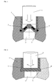
- FIG. 1 a pressure housing in the region of the bore and a plug according to a first embodiment together with the forming tool before the beginning of the forming process
- Fig. 2 is an illustration of the first embodiment in the finished state of the sealed bore
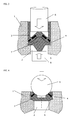
- Fig. 3 shows a second embodiment of bore and plug with additional stop member, also before the beginning of the forming process
- Fig. 4 is an illustration of a third embodiment for the plug and another tool shape.
- a pressure housing for example, a pump carrier or a control block of hydraulic systems, such as for convertible tops, Heckdeckelbetuschisten or the like.
- Application is - as in Fig. 1 shown schematically - a hole 2 worked out, which is to be sealed by a plug 3.
- a circumferential groove 4 is prepared in the inner wall of the bore 2.
- a cross-sectional constriction of the bore 2 may be present, through which a preferably circumferential shoulder 5 is formed.
- the plug 3 is od up to a possibly removable stop, bottom tool.
- the forming of the stopper 3 begins during the further working stroke of the tool.
- a soft material for the stopper 3 preferably softer than the housing 1 in the region of the bore 2
- this can advantageously be achieved by Cold forming done.
- the bottom of the plug 3 is cambered in the direction of the tool or formed in the form of a cone or truncated cone. Also, as a simple and economical production process for the plug 3 is advantageously cold forming used.
- the forward portion 6 of the tool pushes, with continued axial movement, the material of the bottom of the plug 3 forwardly and radially outwardly so that at the forward end of the plug 3, on the side opposite the tool , Under circumferential enlargement forms a radial projection, flows in the material of the plug 3 in the circumferential groove 4 or the otherwise differently shaped recesses in the bore 2.
- This condition with safely closed hole 2 is in Fig. 2 shown schematically.
- the bore 2 is sealed and also absorbed the force resulting from the pressure medium in the interior of the pressure housing 1.
- the physical material properties and the geometry of groove 4, any shoulder 5 and plug 3 are designed so that the material of the plug 3 is deformed with the least effort.
- a substantially disc-shaped stop member 8 is inserted into the bore, which forms a stop for located in the bore functional parts 8.
- This stop member 8 is made of a harder material than the plug 3 and thus protects it from damage by the functional parts 8.
- the stop member 8 but by its the plug 3 facing surface, the flow direction for the material of the plug 3 during the forming precisely defined by the tool 6 and thus provides the desired geometry in the holding area of the plug 3. Also, this can be reduced by the support surface for deforming.
- FIG Figure 4 A further embodiment of a plug 3 according to the invention and a tool provided for this purpose is shown in FIG Figure 4 shown schematically.
- the plug 3 is in this case also in the broadest sense box-shaped, but with a very low coat, which also has radially inwardly tapered surfaces.
- the associated tool has a substantially spherical, with the stopper 3, in particular the tapered surfaces of the shell, cooperating portion 9. Through this section 9 it presses during axial movement - as symbolized by the arrows again - the material from the shell region of the plug 3 in the groove 4, behind a similarly acting undercut or in a plurality of distributed on the inner wall of the bore 2 recesses.
Landscapes
- Engineering & Computer Science (AREA)
- General Engineering & Computer Science (AREA)
- Mechanical Engineering (AREA)
- Pressure Vessels And Lids Thereof (AREA)
Applications Claiming Priority (1)
| Application Number | Priority Date | Filing Date | Title |
|---|---|---|---|
| AT12602007A AT505294B1 (de) | 2007-08-10 | 2007-08-10 | Verfahren zum druckdichten verschliessen einer bohrung, sowie druckgehäuse |
Publications (2)
| Publication Number | Publication Date |
|---|---|
| EP2023031A1 true EP2023031A1 (fr) | 2009-02-11 |
| EP2023031B1 EP2023031B1 (fr) | 2015-04-29 |
Family
ID=40010714
Family Applications (1)
| Application Number | Title | Priority Date | Filing Date |
|---|---|---|---|
| EP20080161424 Ceased EP2023031B1 (fr) | 2007-08-10 | 2008-07-30 | Procédé de fermeture étanche à la pression d'un trou de forage et boîtier sous pression |
Country Status (2)
| Country | Link |
|---|---|
| EP (1) | EP2023031B1 (fr) |
| AT (1) | AT505294B1 (fr) |
Cited By (3)
| Publication number | Priority date | Publication date | Assignee | Title |
|---|---|---|---|---|
| WO2012059116A1 (fr) * | 2010-11-03 | 2012-05-10 | Kvt-Koenig Ag | Élément, de préférence élément de fermeture |
| JP2015515580A (ja) * | 2012-02-01 | 2015-05-28 | エスエフシイ・ケーニッヒ・アーゲー | 構成部品中の孔に挿入するための閉鎖要素 |
| WO2015165780A1 (fr) * | 2014-04-28 | 2015-11-05 | Rheinmetall Waffe Munition Gmbh | Cartouche avec fusible dans le système de propulsion et son procédé de fabrication |
Families Citing this family (2)
| Publication number | Priority date | Publication date | Assignee | Title |
|---|---|---|---|---|
| CN112025356B (zh) * | 2020-08-29 | 2022-06-07 | 中国航发南方工业有限公司 | 一种用于薄壁通孔零件加工的装置 |
| DE102024204566A1 (de) * | 2024-05-17 | 2025-03-13 | Carl Zeiss Smt Gmbh | Monolithischer dichtstopfen und projektionsbelichtungsanlage |
Citations (8)
| Publication number | Priority date | Publication date | Assignee | Title |
|---|---|---|---|---|
| DE538132C (de) * | 1931-11-11 | Robert Bosch Akt Ges | Stopfen zum dichten Abschliessen eines Loches | |
| US3560030A (en) * | 1967-05-11 | 1971-02-02 | Fred Macks | Closures |
| GB1357796A (en) | 1970-07-08 | 1974-06-26 | Koenig Ag Dr Ing | Closing bores |
| EP0364699A2 (fr) | 1988-09-16 | 1990-04-25 | Koenig Verbindungstechnik Ag | Méthode pour obturer de façon étanche un orifice, et orifice obturé |
| EP0443720A2 (fr) | 1990-02-22 | 1991-08-28 | The Lee Company | Bouchon conique d'expansion |
| DE4142153A1 (de) * | 1991-12-20 | 1993-06-24 | Bosch Gmbh Robert | Verschluss fuer druckmittelfuehrende bohrungen oder kanaele in einem gehaeuse |
| DE4343585A1 (de) * | 1993-12-21 | 1995-06-22 | Bosch Gmbh Robert | Gehäuseanordnung und Verfahren zum Verschließen einer Gehäuseöffnung |
| EP0928655A1 (fr) | 1998-01-07 | 1999-07-14 | Metaalgieterij Giesen B.V. | Procédé et bouchon pour rendre étanche un noyau d'une pièce coulée |
Family Cites Families (1)
| Publication number | Priority date | Publication date | Assignee | Title |
|---|---|---|---|---|
| US1801006A (en) * | 1927-12-03 | 1931-04-14 | La Mont Corp | Sealing closure and method of applying same |
-
2007
- 2007-08-10 AT AT12602007A patent/AT505294B1/de not_active IP Right Cessation
-
2008
- 2008-07-30 EP EP20080161424 patent/EP2023031B1/fr not_active Ceased
Patent Citations (8)
| Publication number | Priority date | Publication date | Assignee | Title |
|---|---|---|---|---|
| DE538132C (de) * | 1931-11-11 | Robert Bosch Akt Ges | Stopfen zum dichten Abschliessen eines Loches | |
| US3560030A (en) * | 1967-05-11 | 1971-02-02 | Fred Macks | Closures |
| GB1357796A (en) | 1970-07-08 | 1974-06-26 | Koenig Ag Dr Ing | Closing bores |
| EP0364699A2 (fr) | 1988-09-16 | 1990-04-25 | Koenig Verbindungstechnik Ag | Méthode pour obturer de façon étanche un orifice, et orifice obturé |
| EP0443720A2 (fr) | 1990-02-22 | 1991-08-28 | The Lee Company | Bouchon conique d'expansion |
| DE4142153A1 (de) * | 1991-12-20 | 1993-06-24 | Bosch Gmbh Robert | Verschluss fuer druckmittelfuehrende bohrungen oder kanaele in einem gehaeuse |
| DE4343585A1 (de) * | 1993-12-21 | 1995-06-22 | Bosch Gmbh Robert | Gehäuseanordnung und Verfahren zum Verschließen einer Gehäuseöffnung |
| EP0928655A1 (fr) | 1998-01-07 | 1999-07-14 | Metaalgieterij Giesen B.V. | Procédé et bouchon pour rendre étanche un noyau d'une pièce coulée |
Cited By (10)
| Publication number | Priority date | Publication date | Assignee | Title |
|---|---|---|---|---|
| WO2012059116A1 (fr) * | 2010-11-03 | 2012-05-10 | Kvt-Koenig Ag | Élément, de préférence élément de fermeture |
| CN103261773A (zh) * | 2010-11-03 | 2013-08-21 | Kvt-科尼格股份公司 | 元件、优选闭锁元件 |
| JP2014500829A (ja) * | 2010-11-03 | 2014-01-16 | ケーブイティー−ケーニッヒ・アーゲー | 閉鎖要素 |
| RU2538995C1 (ru) * | 2010-11-03 | 2015-01-10 | Квт-Коениг Аг | Элемент, предпочтительно запирающий элемент |
| US8936168B2 (en) | 2010-11-03 | 2015-01-20 | Kvt-Koenig Ag | Element, preferably a closing element |
| CN103261773B (zh) * | 2010-11-03 | 2015-11-25 | Kvt-科尼格股份公司 | 闭锁元件 |
| JP2015515580A (ja) * | 2012-02-01 | 2015-05-28 | エスエフシイ・ケーニッヒ・アーゲー | 構成部品中の孔に挿入するための閉鎖要素 |
| RU2599439C2 (ru) * | 2012-02-01 | 2016-10-10 | Эс Эф Си КОЕНИГ АГ | Элемент, предпочтительно запорный элемент, для установки в отверстие в детали |
| WO2015165780A1 (fr) * | 2014-04-28 | 2015-11-05 | Rheinmetall Waffe Munition Gmbh | Cartouche avec fusible dans le système de propulsion et son procédé de fabrication |
| US9995563B2 (en) | 2014-04-28 | 2018-06-12 | Rheinmetall Waffe Munition Gmbh | Cartridge with safety fuse in the drive system, and method for producing it |
Also Published As
| Publication number | Publication date |
|---|---|
| AT505294B1 (de) | 2008-12-15 |
| AT505294A4 (de) | 2008-12-15 |
| EP2023031B1 (fr) | 2015-04-29 |
Similar Documents
| Publication | Publication Date | Title |
|---|---|---|
| DE60207431T2 (de) | Lageranordnung und verfahren zum herstellen einer lageranordnung | |
| AT505294B1 (de) | Verfahren zum druckdichten verschliessen einer bohrung, sowie druckgehäuse | |
| DE102014103799B4 (de) | Umformwerkzeug für ein Werkstück und Vorrichtung zum Verformen eines Werkstücks mit einem derartigen Werkzeug | |
| EP2034192A2 (fr) | Bouchon de fermeture | |
| DE3610427C2 (fr) | ||
| DE202006009403U1 (de) | Druckbegrenzungsventil | |
| DE102011007729B3 (de) | Pressscheibe | |
| EP3344431B1 (fr) | Unité à fluide sous pression comportant un boîtier en plastique fabriqué par moulage par injection et procédé pour sa fabrication | |
| DE4306921A1 (de) | Förderpumpe für ein hydraulisches System | |
| DE102014100012A1 (de) | Schlauchkupplung für Hydraulik-Schlauchleitungen mit Umfangsdichtung | |
| EP2906372B1 (fr) | Procédé de fermeture d'une ouverture ménagée dans un actionneur de porte | |
| DE19941577C2 (de) | Rohrverbindung und Verfahren zu ihrer Herstellung | |
| DE19935714B4 (de) | Vorrichtung und Verfahren zum Trennen oder Lochen eines Werkstückes | |
| DE102007007890A1 (de) | Verbindung von einer Innenwelle mit einer Aussenhülse bzw. einer Aussenwelle mit einer Innenhülse | |
| DE102011118587A1 (de) | Zweifach konische Schraubverbindung | |
| DE3120655A1 (de) | Geschlitzter kolbenring und verfahren zu seiner herstellung | |
| EP3514418B1 (fr) | Cartouche de soupape pour un bloc de soupape | |
| EP1622733A2 (fr) | Procede de production d'une piece annulaire en forme de cuvette presentant une denture interieure, preforme en forme de cuvette et piece annulaire en forme de cuvette | |
| DE102004036518A1 (de) | Verdrehsichere Dichtkegelverbindung bei Einspritzleitungen zur Kraftstoffeinspritzung | |
| DE19502014C2 (de) | Verfahren zum Verschrauben von Rohren | |
| EP1507983B1 (fr) | Support destine a recevoir un element de palier et procede de production de ce support | |
| DE10359834B3 (de) | Vorrichtung zum Durchtrennen eines Hohlprofils | |
| DE2612953B2 (de) | Druckbegrenzungsventil für hydraulische Grubenstempel | |
| CH703639A1 (de) | Verfahren zur Umformung eines vorlaufenden Endabschnitts eines Stangenmaterials. | |
| DE2026420A1 (de) | Verfahren zur festen, insbesondere abgedichteten Verbindung eines Hohlkörpers mit einem den Hohlkörper allseitig umschließenden Außenteil |
Legal Events
| Date | Code | Title | Description |
|---|---|---|---|
| PUAI | Public reference made under article 153(3) epc to a published international application that has entered the european phase |
Free format text: ORIGINAL CODE: 0009012 |
|
| AK | Designated contracting states |
Kind code of ref document: A1 Designated state(s): AT BE BG CH CY CZ DE DK EE ES FI FR GB GR HR HU IE IS IT LI LT LU LV MC MT NL NO PL PT RO SE SI SK TR |
|
| AX | Request for extension of the european patent |
Extension state: AL BA MK RS |
|
| 17P | Request for examination filed |
Effective date: 20090320 |
|
| 17Q | First examination report despatched |
Effective date: 20090512 |
|
| AKX | Designation fees paid |
Designated state(s): DE |
|
| RAP1 | Party data changed (applicant data changed or rights of an application transferred) |
Owner name: HOERBIGER AUTOMOTIVE KOMFORTSYSTEME GMBH |
|
| GRAP | Despatch of communication of intention to grant a patent |
Free format text: ORIGINAL CODE: EPIDOSNIGR1 |
|
| INTG | Intention to grant announced |
Effective date: 20141125 |
|
| GRAS | Grant fee paid |
Free format text: ORIGINAL CODE: EPIDOSNIGR3 |
|
| GRAA | (expected) grant |
Free format text: ORIGINAL CODE: 0009210 |
|
| AK | Designated contracting states |
Kind code of ref document: B1 Designated state(s): DE |
|
| REG | Reference to a national code |
Ref country code: DE Ref legal event code: R096 Ref document number: 502008012933 Country of ref document: DE Effective date: 20150603 |
|
| REG | Reference to a national code |
Ref country code: DE Ref legal event code: R097 Ref document number: 502008012933 Country of ref document: DE |
|
| PLBE | No opposition filed within time limit |
Free format text: ORIGINAL CODE: 0009261 |
|
| STAA | Information on the status of an ep patent application or granted ep patent |
Free format text: STATUS: NO OPPOSITION FILED WITHIN TIME LIMIT |
|
| 26N | No opposition filed |
Effective date: 20160201 |
|
| P01 | Opt-out of the competence of the unified patent court (upc) registered |
Effective date: 20230529 |
|
| PGFP | Annual fee paid to national office [announced via postgrant information from national office to epo] |
Ref country code: DE Payment date: 20230926 Year of fee payment: 16 |
|
| REG | Reference to a national code |
Ref country code: DE Ref legal event code: R119 Ref document number: 502008012933 Country of ref document: DE |
|
| PG25 | Lapsed in a contracting state [announced via postgrant information from national office to epo] |
Ref country code: DE Free format text: LAPSE BECAUSE OF NON-PAYMENT OF DUE FEES Effective date: 20250201 |