EP0364699A2 - Méthode pour obturer de façon étanche un orifice, et orifice obturé - Google Patents
Méthode pour obturer de façon étanche un orifice, et orifice obturé Download PDFInfo
- Publication number
- EP0364699A2 EP0364699A2 EP89115620A EP89115620A EP0364699A2 EP 0364699 A2 EP0364699 A2 EP 0364699A2 EP 89115620 A EP89115620 A EP 89115620A EP 89115620 A EP89115620 A EP 89115620A EP 0364699 A2 EP0364699 A2 EP 0364699A2
- Authority
- EP
- European Patent Office
- Prior art keywords
- bore
- stopper
- plug
- arrangement
- preferably according
- Prior art date
- Legal status (The legal status is an assumption and is not a legal conclusion. Google has not performed a legal analysis and makes no representation as to the accuracy of the status listed.)
- Granted
Links
Images





Classifications
-
- F—MECHANICAL ENGINEERING; LIGHTING; HEATING; WEAPONS; BLASTING
- F16—ENGINEERING ELEMENTS AND UNITS; GENERAL MEASURES FOR PRODUCING AND MAINTAINING EFFECTIVE FUNCTIONING OF MACHINES OR INSTALLATIONS; THERMAL INSULATION IN GENERAL
- F16B—DEVICES FOR FASTENING OR SECURING CONSTRUCTIONAL ELEMENTS OR MACHINE PARTS TOGETHER, e.g. NAILS, BOLTS, CIRCLIPS, CLAMPS, CLIPS OR WEDGES; JOINTS OR JOINTING
- F16B13/00—Dowels or other devices fastened in walls or the like by inserting them in holes made therein for that purpose
- F16B13/04—Dowels or other devices fastened in walls or the like by inserting them in holes made therein for that purpose with parts gripping in the hole or behind the reverse side of the wall after inserting from the front
- F16B13/06—Dowels or other devices fastened in walls or the like by inserting them in holes made therein for that purpose with parts gripping in the hole or behind the reverse side of the wall after inserting from the front combined with expanding sleeve
- F16B13/063—Dowels or other devices fastened in walls or the like by inserting them in holes made therein for that purpose with parts gripping in the hole or behind the reverse side of the wall after inserting from the front combined with expanding sleeve by the use of an expander
- F16B13/065—Dowels or other devices fastened in walls or the like by inserting them in holes made therein for that purpose with parts gripping in the hole or behind the reverse side of the wall after inserting from the front combined with expanding sleeve by the use of an expander fastened by extracting the screw, nail or the like
-
- F—MECHANICAL ENGINEERING; LIGHTING; HEATING; WEAPONS; BLASTING
- F16—ENGINEERING ELEMENTS AND UNITS; GENERAL MEASURES FOR PRODUCING AND MAINTAINING EFFECTIVE FUNCTIONING OF MACHINES OR INSTALLATIONS; THERMAL INSULATION IN GENERAL
- F16L—PIPES; JOINTS OR FITTINGS FOR PIPES; SUPPORTS FOR PIPES, CABLES OR PROTECTIVE TUBING; MEANS FOR THERMAL INSULATION IN GENERAL
- F16L55/00—Devices or appurtenances for use in, or in connection with, pipes or pipe systems
- F16L55/10—Means for stopping flow in pipes or hoses
- F16L55/12—Means for stopping flow in pipes or hoses by introducing into the pipe a member expandable in situ
- F16L55/128—Means for stopping flow in pipes or hoses by introducing into the pipe a member expandable in situ introduced axially into the pipe or hose
- F16L55/13—Means for stopping flow in pipes or hoses by introducing into the pipe a member expandable in situ introduced axially into the pipe or hose the closure device being a plug fixed by plastic deformation
-
- F—MECHANICAL ENGINEERING; LIGHTING; HEATING; WEAPONS; BLASTING
- F16—ENGINEERING ELEMENTS AND UNITS; GENERAL MEASURES FOR PRODUCING AND MAINTAINING EFFECTIVE FUNCTIONING OF MACHINES OR INSTALLATIONS; THERMAL INSULATION IN GENERAL
- F16L—PIPES; JOINTS OR FITTINGS FOR PIPES; SUPPORTS FOR PIPES, CABLES OR PROTECTIVE TUBING; MEANS FOR THERMAL INSULATION IN GENERAL
- F16L55/00—Devices or appurtenances for use in, or in connection with, pipes or pipe systems
- F16L55/10—Means for stopping flow in pipes or hoses
- F16L55/12—Means for stopping flow in pipes or hoses by introducing into the pipe a member expandable in situ
- F16L55/128—Means for stopping flow in pipes or hoses by introducing into the pipe a member expandable in situ introduced axially into the pipe or hose
- F16L55/136—Means for stopping flow in pipes or hoses by introducing into the pipe a member expandable in situ introduced axially into the pipe or hose the closure device being a plug fixed by radially expanding or deforming a split ring, hooks or the like
-
- Y—GENERAL TAGGING OF NEW TECHNOLOGICAL DEVELOPMENTS; GENERAL TAGGING OF CROSS-SECTIONAL TECHNOLOGIES SPANNING OVER SEVERAL SECTIONS OF THE IPC; TECHNICAL SUBJECTS COVERED BY FORMER USPC CROSS-REFERENCE ART COLLECTIONS [XRACs] AND DIGESTS
- Y10—TECHNICAL SUBJECTS COVERED BY FORMER USPC
- Y10T—TECHNICAL SUBJECTS COVERED BY FORMER US CLASSIFICATION
- Y10T29/00—Metal working
- Y10T29/49—Method of mechanical manufacture
- Y10T29/49826—Assembling or joining
- Y10T29/49908—Joining by deforming
- Y10T29/49938—Radially expanding part in cavity, aperture, or hollow body
Definitions
- the present invention relates to a method for sealing a bore in a sealed manner, in which a substantially bush-shaped or tubular plug is let into the bore, then the plug wall is radially widened along at least one axial section in order to obtain a tight fit of the plug in the bore and a tight seal closed bore arrangement in which an essentially sleeve-shaped or tubular stopper with a radially spread axial part lies tightly in the bore and a bore or a stopper for the latter arrangement.
- a radial closure of the stopper which is usually made of a metal, such as steel, produces a bore closure which, in particular, should be able to withstand extremely high pressures, for example well above 1,000 bar.
- the construction of such a bore arrangement and the corresponding method for closing a bore by inserting the plug and widening are very simple and enjoy widespread use.
- the technology to which the present invention relates in generic terms starts with closure techniques with rubber-elastic or otherwise elastic sealing members which lie against the wall of the bore or are pressed as part of their elasticity.
- GB-PS 1 530 304 Another technique for closing a hole by means of a rubber-elastic element is known from GB-PS 1 530 304. Further locking techniques are shown in: U.S. Patent 4,301,629, 4,295,578, 4,282,982, 4,254,899, 4,227,625, 4,214,672, 4,083,468, 4,002,516, 3,979,013, 3,895,466, 3,828,968, 3,144 162, Can Pat. 865957, DE-PS 563 474, DE-OS 3 404 187, DE-AS 1 525 720, DE-PS 829 840, DE-OS 3 613 133, DE-PS 2 854 816, DE-OS 2 230 710.
- DE-OS 2 508 269 describes a method in which a solid ball is pressed into a bore, the latter of which is subsequently caulked.
- a plug or plug-like member made of a relatively hard material, such as a metal is radially expanded to achieve the tight fit.
- the problem here is that the tightness of the closure is guaranteed with these procedures, but it cannot be prevented with certainty that the closure element, even if it is sealing, shifts axially in the bore, in particular under high pressure loads. This danger is all the more insidious in that it cannot be determined from a drop in pressure, but only when the closure element, driven by the high pressure in the bore, flies away like a bullet.
- stopper is anchored axially in a form-fitting manner means that the manufacturing tolerances for the stopper and the bore can be relaxed considerably, since they only have to meet the requirements of tightness.
- the positive anchoring in turn clearly does not have to meet the tightness requirements and can therefore be designed specifically for mechanical locking, which is more independent of tolerance.
- a first, extremely simple way of axially locking the plug in the bore is to proceed according to the wording of claim 2.
- a further possibility according to claim 3 is to provide an abutment for the stopper, that is to say to let the stopper into the bore, to spread it there in a sealing manner and then, for example screw an abutment plate into the hole above the stopper, on which the stopper is in contact with its end face pointing out of the hole.
- a simple procedure also results according to claim 5, in that radially resilient parts are provided on the stopper in such a way that when inserted of the stopper into the bore, the latter along the bore wall, pushed in, slide and engage at the predetermined height of the stopper with respect to the bore in correspondingly provided recesses on the bore wall.
- Such spring parts can of course be arranged in several parts on the stopper, for example in the form of resiliently outwardly driven ball locking surfaces or hook locking surfaces, but for reasons of simplification of construction it is preferred to axially slit the sleeve-like stopper wall in one end section and thus to realize radially resilient parts.
- the expansion of the stopper to maintain the seal is now also carried out on the procedure according to the invention to maintain the axial anchorage, by means of an expansion element driven into the stopper, for example a ball or a pin.
- the expansion element usually remains in the stopper, actually belongs to it, and acts practically as an abutment for the seal with respect to the bore wall, it can be seen that if, according to claim 8, it is not the stopper itself but the expansion element on the bore is secured against axial displacement, in this sense indirectly, the stopper is also secured against it, because a pressure load acting out of the bore tends to drive the stopper against the expansion element anchored to the bore.
- a highly simple variant results from the procedure according to claim 9 or 10, according to which the expansion element is screwed into the bore already provided with the plug, the plug is counter-mounted and the screwing in of the expansion element simultaneously expands the plug to maintain the seal, and that driving screwing indirectly results in the axial locking of the stopper via the expansion element.
- the expansion element In order to be able to set the manufacturing tolerance as far as possible with regard to the stopper and expansion element, it is proposed, according to claim 12, to design the expansion element to be hollow on the inside or open on one side in a bell-shaped manner and substantially wider than the sleeve opening of the stopper so that the expansion element can be driven into the stopper .
- a further possibility is to provide abutment surfaces on the stopper and preferably at least in the region of the section to be expanded for the tightness, such as one-piece with the stopper, tips or edged rings, with an abutment surface that is preferably perpendicular to the axis or inclined to the closure load, press into the hole or provide, for example, hardened spring washers with an outer edge in a circular groove on the stopper and press the latter into the softer wall material by spreading to maintain the axial anchoring.
- the proposed method is implemented using an expansion element by pressing this element into the stopper or by pulling it in.
- an opening is provided on the sleeve-like stopper, in the base surface, through which an after-breakable tie rod with a terminal expansion element is passed and the latter is pulled into the stopper.
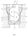
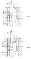
- FIG. 1 shows a bore 1 to be sealed with a mouth 3 against the surroundings and with a loading side 5.
- a plug 7 is inserted into this bore 1 from the mouth side, in a manner to be described, in order to then to be spread radially on a sealing part 9 by plastic deformation of its material against the wall of the bore 1 to obtain a tight fit.
- a locking arrangement 11 is provided, which anchors the plug 7 axially in a form-fitting manner with respect to the bore 1.
- the plug 7 is sleeve-shaped with a coaxial sleeve opening 13.
- a ring notch 17 is provided on the outside of the sleeve wall 15, with a plurality of circular grooves arranged one behind the other or intermediate, toothed in cross-section shapes. In this embodiment variant, these notches 17 form the sealing part 9.
- the locking part 11 comprises, on the one hand, at the bore 1, at a distance from its mouth 3, an internal thread 19 and, on a part 21 of the plug 7 adjoining the bush opening 13, an external thread 23.
- the plug 7 comprises an expansion element 10, here designed as a ball, the diameter of which is somewhat larger than the inside diameter of the sleeve opening 13, in particular at the level of the sealing section 9.
- the illustrated hole 1 is sealed as follows: First, the plug 7 with its External thread 23 is screwed into the internal thread 19 of the bore 1, whereby the axial locking between the plug 7 and the bore 1 is ensured, but by no means a tightness.
- the plug 7 assumes the position shown on the left in this figure.
- the expansion element 10, ie here the ball is then driven into the bushing opening 13 in the direction shown by F until it assumes the position shown on the right in this figure. Characterized the notch 17 is pressed into the material of the wall of bore 1, by plastic expansion of the sleeve wall 15 of the plug 7 and corresponding plastic deformation of the bore wall material. This ensures tightness at the sealing part 9 of the bore arrangement.
- a slot 25 for inserting a screw-in tool is provided on its upper part, in the wall 15 of the sleeve opening 13.
- a differently designed axial locking device can also be provided, such as a bayonet-type locking device, in which an axially designed slot merges into an azimuthally extending slot section, for example incorporated into the bore wall or but on the plug outer wall, and in which, correspondingly on the bore wall or plug outer wall, one or more radially projecting pins are provided which, as is known from such bayonet closures, are first inserted axially along the axial slot, in order then to be screwed azimuthally into the azimuthal slot part will.
- a bayonet-type locking device in which an axially designed slot merges into an azimuthally extending slot section, for example incorporated into the bore wall or but on the plug outer wall, and in which, correspondingly on the bore wall or plug outer wall, one or more radially projecting pins are provided which, as is known from such bayonet closures, are first inserted axially along the axial slot, in order then to be screwed azimuthally into the azi
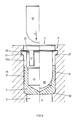
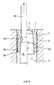
- FIG. 2 The arrangement according to FIG. 2 is basically the same as the one just described, with the difference that here the bush opening 13 extends practically over the entire length of the plug 7.
- the statements made with reference to FIG. 1 apply.
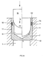
- the stopper 7 is again sleeve-shaped with a sleeve opening 13 over a substantial part of its axial extent.
- the notch 17 on the outside of the sleeve wall 15 of the stopper 7 forms the stopper-side arrangements for creating the tightness on the sealing part 9.
- an annular groove 27 is incorporated according to the invention. This annular groove 27 forms the provision on the bore side for the formation of the locking part 11.
- the expansion element 10 is designed here as a pin with a spherical cap-shaped end 28 and, facing away from the spherical cap 28, has a coaxial truncated cone surface 30.
- Expansion element 10 is driven into the sleeve opening 13 of the stopper 7 in the direction F, which in the manner described, by plastic deformation of the material of the wall 15 and the bore wall, the notch 17, according to the tolerance conditions, is driven into the wall and tightness at the Sealing section 9 is ensured.
- the truncated cone surface 30 finally comes into the region of the end part 15a of the sleeve wall 15.
- the axial extent of the plug is provided that a support shoulder 32 is preferably provided on the bore 1, which prevents slipping Plug 7 is further preferred into the bore 1, dimensioned such that the end portion 15a, when the plug 7 is inserted, lies at the level of the annular groove 27.
- driving in the truncated cone surface 30 causes this end portion 15a to expand radially outward, with which it engages behind the annular groove 27.
- the locking on the locking part 11 is thus created on the one hand by the mentioned annular groove 27 and on the other hand the expanded sleeve wall part 15a.
- the locking part 11 is largely independent of the manufacturing tolerances of the bore 1 and plug 7, and since, as has been explained, creating only tightness at the sealing part 9 is also ensured within wide tolerance limits, the plug as a whole is also used here within wide limits regardless of manufacturing tolerances.
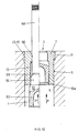
- the embodiment variant according to FIG. 4 proposes that the bore diameter be terminal, i.e. in a lot 33 subsequent to the mouth 3.
- This bore portion 33 with a slightly enlarged diameter has a roughened or profiled wall, is preferably designed as an easy-to-produce thread 35, shown schematically in FIG. 4.
- FIG. 5 A further embodiment is shown in FIG. 5, starting from the embodiment variant according to FIG. 3.
- the upper part of the sleeve wall 15a is slit axially parallel, as shown at 37, with which the stopper 7 is configured like a crown on this side.
- the uppermost part between the slots 37 of remaining spring tabs 43 has projections 39, with a truncated cone surface 41 as a guide surface.
- the expansion element 10 in turn has no truncated cone surface 30 according to FIG. 3, but is cylindrical, with spherical cap 28 as the end.
- the spring tabs 43 formed between the slots 37 with the off projections 39 resiliently stretched radially inwards until the stopper 7 is brought into position, resting on the shoulder 32, in which the spring tabs 43 with the projections 39 snap into the annular groove 27.
- the locking on the locking part 11 is thus created, realized on the one hand by the groove 27, and on the other hand by the spring tabs 43 with projections 39.
- the expansion element is then driven in and drives the notch 17 into the wall of the bore in the manner described.
- the organ 10 with its cylindrical section provides an abutment for the spring tabs 43, which can no longer be moved radially inward, but are held rigidly with their projections 39 in the groove 27.
- the bore 1 is provided with the annular groove 27, as has already been described with reference to FIGS. 3 and 5.
- the stopper 7 does not have a crown with spring tabs 43, but, as in FIG. 3, is designed as a sleeve with the notch 17.
- the lower part of the plug 10 is preferably formed from solid material.
- an abutment element can also be driven here, analogously to FIG. 5, with respect to the spring tabs 43a, but now into the sleeve on the expansion element 10.
- the stopper 7 is configured in the same way as shown for example in FIG. 6.
- the upper section of the bore 1 also has an internal thread 19 here.
- the stopper 7 does not have the corresponding external thread, but the expansion element 10 is enlarged in diameter in its upper part 46 and there has an external thread 23a.
- the actual expanding part of the organ 10 is in turn cylindrical in shape with a spherical cap 28, preferably rotatably mounted on or supported on part 46, as shown at 48.
- the sliding surface between the actual expansion part with spherical cap 28 and propulsion part 46 of the expansion element 10 is preferably made from a pair of materials which is a good one Ensures lubricity even under high pressure, such as with Teflon or ceramic, or is provided with a lubricant.
- the stopper 7 again in the form of a sleeve with a sleeve opening 13, again has the notch 17 for creating tightness on the sealing section 9, and now has slotted and tempered cutting rings 52 embedded in circular grooves 50. These have, radially turned outwards, at least one sharp edge 54 each.
- the spring washers and / or their edges 54 are made from tempered and, simultaneously with the creation of a seal on the sealing part 9, by plastic deformation of the plug wall part in the region of the circular grooves 50 consequently hard material, driven into the wall material of the bore 1, whereby the mechanical, axial locking on the locking part 11 is ensured.
- FIG. 9 shows a preferred embodiment variant of the bore arrangement or the creation of the tight closure according to the invention. It is largely based on the embodiment variant according to FIG. 3. There was found to be disadvantageous the additional incorporation of the annular groove 27 into the bore wall 1. Similar to the procedure for the embodiment variant of FIG. 4, no annular groove 27 is now machined into the bore 1 here, but instead, as from the driving sequence a) to c) of FIG. 9, the end portion 15a of the sleeve wall 15, formed as a sharp edge, of the plug 7 with the truncated cone surface 30 is driven into the wall material of the bore 1, which results in a barb-shaped engagement of the plug 7 on the wall material.
- This embodiment variant has the advantage that no additional operations, such as thread cutting or roughening according to FIG. 4, are necessary on the bore.
- an expansion element 10 was driven into the stopper 7 from the mouth side 3 when the tightness of the part 9 was created.
- such an expansion element is preferably driven into the stopper by pulling from the loading side 5.
- the following examples show such variants.
- the again plug-shaped plug 7, with its bushing end part 15a directed against the loading side 5, is let into the bore 1. He is inserted to form the locking portion 11 with a portion of increased roughness, such as with an external thread 23, in a corresponding portion, possibly also increased roughness, such as with internal thread 19 of the bore 1, so pressed in during the setting process or screwed in beforehand.
- the plug 7 now has a passage opening 60 in the can bottom part.
- the expansion member 10 comprises a preferably frustoconical, end expansion part 62, followed by a closure part 64 of somewhat reduced diameter for the through bore 60 and then, via a predetermined breaking point 66, a tie rod 68.
- the tie rod 68 is passed through the opening 60 and that Expansion organ 10 by train in the direction F 'drawn into the sleeve 13 on the plug 7, whereby its wall, if necessary roughened, is pressed radially against the roughened bore wall to form the sealing part 9.
- the locking part 11 is by interlocking the two threads 19 and 23 formed.
- the tie rod 68 is cut off at the predetermined breaking point 66. Particularly in the case of these embodiments, where the expansion member is retracted, it may be desirable to make the expansion part 62 hollow in order to pull the expansion member into the sleeve 13 of the stopper with uniform cold deformation.
- the plug 7 is largely designed as a tube stub with an inner surface 70 that tapers in a conical manner at most.
- opposite, end portions of the plug 7 are provided, on the outer wall of which tines are provided, preferably annular ribs 72 with sharp edges that are harder than the wall material of the hole.
- the expansion member 10 in turn has the tie rod 68 with the predetermined breaking point 66 and then an actual expansion part 62 widening in the shape of a truncated cone, to which a larger-diameter driving part 74 now adjoins.
- the frustoconical expansion part 62 enters the conically tapered inner bore of the plug 7 and presses the outer wall of the plug on an axially extended section 7 on the wall of the bore 1, whereby 9 tightness is achieved in the sealing area. At most, a corresponding roughening of the outer surface of the plug 7 or the inner wall of the bore 1 is carried out.
- the expansion part 74 lies in the lower section of the inner surface 70 of the plug 7 and, by means of a wedge effect, has driven the coated ribs 72 into the wall material to form the locking part 11. It is preferred, as shown at 76, to slit the lower part of the plug 7 with the tempered ribs, as a result of which the possible expansion stroke of this section to form the locking device 11 is substantially increased.
- the locking area 11 is arranged on the mouth side with ribs or projections 72 on a preferably also slotted mouth-side end part of the stopper 7, as indicated at 76.
- the ribs or projections are 72 harder than the material of the bore wall.
- the expansion part 10 is now arranged next to the predetermined breaking point 66, the expansion part 74, which drives the tempered ribs into the wall material when the expansion element 10 is pulled in, and then follows the actual expansion part 62, which seals the outer wall of the stopper 7 to the wall the hole 1 pressed.
- the preferably wedge-shaped shape of the expansion element 10 causes, as already in the embodiment according to FIGS.
- the stopper 7 in turn has tube-stubby shapes, preferably with an inner surface 70 tapering in the shape of a truncated cone.
- the stopper 7 On its outer wall it has coaxial ring teeth, with tooth flanks 78 which extend the end of the stopper 7 with an enlarged inner bore, ie the Load side 5, are facing, against which the other plug end is inclined, the other tooth flanks 80 are perpendicular to the arrangement axis A or are inclined in the same sense as the flanks 78.
- the tooth flanks 80 create abutment surfaces which, when the expansion element 10 is driven in, engage like barbs in the wall material, while the tightness is ensured by the flanks 78 of the toothing facing the load side 5.
- This division of an intended ring toothing into toothing sealing flanks 78 and toothing locking flanks 80 in turn ensures that even with tolerance-related, slight driving of the toothing into the hole wall, a secure mechanical hold of the plug 7 in the hole 1 is also ensured; the tightness is already ensured, in particular, by the sealing flanks 78 with little intervention.
- slots 82 can also be provided in the lower part of the plug 7, which then acts as a mechanical lock alone.
Landscapes
- Engineering & Computer Science (AREA)
- General Engineering & Computer Science (AREA)
- Mechanical Engineering (AREA)
- Pressure Vessels And Lids Thereof (AREA)
- Dowels (AREA)
- Electrical Discharge Machining, Electrochemical Machining, And Combined Machining (AREA)
- Structures Or Materials For Encapsulating Or Coating Semiconductor Devices Or Solid State Devices (AREA)
- Control And Other Processes For Unpacking Of Materials (AREA)
- Containers And Packaging Bodies Having A Special Means To Remove Contents (AREA)
- Pistons, Piston Rings, And Cylinders (AREA)
- Connector Housings Or Holding Contact Members (AREA)
Applications Claiming Priority (2)
| Application Number | Priority Date | Filing Date | Title |
|---|---|---|---|
| DE3831523A DE3831523A1 (de) | 1988-09-16 | 1988-09-16 | Verfahren zum dichten verschliessen einer bohrung |
| DE3831523 | 1988-09-16 |
Publications (3)
| Publication Number | Publication Date |
|---|---|
| EP0364699A2 true EP0364699A2 (fr) | 1990-04-25 |
| EP0364699A3 EP0364699A3 (en) | 1990-05-16 |
| EP0364699B1 EP0364699B1 (fr) | 1994-09-07 |
Family
ID=6363095
Family Applications (1)
| Application Number | Title | Priority Date | Filing Date |
|---|---|---|---|
| EP89115620A Expired - Lifetime EP0364699B1 (fr) | 1988-09-16 | 1989-08-24 | Méthode pour obturer de façon étanche un orifice, et orifice obturé |
Country Status (7)
| Country | Link |
|---|---|
| US (1) | US5078294A (fr) |
| EP (1) | EP0364699B1 (fr) |
| JP (1) | JPH02180384A (fr) |
| AT (1) | ATE111199T1 (fr) |
| DE (2) | DE3831523A1 (fr) |
| ES (1) | ES2058424T3 (fr) |
| GB (1) | GB2223818B (fr) |
Cited By (8)
| Publication number | Priority date | Publication date | Assignee | Title |
|---|---|---|---|---|
| EP2000731A1 (fr) * | 2007-06-07 | 2008-12-10 | Karlheinz Krüger | Obturateur et procédé pour obturer des perçages d'une façon étanche |
| WO2009000337A1 (fr) | 2007-06-22 | 2008-12-31 | Koenig Verbindungstechnik Ag | Élément de fermeture pour alésages |
| EP2023031A1 (fr) | 2007-08-10 | 2009-02-11 | Hoerbiger Automatisierungstechnik Holding GmbH | Procédé de fermeture étanche à la pression d'un trou de forage et boîtier sous pression |
| EP2476896A1 (fr) | 2011-01-13 | 2012-07-18 | Delphi Automotive Systems Luxembourg SA | Agencement d'actionneur à utiliser dans un injecteur de carburant |
| DE102007026413B4 (de) * | 2007-06-06 | 2014-07-10 | Zf Friedrichshafen Ag | Dichtelement mit definierter Blende |
| GB2543853A (en) * | 2015-11-02 | 2017-05-03 | Ford Global Tech Llc | A passage closure plug |
| EP3366970A1 (fr) * | 2017-02-22 | 2018-08-29 | Delavan, Inc. | Bouchon hydraulique |
| WO2022187431A1 (fr) | 2021-03-04 | 2022-09-09 | Est Group, Inc. | Ensemble bouchon |
Families Citing this family (49)
| Publication number | Priority date | Publication date | Assignee | Title |
|---|---|---|---|---|
| US5293905A (en) * | 1992-08-21 | 1994-03-15 | Jaromir Friedrich | Pipeline plug |
| JP2940898B2 (ja) * | 1993-05-14 | 1999-08-25 | 永山電子工業 株式会社 | Tナット |
| JPH06329037A (ja) * | 1993-05-25 | 1994-11-29 | T R W S S J Kk | 舵取装置入力軸とトーションバーとの固定方法及びこれに適するトーションバー |
| US5437310A (en) * | 1994-08-05 | 1995-08-01 | Expando Seal Tools, Inc. | Plug assembly |
| US5717545A (en) * | 1994-11-03 | 1998-02-10 | International Business Machines Corporation | Swaging appartus with a tubular boss having axially extending surface irregularities and swaging technique for thin actuator arm assemblies |
| US5779085A (en) * | 1997-03-11 | 1998-07-14 | Gas Research Institute | Expandable pin plug for automated use |
| AUPO894997A0 (en) * | 1997-09-03 | 1997-09-25 | Bishop Steering Pty Limited | Power steering valves |
| DE19859370C1 (de) * | 1998-12-22 | 2000-02-24 | Umformtechnik Und Kraftfahrzeu | Vorrichtung zum dichten Verschließen von druckmittelbeaufschlagten dünnwandigen Hohlräumen |
| US6189718B1 (en) * | 1999-03-31 | 2001-02-20 | The United States Of America As Represented By The Department Of Energy | Fluidtight seal for a container |
| DE19948425B4 (de) * | 1999-05-11 | 2014-08-14 | Continental Teves Ag & Co. Ohg | Verschlußvorrichtung zum Verschließen von Bohrungen in einem Gehäuse |
| JP2000354355A (ja) * | 1999-06-10 | 2000-12-19 | Japan Servo Co Ltd | 孔を有する固体部材と円筒部材との締結構造と締結方法 |
| DE10102452C2 (de) * | 2001-01-15 | 2003-03-13 | Ukm Umformtechnik Und Kraftfah | Vorrichtung zum dichten Verschließen von druckmittelbeaufschlagten Bohrungen |
| US7114900B2 (en) * | 2001-11-09 | 2006-10-03 | Textron Inc. | Push-type rivetless nut plate and method and apparatus for installing same |
| US7059816B2 (en) * | 2001-11-09 | 2006-06-13 | Textron Inc. | Nut plate |
| DE10220620A1 (de) * | 2002-05-08 | 2003-11-27 | Siemens Ag | Verschlussvorrichtung und Verfahren zum dichten Verschließen von Bohrungen |
| DE10243205A1 (de) * | 2002-09-18 | 2004-03-25 | Zf Friedrichshafen Ag | Gesicherte Schraube |
| TWI224042B (en) * | 2003-10-07 | 2004-11-21 | Hou-Fei Hu | Improved apparatus for housing tools |
| US20050191122A1 (en) * | 2004-03-01 | 2005-09-01 | Gethmann Douglas P. | Locking mechanism for a threaded connection |
| US7278480B2 (en) * | 2005-03-31 | 2007-10-09 | Schlumberger Technology Corporation | Apparatus and method for sensing downhole parameters |
| FR2891325B1 (fr) * | 2005-09-28 | 2007-10-26 | Airbus France Sas | Dispositif pour la fixation d'un panneau leger sur un support |
| US7575404B2 (en) * | 2006-11-01 | 2009-08-18 | Sps Technologies, Llc | Nut plate fastener assembly for composite materials |
| GB2443640B (en) * | 2006-11-09 | 2009-02-25 | Textron Fastening Syst Ltd | Sealing Plug |
| JP2008304012A (ja) * | 2007-06-08 | 2008-12-18 | Nsk Ltd | ボールねじ装置 |
| DE102007042997A1 (de) * | 2007-09-10 | 2009-03-12 | Marco Systemanalyse Und Entwicklung Gmbh | Verschlussstopfen |
| US7946440B2 (en) * | 2007-11-13 | 2011-05-24 | Kvt Koenig, Llc | Two-piece expandable sealing plug |
| US7631664B1 (en) * | 2008-09-04 | 2009-12-15 | Tejas Research And Engineering, Lp | Threaded expansion plugs |
| DE102008050390A1 (de) * | 2008-10-02 | 2010-04-08 | Wilhelm Karmann Gmbh | Druckbegrenzungsventil mit zwei Druckanschlüssen |
| DE102009012479B4 (de) * | 2009-03-12 | 2012-05-03 | Sew-Eurodrive Gmbh & Co. Kg | Verbindung einer Welle mit einem Aufnahmeteil |
| WO2012059116A1 (fr) * | 2010-11-03 | 2012-05-10 | Kvt-Koenig Ag | Élément, de préférence élément de fermeture |
| EP2673546B1 (fr) | 2011-02-12 | 2017-03-29 | Sfc Koenig Ag | Élément d'obturation pour les trous sous pression |
| FR2977283B1 (fr) * | 2011-06-28 | 2013-08-30 | Valeo Systemes Dessuyage | Fixation permanente vis |
| DE102012100120A1 (de) * | 2012-01-09 | 2013-07-11 | Scanwill Aps | Verschlusseinrichtung zum Verschließen einer hydraulischen und/oder pneumatischen Bohrung |
| BR112014018949A8 (pt) * | 2012-02-01 | 2017-07-11 | Sfc Koenig Ag | Elemento, preferencialmente um elemento de fechamento para inserir em um furo em um componente |
| KR101717734B1 (ko) * | 2012-09-24 | 2017-03-17 | 볼보 컨스트럭션 이큅먼트 에이비 | 유,공압용 실린더의 피스톤 풀림방지 코킹 방법 |
| DE102012019849B4 (de) | 2012-10-10 | 2023-11-02 | Böllhoff Verbindungstechnik GmbH | Bauteil mit Dichtstopfen sowie Verfahren zum Einformen eines Bauteileinsatzes |
| CN103867718A (zh) * | 2012-12-07 | 2014-06-18 | 宁波市鄞州通用电器二厂 | 一种球涨式高压堵头 |
| DE102013202583B3 (de) | 2013-02-18 | 2014-07-03 | Böllhoff Verbindungstechnik GmbH | Reibschweißelement, Gehäuse und Verbindungsverfahren für das Reibschweißelement mit einem Gehäuse |
| US9056370B1 (en) * | 2013-10-01 | 2015-06-16 | The Boeing Company | Friction stir weld plugs and methods of using thereof |
| FR3012564B1 (fr) * | 2013-10-30 | 2015-12-18 | Dassault Aviat | Dispositif et procede d'obturation d'une extremite d'un conduit |
| RU2017103997A (ru) | 2014-07-18 | 2018-08-20 | Эс Эф Си КОЕНИГ АГ | Запорный элемент |
| GB2529913B (en) * | 2014-09-05 | 2019-12-04 | Hubei Boshilong Technology Co Ltd | Closed rivet plug |
| JP5936295B1 (ja) * | 2015-10-26 | 2016-06-22 | 株式会社セラタ | 陳列棚の組付構造及びその構成部材 |
| CN105864429A (zh) * | 2016-05-30 | 2016-08-17 | 浙江万里扬股份有限公司 | 密封塞及工件的密封结构 |
| EP3312105B1 (fr) * | 2016-10-21 | 2022-10-19 | Collins Engine Nozzles, Inc. | Bouchon hydraulique |
| EP3477180B1 (fr) * | 2017-10-28 | 2021-04-14 | Hamilton Sundstrand Corporation | Bouchon hydraulique |
| DE102019200467A1 (de) | 2019-01-16 | 2020-07-16 | Robert Bosch Gmbh | Ventil mit expandierendem Dichtelement |
| US12553562B2 (en) * | 2022-03-10 | 2026-02-17 | The Lee Company | Insert with diametral locking feature and indication feature for installation and method of installation thereof |
| EP4345357B1 (fr) | 2022-09-28 | 2025-11-05 | Sfc Koenig Ag | Dispositif de fermeture pour étancher un trou |
| US20240175647A1 (en) * | 2022-11-30 | 2024-05-30 | Saudi Arabian Oil Company | Ceramic tube plug |
Family Cites Families (56)
| Publication number | Priority date | Publication date | Assignee | Title |
|---|---|---|---|---|
| CA865957A (en) * | 1971-03-16 | Hi-Shear Corporation | Fluid-sealing fastener | |
| DE7338267U (de) * | 1975-04-30 | Bosch R Gmbh | Verschlußvorrichtung | |
| US1801006A (en) * | 1927-12-03 | 1931-04-14 | La Mont Corp | Sealing closure and method of applying same |
| US2292467A (en) * | 1937-10-22 | 1942-08-11 | Norsell Knut Birger | Means for anchoring pins into metallic members |
| US2466546A (en) * | 1943-02-03 | 1949-04-05 | Scovill Manufacturing Co | Threaded insert |
| US2348589A (en) * | 1943-05-24 | 1944-05-09 | Tennessee Coal Iron And Railro | Fastening means |
| US2424449A (en) * | 1945-11-02 | 1947-07-22 | Gasche Fred | Closure for high-pressure vessels |
| DE829840C (de) * | 1948-07-28 | 1952-01-28 | Gen Motors Corp | Verschluss fuer OEffnungen und Durchlaesse und Vorrichtung zu seiner Handhabung |
| GB1004429A (en) * | 1964-01-14 | 1965-09-15 | Gen Am Transport | Method of producing a strong threaded anchorage in a workpiece and ferrule suitable for use therein |
| US3175455A (en) * | 1961-08-02 | 1965-03-30 | Jettron Products Inc | Anchoring device with expansible wedge elements |
| US3144162A (en) * | 1961-08-14 | 1964-08-11 | Bethlehem Steel Corp | Closure for a pressure vessel |
| BE633165A (fr) * | 1962-06-05 | |||
| US3135414A (en) * | 1962-06-18 | 1964-06-02 | Lee Co | Plug |
| US3279301A (en) * | 1963-12-19 | 1966-10-18 | Fischer Artur | Expansion anchor assembly |
| DE1525720C3 (de) * | 1966-09-02 | 1974-06-12 | Langen & Co, 4000 Duesseldorf | Dichtungsanordnung zum gas- und flüssigkeitsdichten Verschließen von gewindelosen, unter Druck stehenden Bohrungen |
| US3431960A (en) * | 1966-10-10 | 1969-03-11 | Robert Neuschotz | Threaded fastener with deformable anchoring portion |
| US3525365A (en) * | 1966-10-17 | 1970-08-25 | Pneumo Dynamics Corp | Expansion plug |
| US3451583A (en) * | 1968-05-20 | 1969-06-24 | Lee Co | Expandable sealing plug |
| CH503923A (de) * | 1968-11-01 | 1971-02-28 | Koenig Ag Dr Ing | Verfahren und Vorrichtung zum Verschliessen von Bohrungen |
| US3525453A (en) * | 1968-11-07 | 1970-08-25 | Lee Co | Sealing plug assembly |
| CH508828A (de) * | 1970-07-08 | 1971-06-15 | Hirmann Georg | Verfahren zum Verschliessen von Bohrungen in Werkstücken und Stopfen zur Ausführung des Verfahrens |
| NL7109253A (fr) * | 1970-07-08 | 1972-01-11 | ||
| US3828968A (en) * | 1972-03-31 | 1974-08-13 | Rogers Corp | Closure plug |
| DE2230710A1 (de) * | 1972-06-23 | 1974-01-10 | Herion Werke Kg | Verschlusstueck fuer bohrungen und kanaele, insbesondere in hydraulischen geraeten |
| US4034462A (en) * | 1973-01-18 | 1977-07-12 | Hilti Aktiengesellschaft | Method for repairing iron molds |
| US3895466A (en) * | 1974-05-21 | 1975-07-22 | Mms Inc | Sewer line blow-out plug |
| US3979013A (en) * | 1974-09-12 | 1976-09-07 | The United States Of America As Represented By The Secretary Of The Navy | Push plug |
| NL7511223A (nl) * | 1974-09-26 | 1976-03-30 | Cebal Societe Anonyme | Verwijderbare, hermetisch afsluitende inrichting. |
| DE2457407C3 (de) * | 1974-12-05 | 1983-11-17 | Gesellschaft für Hydraulik-Zubehör mbH, 6603 Sulzbach | Verschluß für die Füllöffnung eines Druckbehälters |
| DE2508269C3 (de) * | 1975-02-26 | 1978-10-26 | Integral Hydraulik Langen & Co, 4000 Duesseldorf | Verfahren zum gas- und flüssigkeitsdichten Verschließen von gewindelosen, unter Druck stehenden, in einem aus härtbarem Werkstoff bestehenden Bauteil angebrachten Bohrungen |
| US3998700A (en) * | 1975-08-27 | 1976-12-21 | Leprino Cheese Co. | Culture medium and method of preparing bulk starters for Italian cheese manufacture |
| DE2707337A1 (de) * | 1976-02-26 | 1977-09-01 | Seiko Koki Kk | Friktionskupplung fuer eine uhr |
| US4091841A (en) * | 1976-07-14 | 1978-05-30 | Bertea Corporation | Pressure plug and method |
| DE2632823A1 (de) * | 1976-07-21 | 1978-01-26 | Messer Griesheim Gmbh | Rohrverschluss |
| GB1530304A (en) * | 1976-11-29 | 1978-10-25 | Oxley R | Sealing devices |
| US4083468A (en) * | 1977-05-20 | 1978-04-11 | John Howard Batchelor | Vacuumizing closure for vacuum pack containers |
| DE2744501C2 (de) * | 1977-10-04 | 1984-02-23 | Alfred Teves Gmbh, 6000 Frankfurt | Anordnung zum Verschließen einer druckbeaufschlagbaren Bohrung |
| US4195868A (en) * | 1978-02-17 | 1980-04-01 | The Babcock & Wilcox Company | Tubular closure mechanism |
| GB2020774B (en) * | 1978-05-15 | 1982-07-14 | Girling Ltd | Bore closure means |
| US4214672A (en) * | 1979-02-28 | 1980-07-29 | Hector Peniche | Can stopper |
| US4301629A (en) * | 1979-06-27 | 1981-11-24 | James Cooksey | Hole sealing water-tight plug |
| US4265725A (en) * | 1979-07-20 | 1981-05-05 | C. E. Equipment Co., Inc. | Anode connection |
| US4227625A (en) * | 1979-08-17 | 1980-10-14 | Underwood James L | Sealing lid and sealing lid-container combination |
| US4254899A (en) * | 1979-10-22 | 1981-03-10 | S. C. Johnson & Son, Inc. | Self-aligning aerosol dispensing device |
| US4282982A (en) * | 1980-03-11 | 1981-08-11 | Alfred Nuesslein | Tube closure device |
| US4425943A (en) * | 1980-12-08 | 1984-01-17 | Martin John E | Plug assembly for use in method and apparatus for repairing heat exchangers |
| GB2094928B (en) * | 1981-02-13 | 1984-09-19 | Avdel Ltd | Plug assembly and method of plugging a passage |
| DE3111241A1 (de) * | 1981-03-21 | 1982-09-30 | Stumpp + Kurz Gmbh + Co, 7000 Stuttgart | "innengewindeduebel und werkzeug zu dessen setzen und spreizen" |
| US4481702A (en) * | 1982-09-30 | 1984-11-13 | The Boeing Company | Method of assembling threaded insert bushing within a working material |
| US4436117A (en) * | 1982-12-02 | 1984-03-13 | Martin John E | Leak resistant plug assembly |
| DE3308043C1 (de) * | 1983-03-07 | 1984-08-16 | Daimler-Benz Ag, 7000 Stuttgart | Dichtringanordnung an einem Schraubverschluss |
| DE3404187A1 (de) * | 1984-02-07 | 1985-08-08 | Alfred Teves Gmbh, 6000 Frankfurt | Vorrichtung zum verschliessen eines unter druck setzbaren zylinders |
| EP0172812A1 (fr) * | 1984-03-09 | 1986-03-05 | Expando Seal Tools, Inc. | Montage de bouchon resistant aux fuites |
| DE3419999C2 (de) * | 1984-05-29 | 1987-02-12 | Karl 7298 Loßburg Hehl | Rohrverschraubung mit Berührungsdichtung |
| US4925578A (en) * | 1984-11-19 | 1990-05-15 | Shell Oil Company | Polymer-thickened aqueous solutions containing a mercaptobenzothiazole |
| DE3613133A1 (de) * | 1986-04-18 | 1986-09-04 | Mtu Motoren- Und Turbinen-Union Friedrichshafen Gmbh, 88045 Friedrichshafen | Einrichtung zum verschliessen von bohrungen |
-
1988
- 1988-09-16 DE DE3831523A patent/DE3831523A1/de not_active Withdrawn
-
1989
- 1989-08-24 AT AT89115620T patent/ATE111199T1/de not_active IP Right Cessation
- 1989-08-24 DE DE58908313T patent/DE58908313D1/de not_active Expired - Lifetime
- 1989-08-24 ES ES89115620T patent/ES2058424T3/es not_active Expired - Lifetime
- 1989-08-24 EP EP89115620A patent/EP0364699B1/fr not_active Expired - Lifetime
- 1989-09-11 GB GB8920513A patent/GB2223818B/en not_active Expired - Lifetime
- 1989-09-14 JP JP1237368A patent/JPH02180384A/ja active Pending
- 1989-09-15 US US07/409,623 patent/US5078294A/en not_active Expired - Lifetime
Cited By (15)
| Publication number | Priority date | Publication date | Assignee | Title |
|---|---|---|---|---|
| DE102007026413B4 (de) * | 2007-06-06 | 2014-07-10 | Zf Friedrichshafen Ag | Dichtelement mit definierter Blende |
| DE102007027004A1 (de) * | 2007-06-07 | 2008-12-11 | Krüger, Karlheinz | Verschluss und Verfahren zum dichten Verschließen von Bohrungen |
| EP2000731A1 (fr) * | 2007-06-07 | 2008-12-10 | Karlheinz Krüger | Obturateur et procédé pour obturer des perçages d'une façon étanche |
| WO2009000337A1 (fr) | 2007-06-22 | 2008-12-31 | Koenig Verbindungstechnik Ag | Élément de fermeture pour alésages |
| WO2009000559A1 (fr) * | 2007-06-22 | 2008-12-31 | Koenig Verbindungstechnik Ag | Élément de fermeture pour alésages |
| WO2009000317A1 (fr) * | 2007-06-22 | 2008-12-31 | Koenig Verbindungstechnik Ag | Élément de fermeture pour alésages |
| EP2023031A1 (fr) | 2007-08-10 | 2009-02-11 | Hoerbiger Automatisierungstechnik Holding GmbH | Procédé de fermeture étanche à la pression d'un trou de forage et boîtier sous pression |
| EP2476896A1 (fr) | 2011-01-13 | 2012-07-18 | Delphi Automotive Systems Luxembourg SA | Agencement d'actionneur à utiliser dans un injecteur de carburant |
| WO2012095377A1 (fr) | 2011-01-13 | 2012-07-19 | Delphi Automotive Systems Luxembourg Sa | Agencement d'actionneur à utiliser dans un injecteur de carburant |
| GB2543853A (en) * | 2015-11-02 | 2017-05-03 | Ford Global Tech Llc | A passage closure plug |
| GB2543853B (en) * | 2015-11-02 | 2019-10-02 | Ford Global Tech Llc | A passage closure plug |
| EP3366970A1 (fr) * | 2017-02-22 | 2018-08-29 | Delavan, Inc. | Bouchon hydraulique |
| US10746340B2 (en) | 2017-02-22 | 2020-08-18 | Delavan Inc. | Hydraulic plug |
| WO2022187431A1 (fr) | 2021-03-04 | 2022-09-09 | Est Group, Inc. | Ensemble bouchon |
| EP4302009A4 (fr) * | 2021-03-04 | 2025-01-01 | EST Group, Inc. | Ensemble bouchon |
Also Published As
| Publication number | Publication date |
|---|---|
| ES2058424T3 (es) | 1994-11-01 |
| ATE111199T1 (de) | 1994-09-15 |
| GB2223818A (en) | 1990-04-18 |
| DE3831523A1 (de) | 1990-03-22 |
| US5078294A (en) | 1992-01-07 |
| GB8920513D0 (en) | 1989-10-25 |
| DE58908313D1 (de) | 1994-10-13 |
| EP0364699B1 (fr) | 1994-09-07 |
| JPH02180384A (ja) | 1990-07-13 |
| GB2223818B (en) | 1993-02-17 |
| EP0364699A3 (en) | 1990-05-16 |
Similar Documents
| Publication | Publication Date | Title |
|---|---|---|
| EP0364699B1 (fr) | Méthode pour obturer de façon étanche un orifice, et orifice obturé | |
| EP0068227B1 (fr) | Boulon d'ancrage | |
| EP2567107B1 (fr) | Élément d'ancrage extensible et procédé d'ancrage d'un élément d'ancrage extensible | |
| EP3084233B1 (fr) | Cheville à expansion avec sécurité anti-rotation | |
| WO1991011628A1 (fr) | Dispositif d'assemblage rivete | |
| DE1289374B (de) | Rohrverbindungsstueck fuer Hochdruckleitungen | |
| DE1750663B2 (de) | Ankerschraube | |
| DE2113808B2 (de) | Stiftschraube | |
| EP0515916A2 (fr) | Boulon d'ancrage expansible | |
| DE102010060771A1 (de) | Befestigungselement | |
| DE1500891B1 (de) | Befestigungseinsatz fuer Leichtbau-Schichtverbundplatten | |
| DE2545581C2 (de) | Befestigungselement zum Einsetzen in Flachmaterial | |
| EP3374649B1 (fr) | Vis autotaraudeuse | |
| DE102015223473A1 (de) | Buchse, Befestigungselement und Verfahren zum Anordnen eines Befestigungselements an einem Werkstück | |
| WO1993010930A1 (fr) | Dispositif d'accouplement pour outils, presentant un manchon de raccordement pouvant etre elargi radialement de maniere elastique, ainsi qu'une tige avec un element de serrage | |
| WO2004072495A1 (fr) | Systeme d'ancrage a contre-depouille pouvant etre mis en place par liaison de forme | |
| EP0883755A1 (fr) | Cheville a percussion | |
| EP0809553A1 (fr) | Outil expansible pour formage a froid | |
| DE3139174A1 (de) | Ankerbolzen | |
| DE1500923B1 (de) | Spreizbare Bolzenverankerungsvorrichtung | |
| EP0423460B1 (fr) | Cheville expansible | |
| DE3426288C2 (de) | Spreizdübel aus Metallblech | |
| EP2022991B1 (fr) | Cheville, en particulier cheville de radiateur | |
| DE4322589A1 (de) | Spreizdübel | |
| EP0738835A1 (fr) | Cheville à enveloppe en forme de crible |
Legal Events
| Date | Code | Title | Description |
|---|---|---|---|
| PUAI | Public reference made under article 153(3) epc to a published international application that has entered the european phase |
Free format text: ORIGINAL CODE: 0009012 |
|
| PUAL | Search report despatched |
Free format text: ORIGINAL CODE: 0009013 |
|
| AK | Designated contracting states |
Kind code of ref document: A2 Designated state(s): AT BE CH DE ES FR GB GR IT LI LU NL SE |
|
| AK | Designated contracting states |
Kind code of ref document: A3 Designated state(s): AT BE CH DE ES FR GB GR IT LI LU NL SE |
|
| 17P | Request for examination filed |
Effective date: 19900327 |
|
| 17Q | First examination report despatched |
Effective date: 19910403 |
|
| GRAA | (expected) grant |
Free format text: ORIGINAL CODE: 0009210 |
|
| AK | Designated contracting states |
Kind code of ref document: B1 Designated state(s): AT BE CH DE ES FR GB GR IT LI LU NL SE |
|
| PG25 | Lapsed in a contracting state [announced via postgrant information from national office to epo] |
Ref country code: GR Free format text: LAPSE BECAUSE OF FAILURE TO SUBMIT A TRANSLATION OF THE DESCRIPTION OR TO PAY THE FEE WITHIN THE PRESCRIBED TIME-LIMIT Effective date: 19940907 Ref country code: GB Effective date: 19940907 |
|
| REF | Corresponds to: |
Ref document number: 111199 Country of ref document: AT Date of ref document: 19940915 Kind code of ref document: T |
|
| REF | Corresponds to: |
Ref document number: 58908313 Country of ref document: DE Date of ref document: 19941013 |
|
| ET | Fr: translation filed | ||
| REG | Reference to a national code |
Ref country code: ES Ref legal event code: FG2A Ref document number: 2058424 Country of ref document: ES Kind code of ref document: T3 |
|
| ITF | It: translation for a ep patent filed | ||
| PG25 | Lapsed in a contracting state [announced via postgrant information from national office to epo] |
Ref country code: SE Effective date: 19941207 |
|
| GBV | Gb: ep patent (uk) treated as always having been void in accordance with gb section 77(7)/1977 [no translation filed] |
Effective date: 19940907 |
|
| PLBE | No opposition filed within time limit |
Free format text: ORIGINAL CODE: 0009261 |
|
| STAA | Information on the status of an ep patent application or granted ep patent |
Free format text: STATUS: NO OPPOSITION FILED WITHIN TIME LIMIT |
|
| 26N | No opposition filed | ||
| PG25 | Lapsed in a contracting state [announced via postgrant information from national office to epo] |
Ref country code: LU Free format text: LAPSE BECAUSE OF NON-PAYMENT OF DUE FEES Effective date: 19950831 |
|
| PGFP | Annual fee paid to national office [announced via postgrant information from national office to epo] |
Ref country code: NL Payment date: 20080803 Year of fee payment: 20 Ref country code: ES Payment date: 20080922 Year of fee payment: 20 Ref country code: DE Payment date: 20080905 Year of fee payment: 20 |
|
| PGFP | Annual fee paid to national office [announced via postgrant information from national office to epo] |
Ref country code: FR Payment date: 20080818 Year of fee payment: 20 Ref country code: IT Payment date: 20080827 Year of fee payment: 20 Ref country code: AT Payment date: 20080814 Year of fee payment: 20 |
|
| PGFP | Annual fee paid to national office [announced via postgrant information from national office to epo] |
Ref country code: CH Payment date: 20081024 Year of fee payment: 20 |
|
| PGFP | Annual fee paid to national office [announced via postgrant information from national office to epo] |
Ref country code: BE Payment date: 20090119 Year of fee payment: 20 |
|
| BE20 | Be: patent expired |
Owner name: *KOENIG VERBINDUNGSTECHNIK A.G. Effective date: 20090824 |
|
| REG | Reference to a national code |
Ref country code: CH Ref legal event code: PL |
|
| REG | Reference to a national code |
Ref country code: ES Ref legal event code: FD2A Effective date: 20090825 |
|
| NLV7 | Nl: ceased due to reaching the maximum lifetime of a patent |
Effective date: 20090824 |
|
| PG25 | Lapsed in a contracting state [announced via postgrant information from national office to epo] |
Ref country code: NL Free format text: LAPSE BECAUSE OF EXPIRATION OF PROTECTION Effective date: 20090824 |
|
| PG25 | Lapsed in a contracting state [announced via postgrant information from national office to epo] |
Ref country code: ES Free format text: LAPSE BECAUSE OF EXPIRATION OF PROTECTION Effective date: 20090825 |