EP3578295A1 - Dispositif de mesure de position et procédé de fonctionnement d'un dispositif de mesure de position - Google Patents
Dispositif de mesure de position et procédé de fonctionnement d'un dispositif de mesure de position Download PDFInfo
- Publication number
- EP3578295A1 EP3578295A1 EP19163617.4A EP19163617A EP3578295A1 EP 3578295 A1 EP3578295 A1 EP 3578295A1 EP 19163617 A EP19163617 A EP 19163617A EP 3578295 A1 EP3578295 A1 EP 3578295A1
- Authority
- EP
- European Patent Office
- Prior art keywords
- measured values
- collision
- unit
- measuring device
- digital
- Prior art date
- Legal status (The legal status is an assumption and is not a legal conclusion. Google has not performed a legal analysis and makes no representation as to the accuracy of the status listed.)
- Granted
Links
Images


Classifications
-
- G—PHYSICS
- G01—MEASURING; TESTING
- G01D—MEASURING NOT SPECIALLY ADAPTED FOR A SPECIFIC VARIABLE; ARRANGEMENTS FOR MEASURING TWO OR MORE VARIABLES NOT COVERED IN A SINGLE OTHER SUBCLASS; TARIFF METERING APPARATUS; MEASURING OR TESTING NOT OTHERWISE PROVIDED FOR
- G01D5/00—Mechanical means for transferring the output of a sensing member; Means for converting the output of a sensing member to another variable where the form or nature of the sensing member does not constrain the means for converting; Transducers not specially adapted for a specific variable
- G01D5/12—Mechanical means for transferring the output of a sensing member; Means for converting the output of a sensing member to another variable where the form or nature of the sensing member does not constrain the means for converting; Transducers not specially adapted for a specific variable using electric or magnetic means
- G01D5/244—Mechanical means for transferring the output of a sensing member; Means for converting the output of a sensing member to another variable where the form or nature of the sensing member does not constrain the means for converting; Transducers not specially adapted for a specific variable using electric or magnetic means influencing characteristics of pulses or pulse trains; generating pulses or pulse trains
- G01D5/24471—Error correction
- G01D5/24476—Signal processing
-
- G—PHYSICS
- G01—MEASURING; TESTING
- G01D—MEASURING NOT SPECIALLY ADAPTED FOR A SPECIFIC VARIABLE; ARRANGEMENTS FOR MEASURING TWO OR MORE VARIABLES NOT COVERED IN A SINGLE OTHER SUBCLASS; TARIFF METERING APPARATUS; MEASURING OR TESTING NOT OTHERWISE PROVIDED FOR
- G01D3/00—Indicating or recording apparatus with provision for the special purposes referred to in the subgroups
- G01D3/08—Indicating or recording apparatus with provision for the special purposes referred to in the subgroups with provision for safeguarding the apparatus, e.g. against abnormal operation, against breakdown
-
- B—PERFORMING OPERATIONS; TRANSPORTING
- B23—MACHINE TOOLS; METAL-WORKING NOT OTHERWISE PROVIDED FOR
- B23C—MILLING
- B23C9/00—Details or accessories so far as specially adapted to milling machines or cutter
-
- G—PHYSICS
- G01—MEASURING; TESTING
- G01B—MEASURING LENGTH, THICKNESS OR SIMILAR LINEAR DIMENSIONS; MEASURING ANGLES; MEASURING AREAS; MEASURING IRREGULARITIES OF SURFACES OR CONTOURS
- G01B21/00—Measuring arrangements or details thereof, where the measuring technique is not covered by the other groups of this subclass, unspecified or not relevant
-
- G—PHYSICS
- G01—MEASURING; TESTING
- G01D—MEASURING NOT SPECIALLY ADAPTED FOR A SPECIFIC VARIABLE; ARRANGEMENTS FOR MEASURING TWO OR MORE VARIABLES NOT COVERED IN A SINGLE OTHER SUBCLASS; TARIFF METERING APPARATUS; MEASURING OR TESTING NOT OTHERWISE PROVIDED FOR
- G01D5/00—Mechanical means for transferring the output of a sensing member; Means for converting the output of a sensing member to another variable where the form or nature of the sensing member does not constrain the means for converting; Transducers not specially adapted for a specific variable
- G01D5/12—Mechanical means for transferring the output of a sensing member; Means for converting the output of a sensing member to another variable where the form or nature of the sensing member does not constrain the means for converting; Transducers not specially adapted for a specific variable using electric or magnetic means
- G01D5/244—Mechanical means for transferring the output of a sensing member; Means for converting the output of a sensing member to another variable where the form or nature of the sensing member does not constrain the means for converting; Transducers not specially adapted for a specific variable using electric or magnetic means influencing characteristics of pulses or pulse trains; generating pulses or pulse trains
-
- G—PHYSICS
- G01—MEASURING; TESTING
- G01D—MEASURING NOT SPECIALLY ADAPTED FOR A SPECIFIC VARIABLE; ARRANGEMENTS FOR MEASURING TWO OR MORE VARIABLES NOT COVERED IN A SINGLE OTHER SUBCLASS; TARIFF METERING APPARATUS; MEASURING OR TESTING NOT OTHERWISE PROVIDED FOR
- G01D5/00—Mechanical means for transferring the output of a sensing member; Means for converting the output of a sensing member to another variable where the form or nature of the sensing member does not constrain the means for converting; Transducers not specially adapted for a specific variable
- G01D5/12—Mechanical means for transferring the output of a sensing member; Means for converting the output of a sensing member to another variable where the form or nature of the sensing member does not constrain the means for converting; Transducers not specially adapted for a specific variable using electric or magnetic means
- G01D5/244—Mechanical means for transferring the output of a sensing member; Means for converting the output of a sensing member to another variable where the form or nature of the sensing member does not constrain the means for converting; Transducers not specially adapted for a specific variable using electric or magnetic means influencing characteristics of pulses or pulse trains; generating pulses or pulse trains
- G01D5/24457—Failure detection
-
- G—PHYSICS
- G01—MEASURING; TESTING
- G01D—MEASURING NOT SPECIALLY ADAPTED FOR A SPECIFIC VARIABLE; ARRANGEMENTS FOR MEASURING TWO OR MORE VARIABLES NOT COVERED IN A SINGLE OTHER SUBCLASS; TARIFF METERING APPARATUS; MEASURING OR TESTING NOT OTHERWISE PROVIDED FOR
- G01D5/00—Mechanical means for transferring the output of a sensing member; Means for converting the output of a sensing member to another variable where the form or nature of the sensing member does not constrain the means for converting; Transducers not specially adapted for a specific variable
- G01D5/12—Mechanical means for transferring the output of a sensing member; Means for converting the output of a sensing member to another variable where the form or nature of the sensing member does not constrain the means for converting; Transducers not specially adapted for a specific variable using electric or magnetic means
- G01D5/244—Mechanical means for transferring the output of a sensing member; Means for converting the output of a sensing member to another variable where the form or nature of the sensing member does not constrain the means for converting; Transducers not specially adapted for a specific variable using electric or magnetic means influencing characteristics of pulses or pulse trains; generating pulses or pulse trains
- G01D5/248—Mechanical means for transferring the output of a sensing member; Means for converting the output of a sensing member to another variable where the form or nature of the sensing member does not constrain the means for converting; Transducers not specially adapted for a specific variable using electric or magnetic means influencing characteristics of pulses or pulse trains; generating pulses or pulse trains by varying pulse repetition frequency
-
- G—PHYSICS
- G05—CONTROLLING; REGULATING
- G05B—CONTROL OR REGULATING SYSTEMS IN GENERAL; FUNCTIONAL ELEMENTS OF SUCH SYSTEMS; MONITORING OR TESTING ARRANGEMENTS FOR SUCH SYSTEMS OR ELEMENTS
- G05B19/00—Program-control systems
- G05B19/02—Program-control systems electric
- G05B19/18—Numerical control [NC], i.e. automatically operating machines, in particular machine tools, e.g. in a manufacturing environment, so as to execute positioning, movement or co-ordinated operations by means of program data in numerical form
- G05B19/406—Numerical control [NC], i.e. automatically operating machines, in particular machine tools, e.g. in a manufacturing environment, so as to execute positioning, movement or co-ordinated operations by means of program data in numerical form characterised by monitoring or safety
- G05B19/4061—Avoiding collision or forbidden zones
-
- B—PERFORMING OPERATIONS; TRANSPORTING
- B23—MACHINE TOOLS; METAL-WORKING NOT OTHERWISE PROVIDED FOR
- B23Q—DETAILS, COMPONENTS, OR ACCESSORIES FOR MACHINE TOOLS, e.g. ARRANGEMENTS FOR COPYING OR CONTROLLING; MACHINE TOOLS IN GENERAL CHARACTERISED BY THE CONSTRUCTION OF PARTICULAR DETAILS OR COMPONENTS; COMBINATIONS OR ASSOCIATIONS OF METAL-WORKING MACHINES, NOT DIRECTED TO A PARTICULAR RESULT
- B23Q17/00—Arrangements for observing, indicating or measuring on machine tools
- B23Q17/22—Arrangements for observing, indicating or measuring on machine tools for indicating or measuring existing or desired position of tool or work
- B23Q17/2208—Detection or prevention of collisions
-
- G—PHYSICS
- G05—CONTROLLING; REGULATING
- G05B—CONTROL OR REGULATING SYSTEMS IN GENERAL; FUNCTIONAL ELEMENTS OF SUCH SYSTEMS; MONITORING OR TESTING ARRANGEMENTS FOR SUCH SYSTEMS OR ELEMENTS
- G05B19/00—Program-control systems
- G05B19/02—Program-control systems electric
- G05B19/18—Numerical control [NC], i.e. automatically operating machines, in particular machine tools, e.g. in a manufacturing environment, so as to execute positioning, movement or co-ordinated operations by means of program data in numerical form
- G05B19/406—Numerical control [NC], i.e. automatically operating machines, in particular machine tools, e.g. in a manufacturing environment, so as to execute positioning, movement or co-ordinated operations by means of program data in numerical form characterised by monitoring or safety
- G05B19/4062—Monitoring servoloop, e.g. overload of servomotor, loss of feedback or reference
-
- G—PHYSICS
- G05—CONTROLLING; REGULATING
- G05B—CONTROL OR REGULATING SYSTEMS IN GENERAL; FUNCTIONAL ELEMENTS OF SUCH SYSTEMS; MONITORING OR TESTING ARRANGEMENTS FOR SUCH SYSTEMS OR ELEMENTS
- G05B2219/00—Program-control systems
- G05B2219/30—Nc systems
- G05B2219/37—Measurements
- G05B2219/37175—Normal encoder, disk for pulses, incremental
-
- G—PHYSICS
- G05—CONTROLLING; REGULATING
- G05B—CONTROL OR REGULATING SYSTEMS IN GENERAL; FUNCTIONAL ELEMENTS OF SUCH SYSTEMS; MONITORING OR TESTING ARRANGEMENTS FOR SUCH SYSTEMS OR ELEMENTS
- G05B2219/00—Program-control systems
- G05B2219/30—Nc systems
- G05B2219/37—Measurements
- G05B2219/37325—Multisensor integration, fusion, redundant
-
- G—PHYSICS
- G05—CONTROLLING; REGULATING
- G05B—CONTROL OR REGULATING SYSTEMS IN GENERAL; FUNCTIONAL ELEMENTS OF SUCH SYSTEMS; MONITORING OR TESTING ARRANGEMENTS FOR SUCH SYSTEMS OR ELEMENTS
- G05B2219/00—Program-control systems
- G05B2219/30—Nc systems
- G05B2219/37—Measurements
- G05B2219/37388—Acceleration or deceleration, inertial measurement
-
- G—PHYSICS
- G05—CONTROLLING; REGULATING
- G05B—CONTROL OR REGULATING SYSTEMS IN GENERAL; FUNCTIONAL ELEMENTS OF SUCH SYSTEMS; MONITORING OR TESTING ARRANGEMENTS FOR SUCH SYSTEMS OR ELEMENTS
- G05B2219/00—Program-control systems
- G05B2219/30—Nc systems
- G05B2219/37—Measurements
- G05B2219/37624—Detect collision, blocking by measuring change of velocity or torque
Definitions
- the present invention relates to a position measuring device according to claim 1, and a method for operating a position measuring device according to claim 10. More particularly, the invention relates to the detection of collision events in a position-measuring device.
- Rotary encoders or angle encoders measure rotational movements, for example, of rotating shafts.
- Linear encoders measure linear displacements of machine parts arranged movably relative to one another.
- FIG. 1 shows in a simplified manner a motor spindle 10 of a machine tool.
- the central component is a spindle motor 1 with a shaft 2.
- a tool holder 3 for receiving a tool 4 for example, a milling tool
- a position measuring device 5 designed as an angle measuring device (rotary encoder).
- the coupling takes place via a mechanical coupling (not shown), which connects a rotatable shaft of the position-measuring device 5 to the shaft 2. In this way, the angular position and / or the number of revolutions of the shaft 2 with the position measuring device 5 can be measured.
- the shaft 2 rotates at a rotational speed N and the tool 4 is brought into contact with the workpiece 6 by moving the motor spindle 10 in several drive axes X, Y, Z.
- the desired contour is machined from the workpiece 6.
- linear drive axes X, Y, Z can also be provided up to two pivot axes, so that a movement of the motor spindle 10 (and thus of the tool 4) in five axes of motion is possible.
- To determine the position of the respective drive axles further position measuring devices are provided.
- FIG. 1 is representative of a position measuring device 5 'for determining the position in the direction of movement X shown.
- the Position measuring device 5 ' is here, as preferred for the position determination of linear drive axes X, Y, Z, designed as a length measuring device.
- angle measuring devices are preferably used for determining the position of pivot axes.
- collision events By mechanically coupling the position-measuring devices 5, 5 'to moving machine components (e.g., between the shaft 2 and the position-measuring device 5), collision events also transmit to the position-measuring devices 5, 5'.
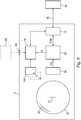
- FIG. 2 1 shows a block diagram of a position-measuring device 5 according to the invention. It comprises a graduation carrier 30 with a graduation 40, a scanner 50, a processing unit 60, and an interface unit 70.
- the graduation carrier 30 is configured annularly or as a circular disk and rotatably supported for the operation of the position measuring device 5 about a pivot point D and rotatably connected to the shaft 2, whose angular position and possibly number of revolutions covered with the position measuring device 5 to be measured.
- the measuring graduation 40 is arranged radially around the pivot point D and has at least one graduation track, the scanning of which permits position determination (angle determination).
- the scanning device 50 is arranged stationarily with respect to the graduation carrier 30 and suitably designed to scan the graduation 40 on the graduation carrier 30 and to generate position-dependent (angle-dependent) position signals PS as a function of the rotational angle of the graduation carrier 30.
- the position signals PS may include analog or digitally coded signals.
- the present invention is not limited to a physical scanning principle. Thus, known inductive, photoelectric, magnetic or capacitive sensing principles can be used.
- the position signals PS are fed to the processing unit 60 which processes them into a position value POS and outputs them to the interface unit 70.
- the processing will not be discussed here, processing steps such as signal correction, demodulation, digitization, etc. can be performed.
- position values POS it is also possible to derive further movement values such as rotational speed N (angular velocity), acceleration or jerk from the position signals PS in the processing unit 60. These may be supplied via the interface unit 70 or, as later with reference to FIGS FIGS. 5 and 6 will be shown for internal use in the position measuring device 5.
- rotational speed N angular velocity
- acceleration or jerk may be supplied via the interface unit 70 or, as later with reference to FIGS FIGS. 5 and 6 will be shown for internal use in the position measuring device 5.
- the interface unit 70 is used for communication with subsequent electronics 80 via a data transmission channel 90.
- the interface unit 70 can be designed as a serial interface, ie the data transmission via the data transmission channel 90 takes place in the form of serial data streams or data packets.
- the interface unit 70 is bidirectional, so that data D, in particular position values POS and possibly further movement values, can be sent to the sequential electronics 80 and data D, in particular parameters PAR, can be received by the sequential electronics 80.
- At least one collision sensor 100 and an evaluation unit 110 for determining collision events based on the measured values of at least one collision sensor 100 are now associated with the position-measuring device 5.
- acceleration sensors or structure-borne sound sensors ie collision sensors 100, with which accelerations can be measured, since collisions always lead to spontaneous changes, in particular a reduction, in a movement speed (negative acceleration).
- a particularly advantageous arrangement is obtained if a collision sensor 100 is provided for each spatial direction X, Y, Z, since then it is possible to deduce the impact angle of a collision from the measured values of the individual sensors.
- the collision sensor 100 can, as indicated by the dashed lines, be arranged outside the position-measuring device 5, advantageously at a point where it is mechanically rigidly coupled to the shaft 2, for example at a pivot bearing of the spindle motor 1.
- the electrical connection of the collision sensor 100 can be done in this case via a suitable connection unit 105 on the housing of the position measuring device 5 by means of a plug, screw, clamp, or a solder joint.
- the collision sensor 100 Due to the fact that collision events always have a direct effect on the position-measuring device 5 due to the mechanical coupling of the position-measuring device 5 with the shaft 2, it is considered particularly advantageous to arrange the collision sensor 100 within the housing of the position-measuring device 5. This eliminates any effort to connect the collision sensor 100 to the position measuring device 5 and also the mounting of the collision sensor 100 for coupling with the shaft 2 of the spindle motor 1 (or other suitable mechanical component of the motor spindle 10). Inside the case of the Position measuring device 5, the collision sensor 100 may be arranged, for example, together with other electronic and electromechanical components on a circuit board. It is also possible to arrange the collision sensor 100 on a mechanical component which has a mechanically particularly stiff coupling with the shaft 2, for example a rotary bearing or the coupling.
- a length measuring device position measuring device 5 'in FIG. 1
- the graduation carrier is a straight scale on which the measuring graduation is arranged.
- a scanning head is guided linearly along the scale, or the measuring graduation, wherein the scanning device 50, the processing unit 60, the interface unit 70, at least one collision sensor 100, and the evaluation unit 110 can be arranged in a housing of the scanning head.
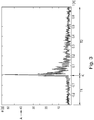
- FIG. 3 shows an example of a time course of a collision event.
- T1 the signal course before the collision
- T2 the signal course after the collision is shown.
- the collision occurs at time K and is detected by the evaluation unit 110.
- the recognition takes place via the occurrence / exceeding of one Characteristic of collision events, for example exceeding a maximum acceleration A. Since the actual time of the collision (ie the time of the first mechanical contact) and the time of detection of the collision event follow each other very shortly, these times will not be differentiated below and simplified as a collision time K denotes.
- the signal shows only statistical changes of the acceleration (signal noise).
- the collision causes a spontaneous increase in the acceleration, which exceeds the maximum acceleration A at the collision time K, so that the collision event is detected by the evaluation unit 110.
- the oscillation generated by the collision decays again until towards the end of the second period T2 the signal again shows the behavior before the collision.
- FIG. 4 shows a first embodiment of an evaluation unit 110. It is suitable for processing and evaluating the measured values of analog collision sensors 100.
- the analog measured values MA of the collision sensor 100 are fed to an A / D converter 120, which digitizes the analog measured values MA.
- the resulting digital measured values M are supplied to a memory unit 140 and to a control unit 150.
- the control unit 150 controls the essential processes in the evaluation unit 110. Thus, it supplies to the A / D converter 120 a sampling clock signal TA which determines the sampling rate with which the analog measurement values MA are digitized. It also controls the storage of the digital measurements M in the memory unit 140. In addition, it is designed to detect collision events.
- the analog measured values MA of the collision sensor 100 are continuously digitized in the time grid of the sampling clock signal TA and stored in the memory unit 140 in succession. This results in the storage unit 140, a digital image of the waveform, which is output from the collision sensor 100.
- the storage takes place in a RAM memory area 142 of the memory unit 140.
- the memory capacity is selected such that at least the signal profile of a collision event can be stored.
- the RAM memory area 142 is operated as a ring memory, which means that when the last memory cell of the RAM memory area 142 provided for the signal course of a collision event is jumped back to the first memory cell, the respectively oldest measured values are overwritten.
- the ongoing operation can be started with the switching on of the machine (and thus the switching on of the position measuring device 5, or 5 ').
- the starting or stopping of the current operation via commands that are sent from the subsequent electronics 80 to the position measuring device 5, and 5 '.
- the control unit 150 evaluates the incoming digital measured values M with respect to at least one characteristic of a collision event and controls the storing of the digital measured values M in the memory unit 140 as a function of this.
- the evaluation likewise takes place in the time grid of the sampling clock signal TA.
- the incoming measured values M are checked with regard to exceeding a limit value.
- the frequency of the sampling clock signal TA is chosen so that collision events can be reliably detected.
- machine parameters such as e.g. maximum speeds, or accelerations in normal operation, as well as weight and weight distribution of the machine components affected by possible collisions.
- control unit 150 can also use the analog measured values MA of the collision sensor 100 for evaluation with respect to a Be fed collision event.
- the check for exceeding the limit value can in this case be done by comparing the analog measured values MA with the limit value by means of a comparator.
- a plurality of limit values can be provided so that different severity collision events can be distinguished.
- control unit 150 determines a collision event at collision time K, it continues to store the digital measured values M over the second period T2 and then stops the recording.
- the RAM memory area 142 provided for the signal course of the collision event is dimensioned such that it comprises the first time period T1 before the collision and the second time period T2 after the collision.
- control unit 150 generates an error message ERR for signaling the detected collision event via the interface unit 70 and the data transmission channel 90 to the sequential electronics 80.
- the transmission of the ERR error message can take the form of at least one status bit contained in a data frame included in the current operation for the transmission of position values POS is used. But it can also be a separate line provided for this purpose.
- the sequential electronics 80 can respond immediately to a collision event that has occurred, but postpone the analysis of the event to a later date.
- the memory unit 140 can also be supplied with the position values POS and there stored parallel to the digital measured values M. In this way, a correlation between the course of the measured values M and the position values POS can be determined in the subsequent electronics 80.
- the RAM memory area 142 is designed as a volatile memory that loses the memory content without a power supply, then it is advantageous to provide a non-volatile, programmable memory area 144 (EEPROM, flash memory) in which signal waveforms stored in the RAM memory area 142 after completion of the Record is storable. Since a collision often leads to an emergency shutdown in a machine tool, the recorded data is retained for later evaluation.
- EEPROM electrically erasable programmable memory area 144
- the storage capacity of the RAM memory area 142 and / or the programmable memory area 144 of the memory unit 144 is advantageously dimensioned such that a plurality of signal sequences of collision events can be stored.
- collision events are not clear, in particular in the case of machine tools, ie they can also have other causes than collisions.
- accelerations of the same order of magnitude as occur in collisions can occur.
- One possible cause of such high accelerations are so-called "chatter vibrations". They arise, for example, when milling workpieces by the forces that occur when the cutting edges of the milling cutter hit the workpiece and do not necessarily constitute a malfunction during machining.
- Chatter vibrations arise, for example, when milling workpieces by the forces that occur when the cutting edges of the milling cutter hit the workpiece and do not necessarily constitute a malfunction during machining.
- Chatter vibrations due to the rotation of the cutter and the regular arrangement of cutting over the circumference of the milling cutter, an oscillating course, the oscillation usually spills over several periods.
- Another cause for the occurrence of high accelerations may be device resonances of the machine tool. Again, these are oscillating, periodic waveforms.
- the evaluation unit 110 may be suitably configured such that such events (periodic exceeding of acceleration limit values) are recognizable and in such cases the storage of measured values is continued. This increases the likelihood that a collision event detected due to a characteristic characteristic being exceeded will be the result of an actual collision.
- the final confirmation that a collision was present also takes place here by evaluation of the recorded signal curve in the subsequent electronics 80.
- the setting of the parameters PAR is advantageously carried out by the subsequent electronics 80 via the data transmission channel 90 and the interface unit 70.
- the components of the evaluation unit 110 may also be present multiple times, so that the digital measured values M of the individual sensors can be processed and stored substantially in parallel.
- the parameters PAR per collision sensor can be provided.
- FIG. 5 shows an alternative embodiment of an evaluation unit 210. It is also suitable for the use of analog collision sensors 100. Components already in conjunction with FIG. 4 have been described, carry the same reference numerals.
- the evaluation unit 210 comprises a filter unit 130, which is arranged between the A / D converter 120 and the control unit 150, or the memory unit 140.
- the filter unit 130 is designed as a band rejection filter, in particular as a notch filter, so that the frequency components of at least one frequency band of the frequency spectrum of the measured values are damped or suppressed. In this way, events that cause a periodic exceeding of acceleration limits (chatter vibrations, device resonances) can be filtered out. Since the pulse-shaped course of the measured values of the collision sensor, as shown in FIG FIG. 3 Despite the filtering in the control unit 150, a check for collision events based on the detection of an exceeding of the above-mentioned acceleration limit values can continue to take place. On the other hand, if necessary, it can be dispensed with, the control unit 150 form so that they Recognizes oscillating acceleration events, since they are already filtered out by the filter unit 130.
- the frequency band to be filtered is adjustable. This can be done via suitable parameters PAR, which can be supplied to the filter unit 130 by the control unit 150.
- the frequency band to be filtered is set at least one frequency band to be filtered automatically as a function of this relationship. This is the case, for example, with position measuring devices 5, which measure the angular position of the shaft 2 of the motor spindle 10 of a machine tool.
- the frequency of chatter vibrations results from the rotational speed N of the spindle motor 1 and the number of cutting edges of the tool 4 used. If chatter vibrations are to be filtered, the frequency band to be filtered is determined by multiplying the rotational speed N by a multiplier. This can be supplied to the filter unit 130 by the control unit 150.
- filter unit 130 in FIG. 5 it is a digital filter.
- an analog filter unit may be arranged in front of the A / D converter 120.
- FIG. 6 shows a further embodiment of an evaluation unit 310. It is suitable for the use of digital collision sensors 100. Components, already in conjunction with the FIGS. 4 or 5 have been described, carry the same reference numerals.
- a digital sensor interface 160 is provided in this embodiment in order to directly detect the digital measured values M of a collision sensor 100.
- the sensor interface 160 is preferably a serial interface, for example an I2C interface. If a plurality of collision sensors 100 are present, they can either be operated in a bus mode at only one sensor interface 160, but a sensor interface 160 can also be provided for each collision sensor 100.
- the request of digital measured values M of the collision sensor 100 via the sensor interface 160 is also initiated in this example with advantage in the time grid of the sampling clock signal TA of the control unit 150.
- Incoming digital measured values M are, as in the preceding example, first supplied to the filter unit 130 before they are evaluated in the control unit 150 or stored in the memory unit 140.
- this embodiment can be performed without filter unit 130.
- the detection of oscillating acceleration events resulting from chatter vibrations or device resonances can be done in the sequential electronics 80 or in the control unit 150.
- sensors can be used in addition to, or at the location of, acceleration sensors or structure-borne sound sensors with which collision events can be detected, for example sensors with which a bending or displacement of a machine part as a result of a collision can be detected.
Landscapes
- Physics & Mathematics (AREA)
- General Physics & Mathematics (AREA)
- Engineering & Computer Science (AREA)
- Human Computer Interaction (AREA)
- Manufacturing & Machinery (AREA)
- Automation & Control Theory (AREA)
- Mechanical Engineering (AREA)
- Signal Processing (AREA)
- Numerical Control (AREA)
- Transmission And Conversion Of Sensor Element Output (AREA)
- Arrangements For Transmission Of Measured Signals (AREA)
Applications Claiming Priority (1)
| Application Number | Priority Date | Filing Date | Title |
|---|---|---|---|
| DE102018209136.6A DE102018209136A1 (de) | 2018-06-08 | 2018-06-08 | Positionsmesseinrichtung und Verfahren zum Betreiben einer Positionsmesseinrichtung |
Publications (2)
| Publication Number | Publication Date |
|---|---|
| EP3578295A1 true EP3578295A1 (fr) | 2019-12-11 |
| EP3578295B1 EP3578295B1 (fr) | 2021-03-17 |
Family
ID=65818426
Family Applications (1)
| Application Number | Title | Priority Date | Filing Date |
|---|---|---|---|
| EP19163617.4A Active EP3578295B1 (fr) | 2018-06-08 | 2019-03-19 | Dispositif de mesure de position et procédé de fonctionnement d'un dispositif de mesure de position |
Country Status (6)
| Country | Link |
|---|---|
| US (1) | US11280640B2 (fr) |
| EP (1) | EP3578295B1 (fr) |
| JP (1) | JP7384577B2 (fr) |
| CN (1) | CN110579192B (fr) |
| DE (1) | DE102018209136A1 (fr) |
| ES (1) | ES2858598T3 (fr) |
Cited By (1)
| Publication number | Priority date | Publication date | Assignee | Title |
|---|---|---|---|---|
| EP4129565A4 (fr) * | 2020-09-02 | 2024-04-24 | DMG Mori Co., Ltd. | Machine-outil et dispositif de traitement d'informations |
Families Citing this family (3)
| Publication number | Priority date | Publication date | Assignee | Title |
|---|---|---|---|---|
| DE102020201282A1 (de) * | 2020-02-03 | 2021-08-05 | Dr. Johannes Heidenhain Gesellschaft Mit Beschränkter Haftung | Positionsmesseinrichtung und Verfahren zu deren Betrieb |
| CN111604901B (zh) * | 2020-05-18 | 2022-06-24 | 哈尔滨工业大学 | 一种适用于机械手在手操作的目标旋转检测方法 |
| DE102020211550A1 (de) * | 2020-09-15 | 2022-03-17 | Kesseböhmer Holding Kg | Antriebssystem zum Bewegen einer höhenverstellbaren Tischplatte, Tisch mit einem solchen Antriebssystem und Verfahren zum Erfassen einer Kollision einer höhenverstellbaren Tischplatte |
Citations (3)
| Publication number | Priority date | Publication date | Assignee | Title |
|---|---|---|---|---|
| WO2003023528A2 (fr) | 2001-09-12 | 2003-03-20 | Werner Kluft | Systeme de surveillance, ainsi que procede de surveillance, parallele aux processus, de situations de collision ou de surcharge sur des machines-outils |
| US20050238043A1 (en) * | 2004-04-27 | 2005-10-27 | Charmilles Technologies S.A. | Numerically controlled drive device with device for detecting operating anomalies intended for detecting accidental collisions and method of detecting operating anomalies for this device |
| US20150352679A1 (en) * | 2013-03-07 | 2015-12-10 | Mitsubishi Heavy Industries, Ltd. | Abnormality diagnosis device for machine tool, and abnormality diagnosis method |
Family Cites Families (14)
| Publication number | Priority date | Publication date | Assignee | Title |
|---|---|---|---|---|
| DE2207831A1 (de) * | 1972-02-19 | 1973-08-23 | Dynamit Nobel Ag | Elektronischer sensor zum ausloesen von sicherheitseinrichtungen beim aufprall von fahrzeugen |
| DE2937431C2 (de) * | 1979-09-15 | 1987-02-05 | Ernst Leitz Wetzlar Gmbh, 6330 Wetzlar | Einrichtung zur Meßwerterfassung an Prüflingen |
| GB8431746D0 (en) * | 1984-12-17 | 1985-01-30 | Renishaw Plc | Contact-sensing probe |
| DE10054062A1 (de) * | 2000-10-31 | 2002-05-16 | Heidenhain Gmbh Dr Johannes | Verfahren zur Positionsbestimmung und Positionsmesseinrichtung zur Ausführung des Verfahrens |
| DE10125533B4 (de) * | 2001-05-23 | 2005-06-02 | Dr. Johannes Heidenhain Gmbh | Verfahren zum Betrieb einer Positionsmesseinrichtung sowie Positionsmesseinrichtung und Auswerteeinheit zur Durchführung des Verfahrens |
| DE102007057376A1 (de) * | 2007-11-26 | 2009-05-28 | Baumer Hübner GmbH | Drehgeber mit interner Fehlerkontrolle und Verfahren hierzu |
| DE102010018250A1 (de) * | 2010-04-23 | 2011-10-27 | Carl Zeiss Industrielle Messtechnik Gmbh | Verfahren zur Koordinatenmessung an Werkstücken auf einem Koordinatenmessgerät |
| DE102011003374A1 (de) * | 2011-01-31 | 2012-08-02 | Deckel Maho Pfronten Gmbh | Werkzeugmaschine mit einer Vorrichtung zur Kollisionsüberwachung |
| DE102012103911A1 (de) * | 2012-05-04 | 2013-11-07 | Carl Mahr Holding Gmbh | Messvorrichtung für dimensionelle Mess- und Kenngrößen mit separater Steuereinrichtung |
| EP2889573B1 (fr) * | 2013-12-24 | 2016-06-15 | Tesa Sa | Tête de mesure inclinable motorisée |
| DE102014225867A1 (de) * | 2014-12-15 | 2016-06-16 | Dr. Johannes Heidenhain Gmbh | Vorrichtung und Verfahren zur Überprüfung eines Arbeitstaktsignals einer Positionsmesseinrichtung |
| JP6227603B2 (ja) * | 2015-09-10 | 2017-11-08 | ファナック株式会社 | 衝撃検出機能を有する電子機器 |
| DE102015223061A1 (de) * | 2015-11-23 | 2017-05-24 | Dr. Johannes Heidenhain Gesellschaft Mit Beschränkter Haftung | Winkelmesseinrichtung und Verfahren zum Betreiben einer Winkelmesseinrichtung |
| DE102016214456A1 (de) * | 2016-08-04 | 2018-02-08 | Dr. Johannes Heidenhain Gesellschaft Mit Beschränkter Haftung | Positionsmesseinrichtung und Verfahren zum Betreiben einer Positionsmesseinrichtung |
-
2018
- 2018-06-08 DE DE102018209136.6A patent/DE102018209136A1/de not_active Withdrawn
-
2019
- 2019-03-19 EP EP19163617.4A patent/EP3578295B1/fr active Active
- 2019-03-19 ES ES19163617T patent/ES2858598T3/es active Active
- 2019-06-04 CN CN201910481936.3A patent/CN110579192B/zh active Active
- 2019-06-07 US US16/434,187 patent/US11280640B2/en active Active
- 2019-06-07 JP JP2019106954A patent/JP7384577B2/ja active Active
Patent Citations (3)
| Publication number | Priority date | Publication date | Assignee | Title |
|---|---|---|---|---|
| WO2003023528A2 (fr) | 2001-09-12 | 2003-03-20 | Werner Kluft | Systeme de surveillance, ainsi que procede de surveillance, parallele aux processus, de situations de collision ou de surcharge sur des machines-outils |
| US20050238043A1 (en) * | 2004-04-27 | 2005-10-27 | Charmilles Technologies S.A. | Numerically controlled drive device with device for detecting operating anomalies intended for detecting accidental collisions and method of detecting operating anomalies for this device |
| US20150352679A1 (en) * | 2013-03-07 | 2015-12-10 | Mitsubishi Heavy Industries, Ltd. | Abnormality diagnosis device for machine tool, and abnormality diagnosis method |
Cited By (1)
| Publication number | Priority date | Publication date | Assignee | Title |
|---|---|---|---|---|
| EP4129565A4 (fr) * | 2020-09-02 | 2024-04-24 | DMG Mori Co., Ltd. | Machine-outil et dispositif de traitement d'informations |
Also Published As
| Publication number | Publication date |
|---|---|
| JP7384577B2 (ja) | 2023-11-21 |
| US20190376816A1 (en) | 2019-12-12 |
| DE102018209136A1 (de) | 2019-12-12 |
| EP3578295B1 (fr) | 2021-03-17 |
| JP2019215340A (ja) | 2019-12-19 |
| CN110579192A (zh) | 2019-12-17 |
| ES2858598T3 (es) | 2021-09-30 |
| CN110579192B (zh) | 2023-04-07 |
| US11280640B2 (en) | 2022-03-22 |
Similar Documents
| Publication | Publication Date | Title |
|---|---|---|
| EP3578295B1 (fr) | Dispositif de mesure de position et procédé de fonctionnement d'un dispositif de mesure de position | |
| EP3460410B1 (fr) | Dispositif de mesure de position et procédé de fonctionnement d'un dispositif de mesure de position | |
| DE69935177T2 (de) | Industrielle Maschine mit Einrichtung zur Feststellung einer unregelmässigen Schwingung | |
| EP1425640B1 (fr) | Systeme et procede servant a surveiller des composants de machines-outils, lors du deroulement de processus | |
| DE112013006990B4 (de) | Encoder und Servomotor | |
| DE102019001972A1 (de) | Störungserfassungsvorrichtung | |
| EP1425635B1 (fr) | Systeme de surveillance, ainsi que procede de surveillance, parallele aux processus, de situations de collision ou de surcharge sur des machines-outils | |
| EP1987316B1 (fr) | Surveillance fiable de la vitesse d'appareils de mesure de coordonnees | |
| WO2006103249A2 (fr) | Procede et dispositif de commande pour la reaction ciblee en cas de contact entre un element d'une machine et un objet | |
| EP4252962B1 (fr) | Dispositif et procédé de détection de l'approche d'un outil sur une pièce | |
| EP2023092B1 (fr) | Appareil de mesure de position et procédé de transmission d'une information de mouvement | |
| EP3171135B1 (fr) | Clinomètre et procédé de fonctionnement d'un clinomètre | |
| EP4137269B1 (fr) | Dispositif et procédé de détection d'un contact entre un outil et une pièce | |
| EP3964903B1 (fr) | Dispositif et procédé de traitement des valeurs mesurées dépendant de la rotation | |
| EP2505965B1 (fr) | Procédé et unité de surveillance destinés à la vérification de valeurs de position | |
| WO2008025577A1 (fr) | Procédé et dispositif destinés à surveiller les collisions d'un élément de machine avec un objet dans une machine-outil et/ou dans une machine de production et/ou dans une machine qui se présente sous le forme d'un robot | |
| EP3035000B1 (fr) | Dispositif et procede de verification d'un signal de travail d'un dispositif de mesure de position | |
| EP1888299A1 (fr) | Procede et dispositif de detection de rupture d'outil en cours de processus et machine-outil associee | |
| EP1614990B2 (fr) | Capteur de position et méthode pour mésurer la position | |
| DE102016004569B4 (de) | Numerische Steuervorrichtung mit Koordinatenwerterfassungsfunktion, die weder ein Skip-Signal noch eine Tastenbetätigung benötigt | |
| WO2017093126A1 (fr) | Unité de commande et procédé pour commander une machine-outil, et utilisation | |
| EP3760979B1 (fr) | Dispositif de mesure de position et procédé de fonctionnement d'un dispositif de mesure de position | |
| DE102019128041A1 (de) | Analysegerät, Analyseverfahren und Bearbeitungssystem | |
| DE202006019339U1 (de) | Messeinrichtung für eine Werkzeugmaschine zum Überwachen einer Unwucht | |
| DD301875A9 (de) | Verfahren und Vorrichtung zur Ermittlung der radialen und tangentialen Bezugslage von Werkzeug und Werkstueck durch Signalisierung einer ersten Beruehrung bei Werkzeugmaschinen |
Legal Events
| Date | Code | Title | Description |
|---|---|---|---|
| PUAI | Public reference made under article 153(3) epc to a published international application that has entered the european phase |
Free format text: ORIGINAL CODE: 0009012 |
|
| STAA | Information on the status of an ep patent application or granted ep patent |
Free format text: STATUS: THE APPLICATION HAS BEEN PUBLISHED |
|
| AK | Designated contracting states |
Kind code of ref document: A1 Designated state(s): AL AT BE BG CH CY CZ DE DK EE ES FI FR GB GR HR HU IE IS IT LI LT LU LV MC MK MT NL NO PL PT RO RS SE SI SK SM TR |
|
| AX | Request for extension of the european patent |
Extension state: BA ME |
|
| STAA | Information on the status of an ep patent application or granted ep patent |
Free format text: STATUS: REQUEST FOR EXAMINATION WAS MADE |
|
| 17P | Request for examination filed |
Effective date: 20200612 |
|
| RBV | Designated contracting states (corrected) |
Designated state(s): AL AT BE BG CH CY CZ DE DK EE ES FI FR GB GR HR HU IE IS IT LI LT LU LV MC MK MT NL NO PL PT RO RS SE SI SK SM TR |
|
| GRAP | Despatch of communication of intention to grant a patent |
Free format text: ORIGINAL CODE: EPIDOSNIGR1 |
|
| STAA | Information on the status of an ep patent application or granted ep patent |
Free format text: STATUS: GRANT OF PATENT IS INTENDED |
|
| INTG | Intention to grant announced |
Effective date: 20201014 |
|
| GRAS | Grant fee paid |
Free format text: ORIGINAL CODE: EPIDOSNIGR3 |
|
| GRAA | (expected) grant |
Free format text: ORIGINAL CODE: 0009210 |
|
| STAA | Information on the status of an ep patent application or granted ep patent |
Free format text: STATUS: THE PATENT HAS BEEN GRANTED |
|
| AK | Designated contracting states |
Kind code of ref document: B1 Designated state(s): AL AT BE BG CH CY CZ DE DK EE ES FI FR GB GR HR HU IE IS IT LI LT LU LV MC MK MT NL NO PL PT RO RS SE SI SK SM TR |
|
| REG | Reference to a national code |
Ref country code: GB Ref legal event code: FG4D Free format text: NOT ENGLISH |
|
| REG | Reference to a national code |
Ref country code: CH Ref legal event code: EP Ref country code: CH Ref legal event code: NV Representative=s name: ICB INGENIEURS CONSEILS EN BREVETS SA, CH |
|
| REG | Reference to a national code |
Ref country code: DE Ref legal event code: R096 Ref document number: 502019000983 Country of ref document: DE |
|
| REG | Reference to a national code |
Ref country code: IE Ref legal event code: FG4D Free format text: LANGUAGE OF EP DOCUMENT: GERMAN |
|
| REG | Reference to a national code |
Ref country code: AT Ref legal event code: REF Ref document number: 1371795 Country of ref document: AT Kind code of ref document: T Effective date: 20210415 |
|
| REG | Reference to a national code |
Ref country code: LT Ref legal event code: MG9D |
|
| PG25 | Lapsed in a contracting state [announced via postgrant information from national office to epo] |
Ref country code: HR Free format text: LAPSE BECAUSE OF FAILURE TO SUBMIT A TRANSLATION OF THE DESCRIPTION OR TO PAY THE FEE WITHIN THE PRESCRIBED TIME-LIMIT Effective date: 20210317 Ref country code: GR Free format text: LAPSE BECAUSE OF FAILURE TO SUBMIT A TRANSLATION OF THE DESCRIPTION OR TO PAY THE FEE WITHIN THE PRESCRIBED TIME-LIMIT Effective date: 20210618 Ref country code: FI Free format text: LAPSE BECAUSE OF FAILURE TO SUBMIT A TRANSLATION OF THE DESCRIPTION OR TO PAY THE FEE WITHIN THE PRESCRIBED TIME-LIMIT Effective date: 20210317 Ref country code: BG Free format text: LAPSE BECAUSE OF FAILURE TO SUBMIT A TRANSLATION OF THE DESCRIPTION OR TO PAY THE FEE WITHIN THE PRESCRIBED TIME-LIMIT Effective date: 20210617 Ref country code: NO Free format text: LAPSE BECAUSE OF FAILURE TO SUBMIT A TRANSLATION OF THE DESCRIPTION OR TO PAY THE FEE WITHIN THE PRESCRIBED TIME-LIMIT Effective date: 20210617 |
|
| REG | Reference to a national code |
Ref country code: NL Ref legal event code: MP Effective date: 20210317 |
|
| PG25 | Lapsed in a contracting state [announced via postgrant information from national office to epo] |
Ref country code: SE Free format text: LAPSE BECAUSE OF FAILURE TO SUBMIT A TRANSLATION OF THE DESCRIPTION OR TO PAY THE FEE WITHIN THE PRESCRIBED TIME-LIMIT Effective date: 20210317 Ref country code: LV Free format text: LAPSE BECAUSE OF FAILURE TO SUBMIT A TRANSLATION OF THE DESCRIPTION OR TO PAY THE FEE WITHIN THE PRESCRIBED TIME-LIMIT Effective date: 20210317 Ref country code: RS Free format text: LAPSE BECAUSE OF FAILURE TO SUBMIT A TRANSLATION OF THE DESCRIPTION OR TO PAY THE FEE WITHIN THE PRESCRIBED TIME-LIMIT Effective date: 20210317 |
|
| PG25 | Lapsed in a contracting state [announced via postgrant information from national office to epo] |
Ref country code: NL Free format text: LAPSE BECAUSE OF FAILURE TO SUBMIT A TRANSLATION OF THE DESCRIPTION OR TO PAY THE FEE WITHIN THE PRESCRIBED TIME-LIMIT Effective date: 20210317 |
|
| REG | Reference to a national code |
Ref country code: ES Ref legal event code: FG2A Ref document number: 2858598 Country of ref document: ES Kind code of ref document: T3 Effective date: 20210930 |
|
| PG25 | Lapsed in a contracting state [announced via postgrant information from national office to epo] |
Ref country code: SM Free format text: LAPSE BECAUSE OF FAILURE TO SUBMIT A TRANSLATION OF THE DESCRIPTION OR TO PAY THE FEE WITHIN THE PRESCRIBED TIME-LIMIT Effective date: 20210317 Ref country code: LT Free format text: LAPSE BECAUSE OF FAILURE TO SUBMIT A TRANSLATION OF THE DESCRIPTION OR TO PAY THE FEE WITHIN THE PRESCRIBED TIME-LIMIT Effective date: 20210317 Ref country code: EE Free format text: LAPSE BECAUSE OF FAILURE TO SUBMIT A TRANSLATION OF THE DESCRIPTION OR TO PAY THE FEE WITHIN THE PRESCRIBED TIME-LIMIT Effective date: 20210317 |
|
| PG25 | Lapsed in a contracting state [announced via postgrant information from national office to epo] |
Ref country code: IS Free format text: LAPSE BECAUSE OF FAILURE TO SUBMIT A TRANSLATION OF THE DESCRIPTION OR TO PAY THE FEE WITHIN THE PRESCRIBED TIME-LIMIT Effective date: 20210717 Ref country code: PL Free format text: LAPSE BECAUSE OF FAILURE TO SUBMIT A TRANSLATION OF THE DESCRIPTION OR TO PAY THE FEE WITHIN THE PRESCRIBED TIME-LIMIT Effective date: 20210317 Ref country code: PT Free format text: LAPSE BECAUSE OF FAILURE TO SUBMIT A TRANSLATION OF THE DESCRIPTION OR TO PAY THE FEE WITHIN THE PRESCRIBED TIME-LIMIT Effective date: 20210719 Ref country code: RO Free format text: LAPSE BECAUSE OF FAILURE TO SUBMIT A TRANSLATION OF THE DESCRIPTION OR TO PAY THE FEE WITHIN THE PRESCRIBED TIME-LIMIT Effective date: 20210317 Ref country code: SK Free format text: LAPSE BECAUSE OF FAILURE TO SUBMIT A TRANSLATION OF THE DESCRIPTION OR TO PAY THE FEE WITHIN THE PRESCRIBED TIME-LIMIT Effective date: 20210317 |
|
| REG | Reference to a national code |
Ref country code: BE Ref legal event code: MM Effective date: 20210331 |
|
| REG | Reference to a national code |
Ref country code: DE Ref legal event code: R097 Ref document number: 502019000983 Country of ref document: DE |
|
| PLBE | No opposition filed within time limit |
Free format text: ORIGINAL CODE: 0009261 |
|
| STAA | Information on the status of an ep patent application or granted ep patent |
Free format text: STATUS: NO OPPOSITION FILED WITHIN TIME LIMIT |
|
| PG25 | Lapsed in a contracting state [announced via postgrant information from national office to epo] |
Ref country code: LU Free format text: LAPSE BECAUSE OF NON-PAYMENT OF DUE FEES Effective date: 20210319 Ref country code: IE Free format text: LAPSE BECAUSE OF NON-PAYMENT OF DUE FEES Effective date: 20210319 Ref country code: DK Free format text: LAPSE BECAUSE OF FAILURE TO SUBMIT A TRANSLATION OF THE DESCRIPTION OR TO PAY THE FEE WITHIN THE PRESCRIBED TIME-LIMIT Effective date: 20210317 Ref country code: AL Free format text: LAPSE BECAUSE OF FAILURE TO SUBMIT A TRANSLATION OF THE DESCRIPTION OR TO PAY THE FEE WITHIN THE PRESCRIBED TIME-LIMIT Effective date: 20210317 Ref country code: MC Free format text: LAPSE BECAUSE OF FAILURE TO SUBMIT A TRANSLATION OF THE DESCRIPTION OR TO PAY THE FEE WITHIN THE PRESCRIBED TIME-LIMIT Effective date: 20210317 |
|
| 26N | No opposition filed |
Effective date: 20211220 |
|
| PG25 | Lapsed in a contracting state [announced via postgrant information from national office to epo] |
Ref country code: SI Free format text: LAPSE BECAUSE OF FAILURE TO SUBMIT A TRANSLATION OF THE DESCRIPTION OR TO PAY THE FEE WITHIN THE PRESCRIBED TIME-LIMIT Effective date: 20210317 |
|
| PG25 | Lapsed in a contracting state [announced via postgrant information from national office to epo] |
Ref country code: IS Free format text: LAPSE BECAUSE OF FAILURE TO SUBMIT A TRANSLATION OF THE DESCRIPTION OR TO PAY THE FEE WITHIN THE PRESCRIBED TIME-LIMIT Effective date: 20210717 Ref country code: FR Free format text: LAPSE BECAUSE OF NON-PAYMENT OF DUE FEES Effective date: 20210517 |
|
| PG25 | Lapsed in a contracting state [announced via postgrant information from national office to epo] |
Ref country code: BE Free format text: LAPSE BECAUSE OF NON-PAYMENT OF DUE FEES Effective date: 20210331 |
|
| PG25 | Lapsed in a contracting state [announced via postgrant information from national office to epo] |
Ref country code: CY Free format text: LAPSE BECAUSE OF FAILURE TO SUBMIT A TRANSLATION OF THE DESCRIPTION OR TO PAY THE FEE WITHIN THE PRESCRIBED TIME-LIMIT Effective date: 20210317 |
|
| PG25 | Lapsed in a contracting state [announced via postgrant information from national office to epo] |
Ref country code: HU Free format text: LAPSE BECAUSE OF FAILURE TO SUBMIT A TRANSLATION OF THE DESCRIPTION OR TO PAY THE FEE WITHIN THE PRESCRIBED TIME-LIMIT; INVALID AB INITIO Effective date: 20190319 |
|
| PG25 | Lapsed in a contracting state [announced via postgrant information from national office to epo] |
Ref country code: MK Free format text: LAPSE BECAUSE OF FAILURE TO SUBMIT A TRANSLATION OF THE DESCRIPTION OR TO PAY THE FEE WITHIN THE PRESCRIBED TIME-LIMIT Effective date: 20210317 |
|
| PG25 | Lapsed in a contracting state [announced via postgrant information from national office to epo] |
Ref country code: TR Free format text: LAPSE BECAUSE OF FAILURE TO SUBMIT A TRANSLATION OF THE DESCRIPTION OR TO PAY THE FEE WITHIN THE PRESCRIBED TIME-LIMIT Effective date: 20210317 |
|
| PG25 | Lapsed in a contracting state [announced via postgrant information from national office to epo] |
Ref country code: MT Free format text: LAPSE BECAUSE OF FAILURE TO SUBMIT A TRANSLATION OF THE DESCRIPTION OR TO PAY THE FEE WITHIN THE PRESCRIBED TIME-LIMIT Effective date: 20210317 |
|
| REG | Reference to a national code |
Ref country code: AT Ref legal event code: MM01 Ref document number: 1371795 Country of ref document: AT Kind code of ref document: T Effective date: 20240319 |
|
| PGFP | Annual fee paid to national office [announced via postgrant information from national office to epo] |
Ref country code: ES Payment date: 20250429 Year of fee payment: 7 |
|
| PGFP | Annual fee paid to national office [announced via postgrant information from national office to epo] |
Ref country code: CH Payment date: 20250401 Year of fee payment: 7 |
|
| PG25 | Lapsed in a contracting state [announced via postgrant information from national office to epo] |
Ref country code: AT Free format text: LAPSE BECAUSE OF NON-PAYMENT OF DUE FEES Effective date: 20240319 |
|
| REG | Reference to a national code |
Ref country code: CH Ref legal event code: R17 Free format text: ST27 STATUS EVENT CODE: U-0-0-R10-R17 (AS PROVIDED BY THE NATIONAL OFFICE) Effective date: 20260108 |
|
| REG | Reference to a national code |
Ref country code: CH Ref legal event code: U11 Free format text: ST27 STATUS EVENT CODE: U-0-0-U10-U11 (AS PROVIDED BY THE NATIONAL OFFICE) Effective date: 20260401 |
|
| PGFP | Annual fee paid to national office [announced via postgrant information from national office to epo] |
Ref country code: GB Payment date: 20260324 Year of fee payment: 8 |
|
| PGFP | Annual fee paid to national office [announced via postgrant information from national office to epo] |
Ref country code: DE Payment date: 20260319 Year of fee payment: 8 |
|
| PGFP | Annual fee paid to national office [announced via postgrant information from national office to epo] |
Ref country code: AT Payment date: 20260410 Year of fee payment: 5 |
|
| PGFP | Annual fee paid to national office [announced via postgrant information from national office to epo] |
Ref country code: IT Payment date: 20260324 Year of fee payment: 8 |
|
| PGFP | Annual fee paid to national office [announced via postgrant information from national office to epo] |
Ref country code: CZ Payment date: 20260317 Year of fee payment: 8 |