EP2023227A1 - Schaltung und verfahren zur überwachung des punkts maximaler leistung für solarenergiequellen und solargenerator mit der schaltung - Google Patents
Schaltung und verfahren zur überwachung des punkts maximaler leistung für solarenergiequellen und solargenerator mit der schaltung Download PDFInfo
- Publication number
- EP2023227A1 EP2023227A1 EP07730424A EP07730424A EP2023227A1 EP 2023227 A1 EP2023227 A1 EP 2023227A1 EP 07730424 A EP07730424 A EP 07730424A EP 07730424 A EP07730424 A EP 07730424A EP 2023227 A1 EP2023227 A1 EP 2023227A1
- Authority
- EP
- European Patent Office
- Prior art keywords
- pmp
- current
- point
- voltage
- value
- Prior art date
- Legal status (The legal status is an assumption and is not a legal conclusion. Google has not performed a legal analysis and makes no representation as to the accuracy of the status listed.)
- Withdrawn
Links
- 238000000034 method Methods 0.000 title claims abstract description 48
- 238000012544 monitoring process Methods 0.000 title abstract 2
- 238000005259 measurement Methods 0.000 claims abstract description 36
- 238000004364 calculation method Methods 0.000 claims description 37
- 230000003750 conditioning effect Effects 0.000 claims description 33
- 230000006870 function Effects 0.000 claims description 21
- 230000014509 gene expression Effects 0.000 claims description 11
- 239000000463 material Substances 0.000 claims description 5
- 230000001419 dependent effect Effects 0.000 claims description 4
- 238000003860 storage Methods 0.000 claims description 4
- 238000004422 calculation algorithm Methods 0.000 abstract description 9
- 230000005611 electricity Effects 0.000 abstract description 3
- NTOPKICPEQUPPH-UHFFFAOYSA-N IPMP Natural products COC1=NC=CN=C1C(C)C NTOPKICPEQUPPH-UHFFFAOYSA-N 0.000 abstract 1
- 230000001276 controlling effect Effects 0.000 description 6
- 238000010586 diagram Methods 0.000 description 6
- 230000008859 change Effects 0.000 description 5
- 238000002940 Newton-Raphson method Methods 0.000 description 3
- 230000008901 benefit Effects 0.000 description 3
- 230000000694 effects Effects 0.000 description 3
- 238000004519 manufacturing process Methods 0.000 description 3
- 230000001105 regulatory effect Effects 0.000 description 3
- 239000000523 sample Substances 0.000 description 3
- 235000020004 porter Nutrition 0.000 description 2
- 230000008569 process Effects 0.000 description 2
- 230000005855 radiation Effects 0.000 description 2
- 239000002028 Biomass Substances 0.000 description 1
- 101100190845 Neurospora crassa (strain ATCC 24698 / 74-OR23-1A / CBS 708.71 / DSM 1257 / FGSC 987) pmp-1 gene Proteins 0.000 description 1
- 230000032683 aging Effects 0.000 description 1
- 238000004458 analytical method Methods 0.000 description 1
- 238000002485 combustion reaction Methods 0.000 description 1
- 230000000295 complement effect Effects 0.000 description 1
- 230000003247 decreasing effect Effects 0.000 description 1
- 238000009826 distribution Methods 0.000 description 1
- 230000007613 environmental effect Effects 0.000 description 1
- 238000000605 extraction Methods 0.000 description 1
- 239000012530 fluid Substances 0.000 description 1
- 239000002803 fossil fuel Substances 0.000 description 1
- 238000011430 maximum method Methods 0.000 description 1
- 230000007246 mechanism Effects 0.000 description 1
- 230000010355 oscillation Effects 0.000 description 1
- 230000000737 periodic effect Effects 0.000 description 1
- 230000009467 reduction Effects 0.000 description 1
- 230000010512 thermal transition Effects 0.000 description 1
- 230000009466 transformation Effects 0.000 description 1
- XLYOFNOQVPJJNP-UHFFFAOYSA-N water Substances O XLYOFNOQVPJJNP-UHFFFAOYSA-N 0.000 description 1
Images




Classifications
-
- G—PHYSICS
- G05—CONTROLLING; REGULATING
- G05F—SYSTEMS FOR REGULATING ELECTRIC OR MAGNETIC VARIABLES
- G05F1/00—Automatic systems in which deviations of an electric quantity from one or more predetermined values are detected at the output of the system and fed back to a device within the system to restore the detected quantity to its predetermined value or values, i.e. retroactive systems
- G05F1/66—Regulating electric power
- G05F1/67—Regulating electric power to the maximum power available from a generator, e.g. from solar cell
-
- G—PHYSICS
- G05—CONTROLLING; REGULATING
- G05F—SYSTEMS FOR REGULATING ELECTRIC OR MAGNETIC VARIABLES
- G05F1/00—Automatic systems in which deviations of an electric quantity from one or more predetermined values are detected at the output of the system and fed back to a device within the system to restore the detected quantity to its predetermined value or values, i.e. retroactive systems
- G05F1/10—Regulating voltage or current
Definitions
- the present invention has its main field of application in the industry destined to the design of electronic devices and, more specifically, within the sector of photovoltaic solar energy power systems.
- One object of the invention is to permit the energy source to work at its Point of Maximum Power (PMP), whenever this condition is required by the users, in a permanent manner without causing any discontinuity in the voltage it supplies.
- PMP Point of Maximum Power
- an object of the invention is to provide a power control circuit for a solar generator with a high performance which continuously determines said Point of Maximum Power (PMP) quickly.
- PMP Point of Maximum Power
- Solar generators such as those that comprise photovoltaic panels, are currently widely used both in space power systems (stations, satellites, probes and other space vehicles) and land power systems (buildings with renewable energy systems, etc.), due to their independence from any electrical distribution network, with the advantageous capacity of supplying energy in an autonomous way both to fixed and mobile equipment.
- thermosolar which, by means of solar collectors, uses the sun's radiation to produce hot water for home or commercial use by greenhouse effect, aside from the photovoltaic panels used to generate electricity for photovoltaic effect, amongst other classes of systems whereto solar radiation is also applied: thermoelectric systems to produce electricity with a conventional thermodynamic cycle from fluid heated by the sun, passive systems which use the sun's heat without the necessity of intermediary mechanisms and hybrid systems which combine solar energy with the combustion of biomass or fossil fuels.
- the MPPT power regulation method permits the photovoltaic panels, modules or collectors to supply all of the power available varying electronically its operating point.
- the benefit of carrying out the MPPT is evident against the conventional power controllers, where the panels connect directly to the user charging network (for example, to charge a battery), forcing them then to operate at the voltage level of the battery itself, which frequently does not correspond to the ideal voltage for the photovoltaic panels to give the maximum power.
- the MPPT tracking can be used in conjunction with the typical mechanical control, wherein the panels move automatically to optimize their aim towards the sun.
- the present invention is intended for its application in the control and conditioning of power, in general, for solar energy sources whose electric characteristic has a single Point of Maximum Power (PMP) and, in particular, relates to a method and to the circuit where is implemented that which resolves, amongst others, the previously stated problem, in each and every one of the aforementioned different aspects, constituting an alternative for the calculation of the improved PMP compared to the prior systems.
- PMP Point of Maximum Power
- the method and circuit of the invention present important advantages in comparison to the solution set out in FR2844890 , based on a fundamental aspect in order to determine said PMP and which is the number of points of the real electric characteristic of the source, which is preferably a photovoltaic panel or a grouping of solar panels, necessary for the calculations.
- the new PMP i.e. the updated voltage coordinates and instantaneous current which correspond to the maximum of the power function.
- the circuit performs like a discrete-time servosystem, acting as a classic power regulator which finds its new PMP at the end of only two samples, always going to the meeting of the current PMP voltage without instabilities, in the direction of the new PMP without oscillations.
- the so-called Point of Maximum Power is defined by voltage and current coordinates (V pmp , I pmp ) which the method is responsible for determining from a single measurement point of the electric characteristic of said source.
- This method delivers to the power conditioning unit, in continuous manner or in sample mode, a reference signal in correspondence to the current value of the voltage V pmp , i.e. the reference voltage to the input of the conditioning power unit is rigorously proportional or equal to the instantaneous voltage value at the Point of Maximum Power (PMP).
- This reference voltage is applied by the power conditioning unit to regulate the output voltage of the solar source, without needing to interrupt the supply of voltage to the aforementioned user loading network, as conventional power regulators usually do.
- n is defined as the number of photovoltaic cells in series in each one of the m columns of cells of the panel.
- the parameter A is the so-called form factor of the characteristic and kT/q is a coefficient which depends on the temperature and on the material of the cell.
- i sc short circuit current
- i R dark current
- the method proposed calculates the current i pmp .
- the data gathered from measurements are going to permit the microprocessor to periodically (for example, every 100 changes of PMP) know the real dark current without this having effect on the voltage imposed on the solar panel.
- the production of the short circuit current i sc and the constant "a" in the current working conditions imply finding the solution to a system of equations with two unknown quantities, which can be solved by means of a graphic method and an iterative calculation algorithm, such as the previously mentioned Newton-Raphson method, from the initial value of the dark current i R .
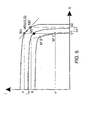
- the first point M1 (v1,i1) is the present operation point. It is characterized by its voltage v1 which is always at the value of the preceding PMP, the "old" PMP, but with a current i1 that has changed, as it is not the new PMP or the old PMP.
- the measurement of the difference between the current values allows us to find out where the new PMP is found at the same time that it indicates an estimate of its distance. If the difference is positive, the voltage of the new PMP is also larger than that of the old PMP; while if it is negative, it will have a lower voltage.
- the method for controlling changes the working point of the solar panel imposing a positive step (if the difference i1 - i pmp "old” is positive) or negative (if the difference i1 - i pmp "old” is negative) to the reference of the power regulator.
- the amplitude of this step is proportional, with a constant k v selected by the user, to the amplitude of the difference of said current values.
- the second point M2(v2,i2) is necessary to find the coordinates of the new PMP.
- the third point M3(v3,i3) is calculated as a result by the processor, its coordinates being those of the midpoint of the segment M1M2.
- v 3 nAkT q ⁇ Log ⁇ 1 + mi SC - i 3 mi R ⁇ naLog ⁇ i SC - i 3 i R
- Another aspect of the invention is a control circuit of the Point of Maximum Power for solar energy sources, whose electric characteristic has a single PMP for working conditions wherein the solar source operates in accordance with each moment, which comprises:
- the calculation module provides storage means, a memory integrated or not in the programmable electronic device, capable of saving the necessary data in the establishment of the voltage V pmp .
- Said calculation module which can be integrated or not in the power conditioning unit, incorporates digital analogue converters to receive the measurement points of the electric characteristic and digital analogue converters to deliver the reference voltage to the power cell of said power conditioning unit, which constitute an interface with the solar source.
- the programmable electronic device which can be a general purpose microprocessor, a digital signal microprocessor (DSP), an application specific integrated circuit (ASCI), a programmable card (FPGA) or any other combination of the foregoing, is in charge of establishing the values continuously updating from the working point of the solar panel or from the equivalent energy source, accessing the real electric characteristics of the source and obtaining therefrom, with one, two or at most three measurement points, the voltage of the PMP.
- This voltage is that which is used as a reference of the power conditioning unit, which conventionally can have a converted structure of series type or parallel type, for example with topologies of known power regulators such as S3R or ASR.
- the data of the manufacturer and relative to the configuration of the solar panel, together with the measurements of its electric characteristic, are saved in a memory or database, with the aim that the programmable electronic device can access them and execute the specific calculations and iterative algorithms in order to solve the non-linear equations implicated in the control method set out.
- the circuit comprises means of receiving the instantaneous measurements and a current pick-up adapted to measure the value of the current in real time.
- the programmable electronic device When the difference between the value of the current in real time and that of the current I pmp at the Point of Maximum Power (PMP) surpasses a pre-determined limit, the programmable electronic device is thus configured to adjust the new working coordinates returning to execute the PMP controlling method, considerably fast since it only requires a single measurement point always in direction of the final value of the new PMP, in the characteristic curve of the source.
- PMP Point of Maximum Power
- the source (1) is connected to a user loading network (4), by means of a power conditioning unit (2), as is illustrated in Figures 2 and 3 , respectively, depending on whether the power regulator is configured with a power cell (3) in series or in parallel.
- v MPP naLog ⁇ mi SC - i MPP mi R
- the calculation module (5) has at least one microprocessor which processes data coming from a database and the values of the coordinates of the working point of the solar source (1), in order to establish the reference voltage (V pmp ) which is that of the Point of Maximum Power (PMP).
- said source (1) is forced to work permanently at the Point of Maximum Power (PMP), if the user of the network requires.
- PMP Point of Maximum Power
- the microprocessor of the calculation module (5) calculates a series of parameters necessary in the previous equation, namely:
- the calculation of the first parameter (i R ) i.e., the dark current is executed by the microprocessor at the beginning, when the solar cells are new; afterwards, the valued of said dark current is re-calculated or updated periodically and stored in the memory of the microprocessor as explained below.
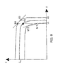
- a point (M0) is highlighted corresponding to the "old" Point of Maximum Power (5), having single measurement point (M2, M'2) depending on whether the power of the panel has increased or decreased.
- the point M2 is to the right of M1, if the current is greater than that of the "old” PMP, and M'2 is situated to the left of M'1 otherwise.
- the microprocessor organizes the calculation of the coordinates of the third measurement point (M3, M'3), situated at the midpoint of the segment M1M2 or M'1M'2, wherefrom the coordinates of the "new" Point of Maximum Power (PMP) are determined.
- M3, M'3 the third measurement point
- the change of the value of the current cause the microprocessor to receive the instruction to search for the coordinates of the new PMP. It must be borne in mind that the coordinates of the operation point of the solar panel are known at all times by the microprocessor.
- the microprocessor can take as initial value in its calculations of said dark current (i R ), that obtained from certain data of the manufacturer of the solar source (1), which are: the short circuit current in normal pressure and temperature conditions, i.e., at one atmosphere and 27 °C, the current and voltage at the Point of Maximum Power (PMP) in said conditions and the open circuit voltage (v oc ) of the source (1).
- the microprocessor calculates in the initialization of the first moment of use of the system the value of the dark current (i R ).
- this initial value of the dark current (i R ) is introduced, as an input of the microprocessor to perform the first calculation of the Point of Maximum Power (PMP), this value can be periodically updated, for example, every one hundred calculations of the Point of Maximum Power (PMP).
- PMP Point of Maximum Power
- the production of the other two parameters (mi sc ,na) basically consists of solving a system of equations with two unknown quantities, which is achieved by processing in the calculation module (5) the data available from two working points (M 1 , M 2 ) of the electric characteristic, as is shown in Figure 6 , where the first point (M 1 ) is defined by coordinates (v1, i1).
- the voltage (v 1 ) of said first point (M 1 ) corresponds to the "old” or already known value of at the Point of Maximum Power (PMP), i.e., at the "old” point (M 0 ), but the current (i 1 ) is different from that corresponding to the Point of Maximum Power (PMP) because it varies as the conditions of the solar lighting change.
- PMP Point of Maximum Power
- the second point (M 2 ) is measured in the electric characteristic, whose coordinates (v 2 , i 2 ) are drawn in Figure 6 ).
- This second point (M 2 ) corresponds to in intermediate point directly in the vicinity of the Point of Maximum Power (PMP) or is already the same, obtaining according to the sign of the variation between the previous value of the current stored in the memory and the value measured of the current, which when it is negative can correspond to another second point (M' 2 ).
- PMP Point of Maximum Power
- a second point (M 2 ) in the electric characteristic measured a second equation can be established together with (2.27) to calculate the two parameters (mi sc ,na), or what is the same, the unknown values of the form factor of the characteristic (A) and the short circuit current (i sc ).
- i SC 1 m ( i 1 + i R ⁇ exp q nAkT ⁇ v 1 - 1
- the calculation at the Point of Maximum Power (PMP) of the current (i pmp ), is translated in obtaining the intersection point between the curves (f 1 ) and (f 2 ), which is single and corresponds to the value of current which makes becomes highest in the power function (P) and is the searched for Point of Maximum Power (PMP), in accordance with that illustrated in Figure 1 .
- the calculation module (5) is capable of continuously predicting the coordinates (V pmp , I pmp ), without disturbing the voltage supplied to the user loading network (4), which can be made of a bank of batteries, a motor or a DC pump,...
- the power conditioning unit (2) regulates, following the reference signal supplied by the calculation module (5) and which establishes an interface with the solar source and said power conditioning unit (2).
- This independent calculation module (5) delivers in real time to the power cell (3) a value of voltage (V pmp ) in correspondence, i.e., rigorously proportional or equal to the instantaneous value of the voltage of the Point of Maximum Power (PMP) in terms of amplitude and length of time.
- the voltage thus regulated is the input voltage of a power cell (3) of type series or the voltage supplied to the user network (4) by a power structure of parallel type.
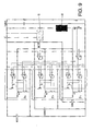
- FIG. 7 represents the particular case wherein the power conditioning unit (2) has a structure of a sequential switching parallel regulator, for example of the known type S3R.
- the basic principle is to carry out an electronic switching which connected in parallel with a photovoltaic panel operates in two ways: in open circuit and in short circuit.
- the S3R regulator isolates the solar panels from the users during a part of the switching period and forces said solar panels, generators of currents (I GS1 , I GS2 ..., I GSn ) to work in a regulated voltage, such as that of the PMP obtained in this invention.
- the advantage that the use of the S3R regulator supposes is the minimization of the power dissipated in all the switches.
- the solar panel will be good in short circuit and, therefore, the short circuit current (i sc ) is automatically known, or, supplying energy to the user loading network (4) through the diode connected in series.
- the coordinates of the first working point (M1) are also automatically known. And, as a consequence, all the parameters are automatically available upon finding out the coordinates of said first working point (M1).
- the S3R regulator can also be applied to a structure in series, forcing the solar panels to operate at the reference voltage in open circuit.
- the microprocessor can easily calculate the solution of the two equation system (2.37) and (2.38) in order to obtain the first point (M1) of the characteristic of the solar source (1).
- the calculation of the rest of the parameters of the electric characteristic do not depend on the voltage and current measurements of the second point (M2) to generate the straight line M1'M2 or M1"M2" seen in Figure 6 .
- type S4R Another possible topology that can be used to implement the power conditioning unit (2) is that known as type S4R, represented as a block diagram in Figure 8 , with the connection to a battery (6), a battery control (7) and a battery porter (8).
- This power conditioning unit (2) type S4R includes a series power cell (3') and a parallel power cell (3").
- S4R units (2a, 2b,..., 2n) can be connected following the diagram of Figure 9 , controlled by a single calculation module (5).
- each S4R unit (2a, 2b,..., 2n)
- the battery porter (8) which functions in sample mode and isolates that battery (6) from the solar panels and from the network.
Landscapes
- Engineering & Computer Science (AREA)
- Physics & Mathematics (AREA)
- Electromagnetism (AREA)
- General Physics & Mathematics (AREA)
- Radar, Positioning & Navigation (AREA)
- Automation & Control Theory (AREA)
- Life Sciences & Earth Sciences (AREA)
- Sustainable Development (AREA)
- Sustainable Energy (AREA)
- Power Engineering (AREA)
- Control Of Electrical Variables (AREA)
- Charge And Discharge Circuits For Batteries Or The Like (AREA)
Applications Claiming Priority (2)
| Application Number | Priority Date | Filing Date | Title |
|---|---|---|---|
| ES200600843 | 2006-03-31 | ||
| PCT/ES2007/000184 WO2007113358A1 (es) | 2006-03-31 | 2007-03-30 | Circuito y procedimiento de control del punto de potencia máxima para fuentes de energía solar y generador solar que incorpora dicho circuito |
Publications (1)
| Publication Number | Publication Date |
|---|---|
| EP2023227A1 true EP2023227A1 (de) | 2009-02-11 |
Family
ID=38563139
Family Applications (1)
| Application Number | Title | Priority Date | Filing Date |
|---|---|---|---|
| EP07730424A Withdrawn EP2023227A1 (de) | 2006-03-31 | 2007-03-30 | Schaltung und verfahren zur überwachung des punkts maximaler leistung für solarenergiequellen und solargenerator mit der schaltung |
Country Status (10)
| Country | Link |
|---|---|
| US (1) | US20100176773A1 (de) |
| EP (1) | EP2023227A1 (de) |
| JP (1) | JP2009531762A (de) |
| KR (1) | KR20090009220A (de) |
| CN (1) | CN101416135A (de) |
| AU (1) | AU2007233591A1 (de) |
| CA (1) | CA2647777A1 (de) |
| IL (1) | IL194426A0 (de) |
| MX (1) | MX2008012512A (de) |
| WO (1) | WO2007113358A1 (de) |
Cited By (5)
| Publication number | Priority date | Publication date | Assignee | Title |
|---|---|---|---|---|
| WO2011076707A2 (en) | 2009-12-23 | 2011-06-30 | Control Techniques Ltd | Voltage compensation |
| WO2012010203A1 (en) * | 2010-07-21 | 2012-01-26 | Mppc Technology | Process to operate continuously a solar array to its maximum power in variable shadowing conditions and device needed to carry it out |
| CN102403928A (zh) * | 2010-12-27 | 2012-04-04 | 董密 | 一种光伏电能优化的最大功率点跟踪控制方法及其系统 |
| CN113485517A (zh) * | 2021-07-14 | 2021-10-08 | 四川大学 | 一种局部遮蔽条件下光伏阵列最大功率点跟踪方法 |
| US11567551B2 (en) | 2020-07-28 | 2023-01-31 | Rohde & Schwarz Gmbh & Co. Kg | Adaptive power supply |
Families Citing this family (81)
| Publication number | Priority date | Publication date | Assignee | Title |
|---|---|---|---|---|
| US11881814B2 (en) | 2005-12-05 | 2024-01-23 | Solaredge Technologies Ltd. | Testing of a photovoltaic panel |
| US10693415B2 (en) | 2007-12-05 | 2020-06-23 | Solaredge Technologies Ltd. | Testing of a photovoltaic panel |
| US7900361B2 (en) | 2006-12-06 | 2011-03-08 | Solaredge, Ltd. | Current bypass for distributed power harvesting systems using DC power sources |
| US8963369B2 (en) | 2007-12-04 | 2015-02-24 | Solaredge Technologies Ltd. | Distributed power harvesting systems using DC power sources |
| US8319471B2 (en) | 2006-12-06 | 2012-11-27 | Solaredge, Ltd. | Battery power delivery module |
| US11309832B2 (en) | 2006-12-06 | 2022-04-19 | Solaredge Technologies Ltd. | Distributed power harvesting systems using DC power sources |
| US11296650B2 (en) | 2006-12-06 | 2022-04-05 | Solaredge Technologies Ltd. | System and method for protection during inverter shutdown in distributed power installations |
| US9088178B2 (en) | 2006-12-06 | 2015-07-21 | Solaredge Technologies Ltd | Distributed power harvesting systems using DC power sources |
| US8618692B2 (en) | 2007-12-04 | 2013-12-31 | Solaredge Technologies Ltd. | Distributed power system using direct current power sources |
| US8384243B2 (en) | 2007-12-04 | 2013-02-26 | Solaredge Technologies Ltd. | Distributed power harvesting systems using DC power sources |
| US11735910B2 (en) | 2006-12-06 | 2023-08-22 | Solaredge Technologies Ltd. | Distributed power system using direct current power sources |
| US8947194B2 (en) | 2009-05-26 | 2015-02-03 | Solaredge Technologies Ltd. | Theft detection and prevention in a power generation system |
| US8013472B2 (en) | 2006-12-06 | 2011-09-06 | Solaredge, Ltd. | Method for distributed power harvesting using DC power sources |
| US8473250B2 (en) | 2006-12-06 | 2013-06-25 | Solaredge, Ltd. | Monitoring of distributed power harvesting systems using DC power sources |
| US8816535B2 (en) | 2007-10-10 | 2014-08-26 | Solaredge Technologies, Ltd. | System and method for protection during inverter shutdown in distributed power installations |
| US11569659B2 (en) | 2006-12-06 | 2023-01-31 | Solaredge Technologies Ltd. | Distributed power harvesting systems using DC power sources |
| US11855231B2 (en) | 2006-12-06 | 2023-12-26 | Solaredge Technologies Ltd. | Distributed power harvesting systems using DC power sources |
| US9112379B2 (en) | 2006-12-06 | 2015-08-18 | Solaredge Technologies Ltd. | Pairing of components in a direct current distributed power generation system |
| US11888387B2 (en) | 2006-12-06 | 2024-01-30 | Solaredge Technologies Ltd. | Safety mechanisms, wake up and shutdown methods in distributed power installations |
| US8319483B2 (en) | 2007-08-06 | 2012-11-27 | Solaredge Technologies Ltd. | Digital average input current control in power converter |
| US11687112B2 (en) | 2006-12-06 | 2023-06-27 | Solaredge Technologies Ltd. | Distributed power harvesting systems using DC power sources |
| US9130401B2 (en) | 2006-12-06 | 2015-09-08 | Solaredge Technologies Ltd. | Distributed power harvesting systems using DC power sources |
| US12316274B2 (en) | 2006-12-06 | 2025-05-27 | Solaredge Technologies Ltd. | Pairing of components in a direct current distributed power generation system |
| EP2232690B1 (de) | 2007-12-05 | 2016-08-31 | Solaredge Technologies Ltd. | Parallel geschaltete umrichter |
| US11264947B2 (en) | 2007-12-05 | 2022-03-01 | Solaredge Technologies Ltd. | Testing of a photovoltaic panel |
| EP3561881A1 (de) | 2007-12-05 | 2019-10-30 | Solaredge Technologies Ltd. | Prüfung eines fotovoltaikplanels |
| WO2009072075A2 (en) | 2007-12-05 | 2009-06-11 | Solaredge Technologies Ltd. | Photovoltaic system power tracking method |
| US8049523B2 (en) | 2007-12-05 | 2011-11-01 | Solaredge Technologies Ltd. | Current sensing on a MOSFET |
| EP3496258B1 (de) | 2007-12-05 | 2025-02-05 | Solaredge Technologies Ltd. | Sicherheitsmechanismus in verteilten strominstallationen |
| EP4145691A1 (de) | 2008-03-24 | 2023-03-08 | Solaredge Technologies Ltd. | Schaltwandler mit einem hilfskommutierungsschaltkreis zur nullstromschaltung |
| EP3121922B1 (de) | 2008-05-05 | 2020-03-04 | Solaredge Technologies Ltd. | Gleichstromleistungskombinierer |
| JP5419252B2 (ja) * | 2008-06-10 | 2014-02-19 | 聖士郎 宗平 | 最大電力スイッチングコンバーター |
| US8630098B2 (en) | 2008-06-12 | 2014-01-14 | Solaredge Technologies Ltd. | Switching circuit layout with heatsink |
| JP5026374B2 (ja) * | 2008-09-05 | 2012-09-12 | 日本電信電話株式会社 | 電力制御方法および電力制御装置 |
| WO2010097093A1 (en) * | 2009-02-24 | 2010-09-02 | Mppc Technology | Process and device to operate continuously a solar array to its maximum power |
| FR2944647B1 (fr) * | 2009-04-17 | 2011-08-05 | Commissariat Energie Atomique | Procede de diagnostic de la defaillance d'un generateur photovoltaique |
| JP2012527767A (ja) | 2009-05-22 | 2012-11-08 | ソラレッジ テクノロジーズ リミテッド | 電気絶縁された熱放散接続箱 |
| US8303349B2 (en) | 2009-05-22 | 2012-11-06 | Solaredge Technologies Ltd. | Dual compressive connector |
| US8690110B2 (en) | 2009-05-25 | 2014-04-08 | Solaredge Technologies Ltd. | Bracket for connection of a junction box to photovoltaic panels |
| FR2951886B1 (fr) * | 2009-10-23 | 2016-02-05 | Commissariat Energie Atomique | Commande avec ralentissement de l'ouverture d'un interrupteur electronique |
| US12418177B2 (en) | 2009-10-24 | 2025-09-16 | Solaredge Technologies Ltd. | Distributed power system using direct current power sources |
| US8710699B2 (en) | 2009-12-01 | 2014-04-29 | Solaredge Technologies Ltd. | Dual use photovoltaic system |
| KR101036098B1 (ko) * | 2009-12-04 | 2011-05-19 | 삼성에스디아이 주식회사 | 최대 전력점 추종 컨버터 및 그 방법 |
| US8766696B2 (en) | 2010-01-27 | 2014-07-01 | Solaredge Technologies Ltd. | Fast voltage level shifter circuit |
| US10673229B2 (en) | 2010-11-09 | 2020-06-02 | Solaredge Technologies Ltd. | Arc detection and prevention in a power generation system |
| GB2485527B (en) | 2010-11-09 | 2012-12-19 | Solaredge Technologies Ltd | Arc detection and prevention in a power generation system |
| US10230310B2 (en) | 2016-04-05 | 2019-03-12 | Solaredge Technologies Ltd | Safety switch for photovoltaic systems |
| US10673222B2 (en) | 2010-11-09 | 2020-06-02 | Solaredge Technologies Ltd. | Arc detection and prevention in a power generation system |
| GB2486408A (en) | 2010-12-09 | 2012-06-20 | Solaredge Technologies Ltd | Disconnection of a string carrying direct current |
| GB2483317B (en) | 2011-01-12 | 2012-08-22 | Solaredge Technologies Ltd | Serially connected inverters |
| CN102156504B (zh) * | 2011-04-14 | 2013-10-23 | 矽力杰半导体技术(杭州)有限公司 | 一种太阳能电池板最大功率跟踪装置、跟踪方法以及应用其的太阳能供电装置 |
| TWI467357B (zh) * | 2011-04-29 | 2015-01-01 | Au Optronics Corp | 電源管理系統與電源管理方法 |
| US8570005B2 (en) | 2011-09-12 | 2013-10-29 | Solaredge Technologies Ltd. | Direct current link circuit |
| GB2498365A (en) | 2012-01-11 | 2013-07-17 | Solaredge Technologies Ltd | Photovoltaic module |
| GB2498790A (en) | 2012-01-30 | 2013-07-31 | Solaredge Technologies Ltd | Maximising power in a photovoltaic distributed power system |
| GB2498791A (en) | 2012-01-30 | 2013-07-31 | Solaredge Technologies Ltd | Photovoltaic panel circuitry |
| US9853565B2 (en) | 2012-01-30 | 2017-12-26 | Solaredge Technologies Ltd. | Maximized power in a photovoltaic distributed power system |
| GB2499991A (en) | 2012-03-05 | 2013-09-11 | Solaredge Technologies Ltd | DC link circuit for photovoltaic array |
| CN102637056B (zh) * | 2012-03-28 | 2014-09-17 | 浙江理工大学 | 一种维持光伏发电系统最大功率点的方法 |
| DE102012102932B4 (de) * | 2012-04-04 | 2018-03-29 | Sma Solar Technology Ag | Verfahren und Vorrichtung zur Signalisierung einer Teilverschattung eines Photovoltaikgenerators |
| EP3499695B1 (de) | 2012-05-25 | 2024-09-18 | Solaredge Technologies Ltd. | Schaltung für verbundene gleichstromquellen |
| US10115841B2 (en) | 2012-06-04 | 2018-10-30 | Solaredge Technologies Ltd. | Integrated photovoltaic panel circuitry |
| US9246383B2 (en) * | 2012-10-05 | 2016-01-26 | Linear Technology Corporation | System and method for input voltage regulation of switch mode supplies implementing burst mode operation |
| CN103123514B (zh) * | 2013-02-26 | 2014-11-12 | 浙江工业大学 | 光伏阵列多峰最大功率点跟踪方法 |
| US9548619B2 (en) | 2013-03-14 | 2017-01-17 | Solaredge Technologies Ltd. | Method and apparatus for storing and depleting energy |
| US9941813B2 (en) | 2013-03-14 | 2018-04-10 | Solaredge Technologies Ltd. | High frequency multi-level inverter |
| EP2779251B1 (de) | 2013-03-15 | 2019-02-27 | Solaredge Technologies Ltd. | Umgehungsmechanismus |
| CN103236803B (zh) * | 2013-04-11 | 2015-04-08 | 深圳晶福源科技股份有限公司 | 光伏逆变器的mppt控制方法 |
| US9318974B2 (en) | 2014-03-26 | 2016-04-19 | Solaredge Technologies Ltd. | Multi-level inverter with flying capacitor topology |
| CN104317347A (zh) * | 2014-10-20 | 2015-01-28 | 西北工业大学 | 具有最大功率点跟踪功能的s4r电源控制方法及装置 |
| US10599113B2 (en) | 2016-03-03 | 2020-03-24 | Solaredge Technologies Ltd. | Apparatus and method for determining an order of power devices in power generation systems |
| CN107153212B (zh) | 2016-03-03 | 2023-07-28 | 太阳能安吉科技有限公司 | 用于映射发电设施的方法 |
| US11081608B2 (en) | 2016-03-03 | 2021-08-03 | Solaredge Technologies Ltd. | Apparatus and method for determining an order of power devices in power generation systems |
| US11177663B2 (en) | 2016-04-05 | 2021-11-16 | Solaredge Technologies Ltd. | Chain of power devices |
| US11018623B2 (en) | 2016-04-05 | 2021-05-25 | Solaredge Technologies Ltd. | Safety switch for photovoltaic systems |
| US12057807B2 (en) | 2016-04-05 | 2024-08-06 | Solaredge Technologies Ltd. | Chain of power devices |
| CN107450651B (zh) * | 2017-09-18 | 2019-03-15 | 张丽君 | 光伏发电系统最大功率点捕捉系统的控制方法 |
| JP7389977B2 (ja) * | 2018-03-29 | 2023-12-01 | 国立研究開発法人宇宙航空研究開発機構 | 電力制御システム |
| CN109787289B (zh) | 2019-03-15 | 2021-08-13 | 矽力杰半导体技术(杭州)有限公司 | 功率变换系统、光伏优化器及功率跟踪方法 |
| WO2022026182A1 (en) * | 2020-07-29 | 2022-02-03 | Cirrus Logic International Semiconductor Ltd. | Maintaining operation of a power converter within a stable region of a power curve or that power converter |
| KR102554154B1 (ko) * | 2021-05-21 | 2023-07-12 | 주식회사 쏠에너지 | 태양광 모듈의 출력 보상 장치 |
Family Cites Families (9)
| Publication number | Priority date | Publication date | Assignee | Title |
|---|---|---|---|---|
| JP2771096B2 (ja) * | 1993-06-11 | 1998-07-02 | キヤノン株式会社 | 電力制御装置、電力制御方法及び電力発生装置 |
| JPH0962387A (ja) * | 1995-08-29 | 1997-03-07 | Canon Inc | 電池電源の電力制御方法及び装置並びに電池電源システム |
| JP3359206B2 (ja) * | 1995-10-31 | 2002-12-24 | キヤノン株式会社 | 電池電源の電力制御装置 |
| JP4042943B2 (ja) * | 1999-07-23 | 2008-02-06 | ヤマハ発動機株式会社 | 太陽電池の制御装置及び太陽電池の制御方法 |
| JP3394996B2 (ja) * | 2001-03-09 | 2003-04-07 | 独立行政法人産業技術総合研究所 | 最大電力動作点追尾方法及びその装置 |
| FR2844890B1 (fr) * | 2002-09-19 | 2005-01-14 | Cit Alcatel | Circuit de conditionnement pour une source de puissance au point de puissance maximum, generateur solaire et procede de conditionnement |
| JP4791689B2 (ja) * | 2003-10-06 | 2011-10-12 | パナソニック株式会社 | 電源装置 |
| US7839022B2 (en) * | 2004-07-13 | 2010-11-23 | Tigo Energy, Inc. | Device for distributed maximum power tracking for solar arrays |
| US20080257397A1 (en) * | 2007-04-17 | 2008-10-23 | John Stanley Glaser | System, method, and apparatus for extracting power from a photovoltaic source of electrical energy |
-
2007
- 2007-03-30 KR KR1020087026648A patent/KR20090009220A/ko not_active Withdrawn
- 2007-03-30 EP EP07730424A patent/EP2023227A1/de not_active Withdrawn
- 2007-03-30 WO PCT/ES2007/000184 patent/WO2007113358A1/es not_active Ceased
- 2007-03-30 JP JP2009502125A patent/JP2009531762A/ja active Pending
- 2007-03-30 MX MX2008012512A patent/MX2008012512A/es active IP Right Grant
- 2007-03-30 US US12/294,955 patent/US20100176773A1/en not_active Abandoned
- 2007-03-30 CN CNA2007800124197A patent/CN101416135A/zh active Pending
- 2007-03-30 AU AU2007233591A patent/AU2007233591A1/en not_active Abandoned
- 2007-03-30 CA CA002647777A patent/CA2647777A1/en not_active Abandoned
-
2008
- 2008-09-28 IL IL194426A patent/IL194426A0/en unknown
Non-Patent Citations (1)
| Title |
|---|
| See references of WO2007113358A1 * |
Cited By (7)
| Publication number | Priority date | Publication date | Assignee | Title |
|---|---|---|---|---|
| WO2011076707A2 (en) | 2009-12-23 | 2011-06-30 | Control Techniques Ltd | Voltage compensation |
| WO2011076707A3 (en) * | 2009-12-23 | 2011-08-18 | Control Techniques Ltd | Voltage compensation |
| WO2012010203A1 (en) * | 2010-07-21 | 2012-01-26 | Mppc Technology | Process to operate continuously a solar array to its maximum power in variable shadowing conditions and device needed to carry it out |
| CN102403928A (zh) * | 2010-12-27 | 2012-04-04 | 董密 | 一种光伏电能优化的最大功率点跟踪控制方法及其系统 |
| CN102403928B (zh) * | 2010-12-27 | 2014-07-23 | 董密 | 一种光伏电能优化的最大功率点跟踪控制方法及其系统 |
| US11567551B2 (en) | 2020-07-28 | 2023-01-31 | Rohde & Schwarz Gmbh & Co. Kg | Adaptive power supply |
| CN113485517A (zh) * | 2021-07-14 | 2021-10-08 | 四川大学 | 一种局部遮蔽条件下光伏阵列最大功率点跟踪方法 |
Also Published As
| Publication number | Publication date |
|---|---|
| AU2007233591A1 (en) | 2007-10-11 |
| US20100176773A1 (en) | 2010-07-15 |
| CA2647777A1 (en) | 2007-10-11 |
| KR20090009220A (ko) | 2009-01-22 |
| MX2008012512A (es) | 2008-12-16 |
| WO2007113358A1 (es) | 2007-10-11 |
| JP2009531762A (ja) | 2009-09-03 |
| CN101416135A (zh) | 2009-04-22 |
| IL194426A0 (en) | 2009-08-03 |
Similar Documents
| Publication | Publication Date | Title |
|---|---|---|
| EP2023227A1 (de) | Schaltung und verfahren zur überwachung des punkts maximaler leistung für solarenergiequellen und solargenerator mit der schaltung | |
| Salas et al. | Review of the maximum power point tracking algorithms for stand-alone photovoltaic systems | |
| Zhang et al. | Hybrid maximum power point tracking method based on iterative learning control and perturb & observe method | |
| Rekioua et al. | Tracking power photovoltaic system with sliding mode control strategy | |
| Xiao et al. | Real-time identification of optimal operating points in photovoltaic power systems | |
| Chang et al. | Coordinated frequency regulation using solar forecasting based virtual inertia control for islanded microgrids | |
| KR101598464B1 (ko) | 하이브리드 mppt제어에 의한 태양광발전시스템의 효율개선 방법 | |
| Murtaza et al. | A duty cycle optimization based hybrid maximum power point tracking technique for photovoltaic systems | |
| Zhang et al. | A MPPT method based on improved fibonacci search photovoltaic array | |
| Kumar et al. | Design and analysis of nonlinear controller for a standalone photovoltaic system using Lyapunov stability theory | |
| Inthamoussou et al. | A fast and robust closed-loop photovoltaic MPPT approach based on sliding mode techniques | |
| Ma et al. | Improving power-conversion efficiency via a hybrid MPPT approach for photovoltaic systems | |
| Kahoul et al. | A comprehensive simulator for assessing the reliability of a photovoltaic panel peak power tracking system | |
| EP2722725B1 (de) | Vorrichtung zur Verfolgung eines Punktes maximaler Leistung einer Stromquelle | |
| EP2513736B1 (de) | Verfahren zum erhalt von informationen zur bestimmung der eigenschaft einer stromquelle | |
| Mbarki et al. | Comparative study of some maximum power point tracking algorithms | |
| Ayop et al. | Computation of current-resistance photovoltaic model using reverse triangular number for photovoltaic emulator application | |
| Jamil et al. | Maximum power point tracking of a solar system using state space averaging for wireless sensor network | |
| Zhang et al. | An advanced maximum power point capturing technique with supercapacitor for PV system | |
| Kim et al. | Improving the efficiency of a photovoltaic system using a hybrid control method based on a DPP structure | |
| Mehta et al. | A Novel Maximum Power Point Estimation Algorithm for PV System Using Real-Time Short Circuit Current Calculation | |
| Stitou et al. | Adaptive high gain observer for photovoltaic systems | |
| Dubewar et al. | Comparative study of photovoltaic array maximum power point tracking techniques | |
| Erol et al. | Gain-phase margins based stability analysis of time delayed hybrid load frequency control system | |
| Vidal et al. | An adaptive signal processing framework for PV power maximization |
Legal Events
| Date | Code | Title | Description |
|---|---|---|---|
| PUAI | Public reference made under article 153(3) epc to a published international application that has entered the european phase |
Free format text: ORIGINAL CODE: 0009012 |
|
| 17P | Request for examination filed |
Effective date: 20081016 |
|
| AK | Designated contracting states |
Kind code of ref document: A1 Designated state(s): AT BE BG CH CY CZ DE DK EE ES FI FR GB GR HU IE IS IT LI LT LU LV MC MT NL PL PT RO SE SI SK TR |
|
| AX | Request for extension of the european patent |
Extension state: AL BA HR MK RS |
|
| RIN1 | Information on inventor provided before grant (corrected) |
Inventor name: CAPEL, ANTOINE |
|
| RAP1 | Party data changed (applicant data changed or rights of an application transferred) |
Owner name: MPPC TECHNOLOGY |
|
| STAA | Information on the status of an ep patent application or granted ep patent |
Free format text: STATUS: THE APPLICATION IS DEEMED TO BE WITHDRAWN |
|
| 18D | Application deemed to be withdrawn |
Effective date: 20111001 |