EP2722725B1 - Vorrichtung zur Verfolgung eines Punktes maximaler Leistung einer Stromquelle - Google Patents
Vorrichtung zur Verfolgung eines Punktes maximaler Leistung einer Stromquelle Download PDFInfo
- Publication number
- EP2722725B1 EP2722725B1 EP12188687.3A EP12188687A EP2722725B1 EP 2722725 B1 EP2722725 B1 EP 2722725B1 EP 12188687 A EP12188687 A EP 12188687A EP 2722725 B1 EP2722725 B1 EP 2722725B1
- Authority
- EP
- European Patent Office
- Prior art keywords
- voltage
- power source
- power
- value
- estimated
- Prior art date
- Legal status (The legal status is an assumption and is not a legal conclusion. Google has not performed a legal analysis and makes no representation as to the accuracy of the status listed.)
- Not-in-force
Links
Images



Classifications
-
- G—PHYSICS
- G05—CONTROLLING; REGULATING
- G05F—SYSTEMS FOR REGULATING ELECTRIC OR MAGNETIC VARIABLES
- G05F1/00—Automatic systems in which deviations of an electric quantity from one or more predetermined values are detected at the output of the system and fed back to a device within the system to restore the detected quantity to its predetermined value or values, i.e. retroactive systems
- G05F1/66—Regulating electric power
- G05F1/67—Regulating electric power to the maximum power available from a generator, e.g. from solar cell
Definitions
- the present invention relates generally to a device for tracking a maximum power point of a power source like a photovoltaic cell or an array of cells or a fuel cell.
- a photovoltaic cell directly converts solar energy into electrical energy.
- the electrical energy produced by the photovoltaic cell can be extracted over time and used in the form of electric power.
- the direct electric power provided by the photovoltaic cell is provided to energy conversion devices like DC-DC up/down converter circuits and/or DC/AC inverter circuits.
- the current-voltage characteristics of photovoltaic cells cause the output power to change nonlinearly with the current drawn from photovoltaic cells.
- the power-voltage curve changes according to climatic variations like light radiation levels and operation temperatures.
- I pv I sc (L) - I o (T) (exp(V pv /V br )-1), where I sc is the shortcut circuit current of the photovoltaic cell under irradiance L, and Io is the cell body diode current under temperature T, V br is the breakdown voltage of the PV cell, which is independent on irradiance and has low variation with cell temperature.
- the near optimal point at which to operate photovoltaic cells or arrays of cells is at or near the region of the current-voltage curve where the power is greatest. This point is denominated as the Maximum Power Point (MPP).
- MPP Maximum Power Point
- the location of the Maximum Power Point is not known, but can be located, either through calculation models or by search algorithms.
- the Maximum Power Point also changes according to climatic variations.
- Maximum Power point tracking algorithm uses fixed voltage step in order to track the maximum power point, the use of fixed voltage steps leads to some problems. If the voltage step is big, loss of the power provided by the power source occurs due to large oscillations around the maximum power point value. If the voltage step is small, the convergence to the maximum power point value is slow.
- the present invention aims at providing a device which enables to provide a tracking of the maximum power point which is robust to climatic variations and with a limited increase of the duration of the perturbation cycle.
- the present invention concerns a device for tracking the maximum power point of a power source, the device comprising:
- the present invention concerns also a method for tracking the maximum power point of a power source, the method comprising the steps of:
- the voltage step is almost equal to the voltage difference between the first voltage and the voltage corresponding to the maximum power point.
- the device converges faster to the maximum power point.
- the tracking of the maximum power point is then robust to climatic variations.
- the voltage step is determined from a logarithm of one minus the estimated derivative of the power provided by the power source divided by the estimated current, the logarithm being divided by a parameter which is dependent of nominal characteristics of the power source.
- the determined step is equal to the voltage difference between the first voltage and the voltage corresponding to the maximum power point.
- the device can converge to the maximum power point in one step.
- the speed of acquisition of the maximum power point is greatly shortened. It should be noted that direct convergence to maximum power point can be obtained for any climatic conditions (L,T) without the need for climatic sensors.
- the parameter is further dependent of a coefficient comprised between one and two.
- the breakdown voltage may experience small variation due to unknown variations of the cell temperature, the breakdown voltage can be underestimated; leading the device to converge to the maximum power point in more than one step. Oscillations around the maximum power point can be minimised.
- the breakdown voltage of the power source can easily be determined at the setup of the power source.
- the proposed method will be effective at any irradiance conditions.
- the proposed method is effective at any cell temperature.
- the derivative of the power provided by the power source with respect to a change of the voltage provided by the power source is estimated from the power provided by the power source at the first voltage and from a power provided by the power source at another voltage.
- the derivative of the power provided by the power source with respect to a change of the voltage provided by the power source is estimated from:
- an accurate derivative of the power with voltage can be determined in ramping irradiance conditions.
- the method for tracking the maximum power point of a power source is effective under ramping conditions.
- the device for tracking the maximum power point is included in an energy conversion device.
- the energy conversion device can operate the power source to its maximum power point, in dynamic climatic conditions and with very fast tracking ability.
- the determined voltage step value is greater than a first predetermined positive value, the determined voltage step is set at the first predetermined positive value or if the determined voltage step value is lower than a second predetermined negative value, the determined voltage step is set at the second predetermined negative value.
- the voltage step is limited and the difference between the second voltage and the voltage corresponding to the maximum power point can be reduced. As a result, power losses can be minimised.
- the determined voltage step is set at a predetermined value which has the sign of the estimated derivative of the power provided by a voltage step used for determining the first voltage value.
- the voltage step is limited and the difference between the second voltage and the voltage corresponding to the maximum power point can be reduced. As a result, power losses can be minimised.
- Fig. 1 is an example of a curve representing the output current variations of a power source according to the output voltage of the power source.
- Fig. 1 On the horizontal axis of Fig. 1 , voltage values are shown. The voltage values are comprised between null value and the open circuit voltage V OC .
- Fig. 1 On the vertical axis of Fig. 1 , current values are shown. The current values are comprised between null value and the short circuit current I SC .
- the power source PV is a photovoltaic array
- Fig. 2 is an example of an energy conversion system wherein the present invention may be implemented.
- the energy conversion system is composed of a power source PV like a photovoltaic cell or an array of cells or a fuel cell connected to an energy conversion device Conv like a DC-DC step-down/step-up converter and/or a DC/AC converter also named inverter, which output provides electrical energy to the load Lo.
- a power source PV like a photovoltaic cell or an array of cells or a fuel cell
- an energy conversion device Conv like a DC-DC step-down/step-up converter and/or a DC/AC converter also named inverter, which output provides electrical energy to the load Lo.
- the energy conversion device Conv comprises at least one switch S.
- the power source PV provides current intended to the load Lo.
- the current I in and the voltage V in provided by the power source PV are converted by the energy conversion device Conv in output current I out and output voltage V out prior to be used by the load Lo.
- the energy conversion system further comprises a controller device 20.
- the controller device 20 determines, from successive power measurements, a regulation voltage value.
- the regulation voltage value is an estimation of the input voltage value which maximizes the energy produced by the power source PV.
- the controller device 20 controls the input voltage of the energy conversion device Conv, by controlling a duty cycle according to the regulation voltage value V pvref .
- the duty cycle drives the ON/OFF state of the at least one switch S of the energy conversion device Conv.
- the controller device 20 has, for example, an architecture based on components connected together by a bus 201 and a processor 200 controlled by the program related to the algorithm as disclosed in the Figs. 3a , 3b or 4 .
- processor 200 is, in a variant, implemented under the form of one or several dedicated integrated circuits which execute the same operations as the one executed by the processor 200 as disclosed hereinafter.
- the bus 201 links the processor 200 to a read only memory ROM 202, a random access memory RAM 203, an analogue to digital converter ADC 206 and to an interface 205.
- the read only memory ROM 202 contains instructions of the program related to the algorithm as disclosed in the Figs. 3a , 3b or 4 which are transferred, when the controller device 20 is powered on to the random access memory RAM 203.
- the RAM memory 203 contains registers intended to receive variables, and the instructions of the program related to the algorithm as disclosed in the Figs. 3a , 3b or 4 .
- the analogue to digital converter 206 is connected to the input and the output of the energy conversion device Conv and converts voltages and currents at the input and the output of the energy conversion device Conv into binary information.
- the processor 200 transfers, through interface module 205, the duty cycle D to be applied by the energy conversion device Conv.
- the controller device 20 comprises:
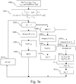
- Fig. 3 is an example of an algorithm for tracking the maximum power point of the power source according to a first mode of realization of the present invention.
- the present algorithm is executed by the processor 200 of the controller device 20.
- the processor 200 obtains the current I mp0 at maximum power at nominal characteristics of the power source PV, the short circuit current I sc0 at nominal characteristics of the power source PV, the voltage at maximum power V mp0 at nominal characteristics of the power source PV, the voltage v oc0 at open circuit at nominal characteristics of the power source and a coefficient coeff which is a predetermined value comprised between one and two.
- These current and voltage values are provided by the power source maker. These current and voltage values are stored in the ROM memory 202 or stored by the technical staff which installs the power source PV and the energy conversion device Conv.
- the coefficient coeff is stored in the ROM memory 202.
- the processor 200 obtains, according to the present invention, a parameter Param.
- the parameter Param is stored in the RAM memory 203 by the technical staff which installs the power source PV and the energy conversion device Conv.
- the processor 200 checks if a variable noted Idx is equal to one.
- variable Idx is set to one.
- step S303 If the variable Idx is equal to one, the processor 200 moves to step S303. Otherwise, the processor 200 moves to step S305.
- the processor 200 is controlling the voltage provided by the power source PV to a voltage value V vref which is equal to a voltage value V A and commands the analogue to digital converter ADC 206 in order to proceed to a measurement of the current I in at voltage V A .
- the processor 200 reads in memory 203 initial value of the voltage V A .
- the initial voltage of V A is equal to the null value or V OC0 .
- the processor 200 determines a power value P1 provided by the power source PV at voltage value V A .
- the processor 200 sets the voltage value V vref to a voltage value V B and controls, through the interface 206 and the switch S, the voltage provided by the power source PV to the voltage value V vref .
- the processor 200 reads in memory 203 initial value of the voltage V B .
- the initial voltage of V B is equal to the initial voltage VA plus a predetermined voltage step ⁇ V AB read in memory 203.
- the predetermined voltage step ⁇ V AB is set to one volt.
- step S304 the processor 200 steps the variable Idx to two.
- the processor 200 moves to step S314 and waits a predetermined time period ⁇ t.
- the predetermined time period is for example equal to one second.
- the predetermined time period is representative of the periodicity of execution of the maximum power point tracking algorithm.
- the processor 200 checks if a variable noted Idx is equal to two.
- step S306 If the variable Idx is equal to two, the processor 200 moves to step S306. Otherwise, the processor 200 moves to step S309.
- the processor 200 is controlling, through the interface 206 and the switch S, the voltage provided by the power source PV to a voltage value V vref which is equal to the voltage value V B and commands the analogue to digital converter ADC 206 in order to proceed to a measurement of the current I in at voltage V B .
- the processor 200 determines a power value P2 provided by the power source PV at V B .
- the processor 200 sets the voltage value V vref to the voltage value V A and controls, through the interface 206 and the switch S, the voltage provided by the power source PV to the voltage value V vref .
- step S308 the processor 200 steps the variable Idx to three.
- the processor 200 is controlling the voltage provided by the power source PV, through the interface 206 and the switch S, to a voltage value V vref which is equal to the voltage value V A and commands the analogue to digital converter ADC 206 in order to proceed to a measurement of the current I in at voltage V A .
- the processor 200 determines a power value P3 provided by the power source PV at V A .
- the processor 200 computes a voltage step value ⁇ V to be used for tracking the maximum power point.
- the voltage step value is computed from the estimated derivative of the power provided by the power source and from the estimated current.
- the processor 200 sets the variable V A to V A + ⁇ V and the variable V B to V B + ⁇ V.
- the processor 200 sets the voltage value V vref to the voltage value V A .
- the processor 200 sets the variable Idx to one.
- Fig. 3b is an example of an algorithm for determining the voltage step value according to the present invention.
- the processor 200 sets a variable P B to the value of P 2 and determines a mean value P A of P 3 and P 1 .
- P A P 1 + P 3 / 2
- the processor 200 checks if the estimated derivative of the power provided by the power source PV divided by the estimated current value is lower than one.
- step S320 If the estimated derivative of the power provided by the power source PV divided by the estimated current value is lower than one, the processor 200 moves to step S320. Otherwise, the processor 200 moves to step S319.
- the processor 200 determines the voltage step ⁇ V to be applied for tracking the maximum power point from a logarithm of one minus the estimated derivative of the power provided by the power source PV divided by the estimated current, the logarithm being divided by the parameter Param determined at step S301 which is dependent of nominal characteristics of the power source PV.
- step S318 avoids that error may occur in the calculation of the voltage step ⁇ V at step S320.
- the processor 200 checks if the voltage step ⁇ V determined at step S320 is upper than a first predetermined value.
- step S320 If the voltage step ⁇ V determined at step S320 is higher than the first predetermined value, the processor 200 moves to step S322. Otherwise, the processor 200 moves to step S324.
- the first predetermined value is comprised between five and fifteen volts.
- the first predetermined value is equal to ten volts.
- the processor 200 checks if the voltage step ⁇ V determined at step S320 is lower than a second predetermined value.
- step S320 If the voltage step ⁇ V determined at step S320 is lower than the second predetermined value, the processor 200 moves to step S325. Otherwise, the processor 200 moves to step S311 of Fig. 3a .
- the second predetermined value is comprised between minus five and minus fifteen volts.
- the second predetermined value is equal to minus ten volts.
- the processor 200 sets the voltage step ⁇ V at a third predetermined value, for example five volts, the sign of which is same as the sign of the estimated derivative dP/dV of the power provided by the power source.
- step S322 the processor 200 sets the voltage step ⁇ V at the first predetermined value and moves to step S311 of Fig. 3a .
- step S325 the processor 200 sets the voltage step ⁇ V at the second predetermined value and moves to step S311 of Fig. 3a .
- Fig. 4 is an example of an algorithm for tracking the maximum power point of the power source according to a second mode of realization of the present invention.
- the present algorithm is executed by the processor 200 of the controller device 20.
- the processor 200 obtains the current I mp0 at maximum power at nominal characteristics of the power source PV, the short circuit current I sc0 at nominal characteristics of the power source PV, the voltage at maximum power V mp0 at nominal characteristics of the power source PV, the voltage v oc0 at open circuit at nominal characteristics of the power source PV and a coefficient coeff which is a predetermined value comprised between one and two.
- These current and voltage values are provided by the power source maker. These current and voltage values are stored in the ROM memory 202 or stored in the RAM memory 203 by the technical staff which installs the power source PV and the energy conversion device Conv.
- the coefficient coeff is stored in the ROM memory 202.
- the processor 200 obtains, according to the present invention, a parameter Param.
- the parameter Param is stored in the RAM memory 203 by the technical staff which installs the power source PV and the energy conversion device Conv.
- the processor 200 is controlling, through the interface 206 and the switch S, the voltage provided by the power source PV to a voltage value V vref and commands the analogue to digital converter ADC 206 in order to proceed to a measurement of the current I in at voltage V vref .
- the processor 200 reads in memory 203 initial value of the voltage V vref .
- the initial voltage of V vref is equal to the null value or V OC0 .
- the processor 200 determines a power value P provided by the power source PV at V vref .
- the processor 200 sets the variable I to I in value and memorises the variable I.
- ⁇ Vprevious is equal to a predetermined value.
- the predetermined value is equal to one volt.
- the processor 200 checks if the estimated derivative of the power provided by the power source PV divided by the current I is lower than one.
- step S407 If the estimated derivative of the power provided by the power source PV divided by the current value I is lower than one, the processor 200 moves to step S407. Otherwise, the processor 200 moves to step S406.
- the processor 200 determines the voltage step ⁇ V to be applied for tracking the maximum power point from a logarithm of one minus the estimated derivative of the power provided by the power source PV divided by the estimated current, the logarithm being divided by the parameter Param which is dependent of nominal characteristics of the power source PV.
- step S405 avoids that error may occur in the calculation of the voltage step ⁇ V at step S407.
- the processor 200 sets the variable V ref to V ref + ⁇ V.
- the processor 200 set the variables ⁇ Vprevious to the value of ⁇ V determined at step S407 or at step S406 and Pprevious to the value of P measured at step S402.
- the processor 200 moves to step S410 and waits a predetermined time period ⁇ t.
- the predetermined time period is for example equal to one second.
- the predetermined time period is representative of the periodicity of execution of the maximum power point tracking algorithm.
- step S402 the processor 200 returns to step S402 already described.
- the processor 200 sets the voltage step ⁇ V at a predetermined value, for example five volts, the sign of which is same as the sign of the estimated derivative dP/dV of the power provided by the power source.
- Fig. 5 shows plural curves representing the power variations versus voltage of the photovoltaic cells or arrays of cells at different climatic conditions and power measurement points taken according to the first mode of realization of the present invention.
- the vertical axis representing the power provided by the power source PV is shown.
- a first curve marked by label Idx1 corresponds to the measurement of the power at step S303 of the algorithm of Fig. 3a .
- a second curve marked by label Idx2 corresponds to the measurement of the power at step S306 of the algorithm of Fig. 3a .
- a third curve marked by label Idx3 corresponds to the measurement of the power at step S309 of the algorithm of Fig. 3a .
- the voltage VA at which the powers P1 and P3 are measured and the voltage VB at which the power P2 is measured are shown.
Landscapes
- Engineering & Computer Science (AREA)
- Life Sciences & Earth Sciences (AREA)
- Sustainable Development (AREA)
- Sustainable Energy (AREA)
- Power Engineering (AREA)
- Physics & Mathematics (AREA)
- Electromagnetism (AREA)
- General Physics & Mathematics (AREA)
- Radar, Positioning & Navigation (AREA)
- Automation & Control Theory (AREA)
- Control Of Electrical Variables (AREA)
Claims (9)
- Vorrichtung zum Verfolgen der Stelle maximaler Energie einer Energiequelle, wobei die Vorrichtung folgendes aufweist:- eine Einrichtung zum Schätzen (20), bei einer durch die Energiequelle zur Verfügung gestellten ersten Spannung, eines abgeleiteten Werts der durch die Energiequelle zur Verfügung gestellten Energie in Bezug auf eine Änderung der durch die Energiequelle zur Verfügung gestellten Spannung,- eine Einrichtung zum Schätzen (20) des durch die Energiequelle zur Verfügung gestellten Stroms, wenn die Energiequelle die erste Spannung zur Verfügung stellt,- eine Einrichtung zum Bestimmen (20) eines Spannungsstufenwerts aus dem geschätzten abgeleiteten Wert der durch die Energiequelle zur Verfügung gestellten Energie und aus dem geschätzten Strom, wobei die Spannungsstufe aus einem Logarithmus von Eins minus dem geschätzten abgeleiteten Wert der durch die Energiequelle zur Verfügung gestellten Energie, geteilt durch den geschätzten Strom, bestimmt wird, wobei der Logarithmus durch einen Parameter geteilt wird, der von Nominalmerkmalen der Energiequelle abhängt,- eine Einrichtung zum Steuern (20) der Spannung der Energiequelle, um die Spannung der Energiequelle zu einem zweiten Spannungswert zu bringen, der gleich dem ersten Spannungswert plus der bestimmten Spannungsstufe ist.
- Vorrichtung nach Anspruch 1, dadurch gekennzeichnet, dass der Parameter weiterhin von einem Koeffizienten abhängt, der zwischen Eins und Zwei umfasst ist.
- Vorrichtung nach Anspruch 2, dadurch gekennzeichnet, dass der Parameter gemäß der folgenden Formel bestimmt wird:

- Vorrichtung nach einem der Ansprüche 1 bis 3, dadurch gekennzeichnet, dass der abgeleitete Wert der durch die Energiequelle zur Verfügung gestellten Energie in Bezug auf eine Änderung der durch die Energiequelle zur Verfügung gestellten Spannung aus der durch die Energiequelle zur Verfügung gestellten Energie bei der ersten Spannung und aus einer durch die Energiequelle zur Verfügung gestellten Energie bei einer anderen Spannung geschätzt wird.
- Vorrichtung nach einem der Ansprüche 1 bis 3, dadurch gekennzeichnet, dass der abgeleitete Wert der durch die Energiequelle zur Verfügung gestellten Energie in Bezug auf eine Änderung der durch die Energiequelle zur Verfügung gestellten Spannung geschätzt wird aus:- dem ersten Spannungswert und einer durch die Energiequelle bei einem ersten Zeitpunkt zur Verfügung gestellten ersten Energie, wenn die durch die Energiequelle zur Verfügung gestellte Spannung der erste Spannungswert ist,- einem dritten Spannungswert und einer durch die Energiequelle bei einem zweiten Zeitpunkt zur Verfügung gestellten zweiten Energie, wenn die durch die Energiequelle zur Verfügung gestellte Spannung der dritte Spannungswert ist,- dem ersten Spannungswert und einer durch die Energiequelle bei einem dritten Zeitpunkt zur Verfügung gestellten dritten Energie, wenn die durch die Energiequelle zur Verfügung gestellte Spannung die erste Spannung ist.
- Vorrichtung nach einem der Ansprüche 1 bis 5, dadurch gekennzeichnet, dass die Vorrichtung zum Verfolgen der Stelle maximaler Energie in einer Energieumwandlungsvorrichtung enthalten ist.
- Vorrichtung nach einem der Ansprüche 1 bis 6, dadurch gekennzeichnet, dass, wenn der bestimmte Spannungsstufenwert größer als ein erster vorbestimmter positiver Wert ist, die bestimmte Spannungsstufe auf den ersten vorbestimmten positiven Wert eingestellt wird, oder, wenn der bestimmte Spannungsstufenwert kleiner als ein zweiter vorbestimmter negativer Wert ist, die bestimmte Spannungsstufe auf den zweiten vorbestimmten negativen Wert eingestellt wird.
- Vorrichtung nach einem der Ansprüche 1 bis 7, dadurch gekennzeichnet, dass, wenn der geschätzte abgeleitete Wert der durch die Energiequelle zur Verfügung gestellten Energie, geteilt durch den geschätzten Strom, größer als Eins ist, die bestimmte Spannungsstufe auf einen vorbestimmten Wert eingestellt wird, der das Vorzeichen des geschätzten abgeleiteten Werts der durch eine zum Bestimmen des ersten Spannungswerts verwendeten Spannungsstufe zur Verfügung gestellten Energie hat.
- Verfahren zum Verfolgen der Stelle maximaler Energie einer Energiequelle, wobei das Verfahren die folgenden Schritte aufweist:- Schätzen, bei einer durch die Energiequelle zur Verfügung gestellten ersten Spannung, eines abgeleiteten Werts der durch die Energiequelle zur Verfügung gestellten Energie in Bezug auf eine Änderung der durch die Energiequelle zur Verfügung gestellten Spannung,- Schätzen des durch die Energiequelle zur Verfügung gestellten Stroms, wenn die Energiequelle die erste Spannung zur Verfügung stellt,- Bestimmen eines Spannungsstufenwerts aus dem geschätzten abgeleiteten Wert der durch die Energiequelle zur Verfügung gestellten Energie und aus dem geschätzten Strom, wobei die Spannungsstufe aus einem Logarithmus von Eins minus dem geschätzten abgeleiteten Wert der durch die Energiequelle zur Verfügung gestellten Energie, geteilt durch den geschätzten Strom, bestimmt wird, wobei der Logarithmus durch einen Parameter geteilt wird, der von Nominalmerkmalen der Energiequelle abhängt,- Steuern der Spannung der Energiequelle, um die Spannung der Energiequelle zu einem zweiten Spannungswert zu bringen, der gleich dem ersten Spannungswert plus der bestimmten Spannungsstufe ist.
Priority Applications (2)
| Application Number | Priority Date | Filing Date | Title |
|---|---|---|---|
| EP12188687.3A EP2722725B1 (de) | 2012-10-16 | 2012-10-16 | Vorrichtung zur Verfolgung eines Punktes maximaler Leistung einer Stromquelle |
| JP2013155545A JP6198504B2 (ja) | 2012-10-16 | 2013-07-26 | 電源の最大電力点を追跡するための装置および方法 |
Applications Claiming Priority (1)
| Application Number | Priority Date | Filing Date | Title |
|---|---|---|---|
| EP12188687.3A EP2722725B1 (de) | 2012-10-16 | 2012-10-16 | Vorrichtung zur Verfolgung eines Punktes maximaler Leistung einer Stromquelle |
Publications (2)
| Publication Number | Publication Date |
|---|---|
| EP2722725A1 EP2722725A1 (de) | 2014-04-23 |
| EP2722725B1 true EP2722725B1 (de) | 2017-05-24 |
Family
ID=47257445
Family Applications (1)
| Application Number | Title | Priority Date | Filing Date |
|---|---|---|---|
| EP12188687.3A Not-in-force EP2722725B1 (de) | 2012-10-16 | 2012-10-16 | Vorrichtung zur Verfolgung eines Punktes maximaler Leistung einer Stromquelle |
Country Status (2)
| Country | Link |
|---|---|
| EP (1) | EP2722725B1 (de) |
| JP (1) | JP6198504B2 (de) |
Cited By (2)
| Publication number | Priority date | Publication date | Assignee | Title |
|---|---|---|---|---|
| WO2019178795A1 (en) * | 2018-03-22 | 2019-09-26 | General Electric Company | Dual-sampling maximum power point tracking with dynamic power limiting for power systems |
| WO2024258273A2 (fr) | 2023-06-09 | 2024-12-19 | Université Cadi Ayyad | Dispositif de poursuite du point de puissance maximale pour système photovoltaïque utilisant une approche à pas d'angle réglable sous des conditions atmosphériques variables |
Families Citing this family (2)
| Publication number | Priority date | Publication date | Assignee | Title |
|---|---|---|---|---|
| CN104298296A (zh) * | 2014-09-24 | 2015-01-21 | 上海电力学院 | 一种燃料电池最大功率跟踪控制方法 |
| CN105159388B (zh) * | 2015-09-02 | 2016-10-05 | 广东明阳龙源电力电子有限公司 | 一种用于光伏微网系统中的最大功率点跟踪的方法 |
Family Cites Families (4)
| Publication number | Priority date | Publication date | Assignee | Title |
|---|---|---|---|---|
| JPS6285312A (ja) * | 1985-10-09 | 1987-04-18 | Toshiba Corp | 電池電源の最大電力制御方法 |
| JPH0962387A (ja) * | 1995-08-29 | 1997-03-07 | Canon Inc | 電池電源の電力制御方法及び装置並びに電池電源システム |
| WO2003065564A1 (en) * | 2002-01-31 | 2003-08-07 | Fuji Electric Holdings Co.,Ltd. | Method and device for controlling photovoltaic inverter, and feed water device |
| JP5581965B2 (ja) * | 2010-01-19 | 2014-09-03 | オムロン株式会社 | Mppt制御器、太陽電池制御装置、太陽光発電システム、mppt制御プログラム、およびmppt制御器の制御方法 |
-
2012
- 2012-10-16 EP EP12188687.3A patent/EP2722725B1/de not_active Not-in-force
-
2013
- 2013-07-26 JP JP2013155545A patent/JP6198504B2/ja not_active Expired - Fee Related
Cited By (3)
| Publication number | Priority date | Publication date | Assignee | Title |
|---|---|---|---|---|
| WO2019178795A1 (en) * | 2018-03-22 | 2019-09-26 | General Electric Company | Dual-sampling maximum power point tracking with dynamic power limiting for power systems |
| US11368023B2 (en) | 2018-03-22 | 2022-06-21 | General Electric Company | Dual-sampling maximum power point tracking with dynamic power limiting for power systems |
| WO2024258273A2 (fr) | 2023-06-09 | 2024-12-19 | Université Cadi Ayyad | Dispositif de poursuite du point de puissance maximale pour système photovoltaïque utilisant une approche à pas d'angle réglable sous des conditions atmosphériques variables |
Also Published As
| Publication number | Publication date |
|---|---|
| EP2722725A1 (de) | 2014-04-23 |
| JP2014081919A (ja) | 2014-05-08 |
| JP6198504B2 (ja) | 2017-09-20 |
Similar Documents
| Publication | Publication Date | Title |
|---|---|---|
| EP2023227A1 (de) | Schaltung und verfahren zur überwachung des punkts maximaler leistung für solarenergiequellen und solargenerator mit der schaltung | |
| Coelho et al. | A MPPT approach based on temperature measurements applied in PV systems | |
| EP2722726B1 (de) | Vorrichtung zur Kontrolle des Auftretens einer Leistungskurvenmessung | |
| EP2624094B1 (de) | Verfahren und Vorrichtung mit photovoltaischem Energieerzeuger aus hintereinandergeschalteten Photovoltaikmodulen | |
| KR100989441B1 (ko) | 적응형 퍼지모델을 이용한 태양광 발전 제어 시스템 및 이를 이용한 최대전력 추정방법 | |
| KR101598464B1 (ko) | 하이브리드 mppt제어에 의한 태양광발전시스템의 효율개선 방법 | |
| Elyaqouti et al. | Implementation in Arduino of MPPT using variable step size P&O algorithm in PV installations | |
| EP2722725B1 (de) | Vorrichtung zur Verfolgung eines Punktes maximaler Leistung einer Stromquelle | |
| AU2018278210B2 (en) | Maximum power point tracking hybrid control of an energy storage system | |
| Restrepo et al. | An MPPT algorithm for PV systems based on a simplified photo-diode model | |
| EP2657804A1 (de) | Verfahren und Anordnung zur Einschätzung von Stromvariationen in photovoltaischen Systemen | |
| CN107172885A (zh) | 最大电力点追踪装置及太阳能电池模块的评估方法 | |
| KR101371226B1 (ko) | 이동형 태양광 발전모듈을 위한 최대 전력 추종 제어방법 | |
| US20170294877A1 (en) | Power Generation Abnormality Detection Method and System Thereof for Photovoltaic Panels | |
| KR101573277B1 (ko) | 동적 최대전력지점 추종 태양광 발전 시스템 및 그 방법 | |
| KR20150025977A (ko) | 태양광 발전 시스템의 최대전력점 추적 방법 및 이를 이용한 태양광 발전 시스템 | |
| EP2620829A1 (de) | Vorrichtung zur Verfolgung eines Punktes maximaler Leistung einer Stromquelle wie etwa einer photovoltaischen Zelle | |
| Ounnas et al. | Design and hardware implementation of modified incremental conductance algorithm for photovoltaic system | |
| Ayop et al. | The resistance comparison method using integral controller for photovoltaic emulator | |
| EP3242183B1 (de) | Verfahren zur verfolgungssteuerung des maximalen leistungspunkts einer solarzelle und verfolgungsvorrichtung | |
| CN103995561B (zh) | 一种最大功率点跟踪方法及装置 | |
| KR101598458B1 (ko) | 태양광 발전효율 개선을 위한 태양광 인버터 시스템 및 그 제어 방법 | |
| WO2014002476A1 (ja) | 発電制御装置、太陽光発電システム、および発電制御方法 | |
| EP2513736B1 (de) | Verfahren zum erhalt von informationen zur bestimmung der eigenschaft einer stromquelle | |
| US20120249167A1 (en) | Method for obtaining information enabling the determination of a characteristic of a power source |
Legal Events
| Date | Code | Title | Description |
|---|---|---|---|
| PUAI | Public reference made under article 153(3) epc to a published international application that has entered the european phase |
Free format text: ORIGINAL CODE: 0009012 |
|
| AK | Designated contracting states |
Kind code of ref document: A1 Designated state(s): AL AT BE BG CH CY CZ DE DK EE ES FI FR GB GR HR HU IE IS IT LI LT LU LV MC MK MT NL NO PL PT RO RS SE SI SK SM TR |
|
| AX | Request for extension of the european patent |
Extension state: BA ME |
|
| 17P | Request for examination filed |
Effective date: 20141023 |
|
| RBV | Designated contracting states (corrected) |
Designated state(s): AL AT BE BG CH CY CZ DE DK EE ES FI FR GB GR HR HU IE IS IT LI LT LU LV MC MK MT NL NO PL PT RO RS SE SI SK SM TR |
|
| GRAP | Despatch of communication of intention to grant a patent |
Free format text: ORIGINAL CODE: EPIDOSNIGR1 |
|
| INTG | Intention to grant announced |
Effective date: 20161223 |
|
| GRAS | Grant fee paid |
Free format text: ORIGINAL CODE: EPIDOSNIGR3 |
|
| GRAA | (expected) grant |
Free format text: ORIGINAL CODE: 0009210 |
|
| AK | Designated contracting states |
Kind code of ref document: B1 Designated state(s): AL AT BE BG CH CY CZ DE DK EE ES FI FR GB GR HR HU IE IS IT LI LT LU LV MC MK MT NL NO PL PT RO RS SE SI SK SM TR |
|
| REG | Reference to a national code |
Ref country code: GB Ref legal event code: FG4D |
|
| REG | Reference to a national code |
Ref country code: CH Ref legal event code: EP |
|
| REG | Reference to a national code |
Ref country code: IE Ref legal event code: FG4D |
|
| REG | Reference to a national code |
Ref country code: AT Ref legal event code: REF Ref document number: 896317 Country of ref document: AT Kind code of ref document: T Effective date: 20170615 |
|
| REG | Reference to a national code |
Ref country code: DE Ref legal event code: R096 Ref document number: 602012032747 Country of ref document: DE |
|
| REG | Reference to a national code |
Ref country code: NL Ref legal event code: MP Effective date: 20170524 |
|
| REG | Reference to a national code |
Ref country code: LT Ref legal event code: MG4D |
|
| REG | Reference to a national code |
Ref country code: AT Ref legal event code: MK05 Ref document number: 896317 Country of ref document: AT Kind code of ref document: T Effective date: 20170524 |
|
| REG | Reference to a national code |
Ref country code: FR Ref legal event code: PLFP Year of fee payment: 6 |
|
| PG25 | Lapsed in a contracting state [announced via postgrant information from national office to epo] |
Ref country code: AT Free format text: LAPSE BECAUSE OF FAILURE TO SUBMIT A TRANSLATION OF THE DESCRIPTION OR TO PAY THE FEE WITHIN THE PRESCRIBED TIME-LIMIT Effective date: 20170524 Ref country code: NO Free format text: LAPSE BECAUSE OF FAILURE TO SUBMIT A TRANSLATION OF THE DESCRIPTION OR TO PAY THE FEE WITHIN THE PRESCRIBED TIME-LIMIT Effective date: 20170824 Ref country code: ES Free format text: LAPSE BECAUSE OF FAILURE TO SUBMIT A TRANSLATION OF THE DESCRIPTION OR TO PAY THE FEE WITHIN THE PRESCRIBED TIME-LIMIT Effective date: 20170524 Ref country code: LT Free format text: LAPSE BECAUSE OF FAILURE TO SUBMIT A TRANSLATION OF THE DESCRIPTION OR TO PAY THE FEE WITHIN THE PRESCRIBED TIME-LIMIT Effective date: 20170524 Ref country code: HR Free format text: LAPSE BECAUSE OF FAILURE TO SUBMIT A TRANSLATION OF THE DESCRIPTION OR TO PAY THE FEE WITHIN THE PRESCRIBED TIME-LIMIT Effective date: 20170524 Ref country code: GR Free format text: LAPSE BECAUSE OF FAILURE TO SUBMIT A TRANSLATION OF THE DESCRIPTION OR TO PAY THE FEE WITHIN THE PRESCRIBED TIME-LIMIT Effective date: 20170825 Ref country code: FI Free format text: LAPSE BECAUSE OF FAILURE TO SUBMIT A TRANSLATION OF THE DESCRIPTION OR TO PAY THE FEE WITHIN THE PRESCRIBED TIME-LIMIT Effective date: 20170524 |
|
| PG25 | Lapsed in a contracting state [announced via postgrant information from national office to epo] |
Ref country code: LV Free format text: LAPSE BECAUSE OF FAILURE TO SUBMIT A TRANSLATION OF THE DESCRIPTION OR TO PAY THE FEE WITHIN THE PRESCRIBED TIME-LIMIT Effective date: 20170524 Ref country code: NL Free format text: LAPSE BECAUSE OF FAILURE TO SUBMIT A TRANSLATION OF THE DESCRIPTION OR TO PAY THE FEE WITHIN THE PRESCRIBED TIME-LIMIT Effective date: 20170524 Ref country code: RS Free format text: LAPSE BECAUSE OF FAILURE TO SUBMIT A TRANSLATION OF THE DESCRIPTION OR TO PAY THE FEE WITHIN THE PRESCRIBED TIME-LIMIT Effective date: 20170524 Ref country code: BG Free format text: LAPSE BECAUSE OF FAILURE TO SUBMIT A TRANSLATION OF THE DESCRIPTION OR TO PAY THE FEE WITHIN THE PRESCRIBED TIME-LIMIT Effective date: 20170824 Ref country code: SE Free format text: LAPSE BECAUSE OF FAILURE TO SUBMIT A TRANSLATION OF THE DESCRIPTION OR TO PAY THE FEE WITHIN THE PRESCRIBED TIME-LIMIT Effective date: 20170524 Ref country code: IS Free format text: LAPSE BECAUSE OF FAILURE TO SUBMIT A TRANSLATION OF THE DESCRIPTION OR TO PAY THE FEE WITHIN THE PRESCRIBED TIME-LIMIT Effective date: 20170924 |
|
| PG25 | Lapsed in a contracting state [announced via postgrant information from national office to epo] |
Ref country code: SK Free format text: LAPSE BECAUSE OF FAILURE TO SUBMIT A TRANSLATION OF THE DESCRIPTION OR TO PAY THE FEE WITHIN THE PRESCRIBED TIME-LIMIT Effective date: 20170524 Ref country code: DK Free format text: LAPSE BECAUSE OF FAILURE TO SUBMIT A TRANSLATION OF THE DESCRIPTION OR TO PAY THE FEE WITHIN THE PRESCRIBED TIME-LIMIT Effective date: 20170524 Ref country code: CZ Free format text: LAPSE BECAUSE OF FAILURE TO SUBMIT A TRANSLATION OF THE DESCRIPTION OR TO PAY THE FEE WITHIN THE PRESCRIBED TIME-LIMIT Effective date: 20170524 Ref country code: EE Free format text: LAPSE BECAUSE OF FAILURE TO SUBMIT A TRANSLATION OF THE DESCRIPTION OR TO PAY THE FEE WITHIN THE PRESCRIBED TIME-LIMIT Effective date: 20170524 Ref country code: RO Free format text: LAPSE BECAUSE OF FAILURE TO SUBMIT A TRANSLATION OF THE DESCRIPTION OR TO PAY THE FEE WITHIN THE PRESCRIBED TIME-LIMIT Effective date: 20170524 |
|
| REG | Reference to a national code |
Ref country code: DE Ref legal event code: R097 Ref document number: 602012032747 Country of ref document: DE |
|
| PG25 | Lapsed in a contracting state [announced via postgrant information from national office to epo] |
Ref country code: IT Free format text: LAPSE BECAUSE OF FAILURE TO SUBMIT A TRANSLATION OF THE DESCRIPTION OR TO PAY THE FEE WITHIN THE PRESCRIBED TIME-LIMIT Effective date: 20170524 Ref country code: SM Free format text: LAPSE BECAUSE OF FAILURE TO SUBMIT A TRANSLATION OF THE DESCRIPTION OR TO PAY THE FEE WITHIN THE PRESCRIBED TIME-LIMIT Effective date: 20170524 Ref country code: PL Free format text: LAPSE BECAUSE OF FAILURE TO SUBMIT A TRANSLATION OF THE DESCRIPTION OR TO PAY THE FEE WITHIN THE PRESCRIBED TIME-LIMIT Effective date: 20170524 |
|
| PLBE | No opposition filed within time limit |
Free format text: ORIGINAL CODE: 0009261 |
|
| STAA | Information on the status of an ep patent application or granted ep patent |
Free format text: STATUS: NO OPPOSITION FILED WITHIN TIME LIMIT |
|
| 26N | No opposition filed |
Effective date: 20180227 |
|
| PG25 | Lapsed in a contracting state [announced via postgrant information from national office to epo] |
Ref country code: SI Free format text: LAPSE BECAUSE OF FAILURE TO SUBMIT A TRANSLATION OF THE DESCRIPTION OR TO PAY THE FEE WITHIN THE PRESCRIBED TIME-LIMIT Effective date: 20170524 Ref country code: MC Free format text: LAPSE BECAUSE OF FAILURE TO SUBMIT A TRANSLATION OF THE DESCRIPTION OR TO PAY THE FEE WITHIN THE PRESCRIBED TIME-LIMIT Effective date: 20170524 |
|
| REG | Reference to a national code |
Ref country code: CH Ref legal event code: PL |
|
| REG | Reference to a national code |
Ref country code: IE Ref legal event code: MM4A |
|
| PG25 | Lapsed in a contracting state [announced via postgrant information from national office to epo] |
Ref country code: CH Free format text: LAPSE BECAUSE OF NON-PAYMENT OF DUE FEES Effective date: 20171031 Ref country code: LI Free format text: LAPSE BECAUSE OF NON-PAYMENT OF DUE FEES Effective date: 20171031 Ref country code: LU Free format text: LAPSE BECAUSE OF NON-PAYMENT OF DUE FEES Effective date: 20171016 |
|
| REG | Reference to a national code |
Ref country code: BE Ref legal event code: MM Effective date: 20171031 |
|
| PG25 | Lapsed in a contracting state [announced via postgrant information from national office to epo] |
Ref country code: BE Free format text: LAPSE BECAUSE OF NON-PAYMENT OF DUE FEES Effective date: 20171031 |
|
| PG25 | Lapsed in a contracting state [announced via postgrant information from national office to epo] |
Ref country code: MT Free format text: LAPSE BECAUSE OF NON-PAYMENT OF DUE FEES Effective date: 20171016 |
|
| REG | Reference to a national code |
Ref country code: FR Ref legal event code: PLFP Year of fee payment: 7 |
|
| PG25 | Lapsed in a contracting state [announced via postgrant information from national office to epo] |
Ref country code: IE Free format text: LAPSE BECAUSE OF NON-PAYMENT OF DUE FEES Effective date: 20171016 |
|
| PG25 | Lapsed in a contracting state [announced via postgrant information from national office to epo] |
Ref country code: HU Free format text: LAPSE BECAUSE OF FAILURE TO SUBMIT A TRANSLATION OF THE DESCRIPTION OR TO PAY THE FEE WITHIN THE PRESCRIBED TIME-LIMIT; INVALID AB INITIO Effective date: 20121016 |
|
| PG25 | Lapsed in a contracting state [announced via postgrant information from national office to epo] |
Ref country code: CY Free format text: LAPSE BECAUSE OF NON-PAYMENT OF DUE FEES Effective date: 20170524 |
|
| PGFP | Annual fee paid to national office [announced via postgrant information from national office to epo] |
Ref country code: FR Payment date: 20190913 Year of fee payment: 8 |
|
| PG25 | Lapsed in a contracting state [announced via postgrant information from national office to epo] |
Ref country code: MK Free format text: LAPSE BECAUSE OF FAILURE TO SUBMIT A TRANSLATION OF THE DESCRIPTION OR TO PAY THE FEE WITHIN THE PRESCRIBED TIME-LIMIT Effective date: 20170524 |
|
| PG25 | Lapsed in a contracting state [announced via postgrant information from national office to epo] |
Ref country code: TR Free format text: LAPSE BECAUSE OF FAILURE TO SUBMIT A TRANSLATION OF THE DESCRIPTION OR TO PAY THE FEE WITHIN THE PRESCRIBED TIME-LIMIT Effective date: 20170524 |
|
| PGFP | Annual fee paid to national office [announced via postgrant information from national office to epo] |
Ref country code: GB Payment date: 20191018 Year of fee payment: 8 |
|
| PG25 | Lapsed in a contracting state [announced via postgrant information from national office to epo] |
Ref country code: PT Free format text: LAPSE BECAUSE OF FAILURE TO SUBMIT A TRANSLATION OF THE DESCRIPTION OR TO PAY THE FEE WITHIN THE PRESCRIBED TIME-LIMIT Effective date: 20170524 |
|
| PG25 | Lapsed in a contracting state [announced via postgrant information from national office to epo] |
Ref country code: AL Free format text: LAPSE BECAUSE OF FAILURE TO SUBMIT A TRANSLATION OF THE DESCRIPTION OR TO PAY THE FEE WITHIN THE PRESCRIBED TIME-LIMIT Effective date: 20170524 |
|
| PGFP | Annual fee paid to national office [announced via postgrant information from national office to epo] |
Ref country code: DE Payment date: 20201006 Year of fee payment: 9 |
|
| GBPC | Gb: european patent ceased through non-payment of renewal fee |
Effective date: 20201016 |
|
| PG25 | Lapsed in a contracting state [announced via postgrant information from national office to epo] |
Ref country code: FR Free format text: LAPSE BECAUSE OF NON-PAYMENT OF DUE FEES Effective date: 20201031 |
|
| PG25 | Lapsed in a contracting state [announced via postgrant information from national office to epo] |
Ref country code: GB Free format text: LAPSE BECAUSE OF NON-PAYMENT OF DUE FEES Effective date: 20201016 |
|
| REG | Reference to a national code |
Ref country code: DE Ref legal event code: R119 Ref document number: 602012032747 Country of ref document: DE |
|
| PG25 | Lapsed in a contracting state [announced via postgrant information from national office to epo] |
Ref country code: DE Free format text: LAPSE BECAUSE OF NON-PAYMENT OF DUE FEES Effective date: 20220503 |