EP2023597A2 - Abtastvorrichtung und Verfahren zur Bestimmung der Referenzlichtmenge dafür - Google Patents
Abtastvorrichtung und Verfahren zur Bestimmung der Referenzlichtmenge dafür Download PDFInfo
- Publication number
- EP2023597A2 EP2023597A2 EP08160734A EP08160734A EP2023597A2 EP 2023597 A2 EP2023597 A2 EP 2023597A2 EP 08160734 A EP08160734 A EP 08160734A EP 08160734 A EP08160734 A EP 08160734A EP 2023597 A2 EP2023597 A2 EP 2023597A2
- Authority
- EP
- European Patent Office
- Prior art keywords
- patch
- light
- unit
- quantities
- scanning
- Prior art date
- Legal status (The legal status is an assumption and is not a legal conclusion. Google has not performed a legal analysis and makes no representation as to the accuracy of the status listed.)
- Ceased
Links
Images




Classifications
-
- H—ELECTRICITY
- H04—ELECTRIC COMMUNICATION TECHNIQUE
- H04N—PICTORIAL COMMUNICATION, e.g. TELEVISION
- H04N1/00—Scanning, transmission or reproduction of documents or the like, e.g. facsimile transmission; Details thereof
- H04N1/40—Picture signal circuits
- H04N1/407—Control or modification of tonal gradation or of extreme levels, e.g. background level
- H04N1/4076—Control or modification of tonal gradation or of extreme levels, e.g. background level dependent on references outside the picture
- H04N1/4078—Control or modification of tonal gradation or of extreme levels, e.g. background level dependent on references outside the picture using gradational references, e.g. grey-scale test pattern analysis
-
- G—PHYSICS
- G06—COMPUTING OR CALCULATING; COUNTING
- G06V—IMAGE OR VIDEO RECOGNITION OR UNDERSTANDING
- G06V10/00—Arrangements for image or video recognition or understanding
- G06V10/10—Image acquisition
-
- G—PHYSICS
- G02—OPTICS
- G02B—OPTICAL ELEMENTS, SYSTEMS OR APPARATUS
- G02B26/00—Optical devices or arrangements for the control of light using movable or deformable optical elements
Definitions
- the present invention relates to scanning, and more particularly, to a scanning apparatus and method to determine reference light quantities by scanning a given document and identifying a scanning result based on reference light quantities that are light quantities of each of previously established reference colors.
- Conventional scanning devices irradiate light having a previously established light quantity at a point of a document placed on a glass plate of a scanning device, detect the light quantity of light reflected at the point of the document, compare the detected light quantity with reference light quantities, and recognize a color of the point.
- reference light quantities are previously established white light quantities and previously established black light quantities.
- a ratio between quantity of light irradiated at a point and a quantity of light reflected at the point are determined according to a color of the point.
- Conventional scanning devices which are tightly adhered to glass plates, scan previously embedded patches and determine reference light quantities.
- surfaces of patches include a single white region and a single black region, so that conventional scanning devices determine reference light quantity indicating white and reference light quantity indicating black.
- conventional scanning devices irradiate predetermined light at each point of a white region, detect the quantity of light reflected at each point, and determine a representative value (for example, a mean value) of detected quantities of light as a reference light quantity indicating white.
- conventional scanning devices irradiate predetermined light at each point of a black region, detect the quantity of light reflected at each point, and determine a representative value of detected quantities of light as a reference light quantity indicating black.
- light that is reflected at a point is not a portion of light irradiated at the point but a portion of light that is reflected at points adjacent to the point, reflected at a glass plate, and incident at the point. This is applied when a point and points adjacent to the point are white.
- Embodiments of the present invention provide a scanning apparatus to determine a value of reference light quantity as a more reliable value.
- Embodiments of the present invention also provide an image forming apparatus to determine a value of reference light quantity as a more reliable value.
- Embodiments of the present invention provide a method of determining a value of reference light quantity as a more reliable value.
- an apparatus to scan a given document including a patch including a first patch row through an N th patch row each including a plurality of unit patches to correct a reference light quantity, wherein the plurality of unit patches are repeatedly formed at a previously established interval and N is a natural number.
- a reference light quantity determining method used for an apparatus to scan a given document, the method including scanning a patch including a first patch row through an N th patch row each including a plurality of unit patches and determining reference light quantities based on the scanning result, wherein N is a natural number.
- an image forming apparatus including an apparatus to scan a given document, the apparatus including a patch including a first patch row through an N th patch row each including a plurality of unit patches to correct a reference light quantity, wherein the plurality of unit patches are repeatedly formed at a previously established interval and N is a natural number.
- a scanning apparatus usable with an image forming apparatus, the scanning apparatus including a patch, a light source to irradiate light on a plurality of points on a surface of the patch that does not overlap previously established reference colors, a display to display each of the previously established reference colors in a plurality of regions that are spaced apart from each other, a sensor to detect light reflected in the plurality of points and a determining unit to determine reference light quantities based on the detected light.
- a scanning apparatus usable with an image forming apparatus, the scanning apparatus including an input unit to receive an instruction signal to determine reference light quantities for a plurality of colors of a patch, a determining unit to determine the reference light quantities for the plurality of colors of the patch at a plurality of time periods, and a light source to irradiate light and to maintain a constant quantity of the irradiated light based on the determined reference light quantity at the plurality of time periods.
- the time periods may include one or more of a period of time after a power-on state is activated and a period of time when a scan operation is completed for a predetermined number of sheets of documents.
- a scanning method of an image forming apparatus including irradiating light on a plurality of points on a surface of the patch that does not overlap previously established reference colors, displaying each of the previously established reference colors in a plurality of regions that are spaced apart from each other, detecting light reflected in the plurality of points, determining reference light quantities based on the detected light.
- a scanning method of an image forming apparatus including receiving an instruction signal to determine reference light quantities for a plurality of colors of a patch, determining the reference light quantities for the plurality of colors of the patch at a plurality of time periods, and irradiating light and to maintaining a constant quantity of the irradiated light based on the determined reference light quantity at the plurality of time periods.
- a computer-readable recording medium having embodied thereon a computer program to execute a method, wherein the method including irradiating light on a plurality of points on a surface of the patch that does not overlap previously established reference colors, displaying each of the previously established reference colors in a plurality of regions that are spaced apart from each other, detecting light reflected in the plurality of points, and determining reference light quantities based on the detected light.
- FIG. 1A is a perspective view illustrating a scanning apparatus 110 according to an embodiment of the present invention.
- the scanning apparatus 110 includes a cover 120 and a main body 130.
- the scanning apparatus 110 scans a given document and determines a scanning result based on reference light quantities that are previously determined as light quantity representing each of previously established reference colors.
- the scanning apparatus 110 irradiates a predetermined quantity of light at a point of a document placed on a glass surface 140 disposed on a surface of the main body 130, detects a quantity of light reflected at the point, compares the detected quantity of light with reference light quantities, and detects a color of the point.
- the previously established reference colors are considered as white and black for convenience of description.
- the scanning apparatus 110 detects the color of the point refers to the scanning apparatus 110 detects information on a color component, a luminance component, and a chrominance component of the color of the point. Meanwhile, a ratio of quantity of light irradiated at a point and quantity of light reflected at the point is determined according to a color of the point.
- FIG. 1 B is a cross-sectional view illustrating a main body of the scanning apparatus of FIG. 1A taken from a direction a.
- FIG. 1C is a plan view illustrating the main body of the scanning apparatus of FIG. 1 A taken from a direction b.
- FIG. 1D is a block diagram illustrating the scanning apparatus of FIG. 1A .
- the main body 130 includes a glass plate 150, a patch 160, and light source 172.
- the glass surface 140 that is a portion of the surface of the glass plate 150 belongs to the surface of the main body 130.
- the remaining surface of the glass plate 150 other than the glass surface 140 is disposed inside the main body 130.
- the patch 160 is a flat member that is previously disposed inside the main body 130 and is tightly adhered to the surface of the glass plate 150.
- the patch 160 may be very thin, contrary to how the patch appears in FIG. 1 B .
- the patch 160 may be formed of paper.
- An image with previously established reference colors is realized on the surface of the patch 160 facing the light source 172.
- the image realized on the patch 160 does not overlap the previously established reference colors (for example, white and black).
- Each reference color includes a plurality of regions that are spaced apart from each other.
- the scanning unit 170 may operate in response to an instruction signal to determine reference light quantity that is input through an input terminal IN1, or operate in response to an instruction signal to scan a document that is input through an input terminal IN2.
- the scanning unit 170 can be realized as the light source 172 and a sensor (not illustrated). If the scanning unit 170 operates, the light source 172 moves back and forth in the direction indicated by an arrow 174, and irradiates light toward the patch 160 or the glass surface 140.
- the light source 172 irradiates previously established quantity of light onto the patch 160.
- the sensor (not illustrated) detects the quantity of the light reflected on the patch 160.
- the reference light quantity determining unit 180 determines reference light quantity based on the quantity of light detected in the sensor (not illustrated). In this case, the light source 172 irradiates the previously established quantity of light onto a point on the surface of the patch 160, and the sensor (not illustrated) detects quantity of light reflected in the point.
- the senor (not illustrated) can detect quantities of lights reflected in all points of the surface of the patch 160, and the reference light quantity determining unit 180 can determine a representative value of quantities of lights reflected in points representing the same reference color (for example, white or black) among the detected quantities of lights as a reference light quantity of the same reference color. Therefore, the reference light quantity determining unit 180 may determine reference light quantity of each reference color of the patch 160. Meanwhile, difficulties exist for the light source 172 to maintain a constant quantity of the irradiated light as time elapses. Thus, the reference light quantity determined by the reference light quantity determining unit 180 may be renewed whenever the scanning unit 170 and the reference light quantity determining unit 180 operate at a predetermined period of time.
- a controller (not illustrated) included in the scanning apparatus 110 may generate the instruction signal to determine the reference light quantity after the scanning apparatus 110 is powered on, or whenever the scanning apparatus 110 completely scans predetermined sheets (for example, 100 sheets) of documents.
- the controller (not illustrated) sends all generated instruction signals to determine reference light quantity to the scanning unit 170 through the input terminal IN 1.
- the light source 172 irradiates previously established quantity of light onto the document disposed on the glass surface 140.
- the sensor detects the quantity of the light reflected on the document, compares the detected quantity of light with previously determined reference light quantities, and detects a color of the document.
- the light source 172 irradiates the previously established quantity of light onto a point on the surface of the document, and the sensor (not illustrated) detects the quantity of light reflected in the point, compares the detected quantity of light with the previously determined reference light quantities, and detects a color of the point of the document.
- the instruction signal to scan a document may be generated in the controller (not illustrated) when a user operates a scan instruction button (not illustrated) included in the scanning apparatus 110.
- the controller (not illustrated) sends all generated instruction signals to scan a document to the scanning unit 170 through the input terminal IN 2.
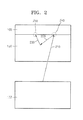
- FIG. 2 is a diagram illustrating determining a value of reference light quantity as a highly reliable value by a scanning apparatus according to an embodiment of the present invention.
- FIG. 3 is a diagram illustrating the patch 160 according to an embodiment of the present invention.
- FIG. 4 is a diagram illustrating the patch 160 according to another embodiment of the present invention.
- FIG. 5 is diagram illustrating the patch 160 according to another embodiment of the present invention.
- the light source 172 irradiates light onto a point 240 on the surface of the patch 160 in the direction 210, a portion of the light incident to the point 240 is reflected in the direction 220, a portion of the reflected light is reflected in the direction 230 when transmitting through the glass plate 150, and the reflected portion of the light is incident to another point 250 of the surface of the patch 160.
- the reference light quantity determining unit 180 determines the reference light quantity representing a reference color of the point 250 based on the quantity of light reflected in the point 250.
- the light reflected in the point 250 is not included in the light irradiated onto the point 250 but is included in the light incident in the point 250 that is reflected in the glass plate 150 as illustrated or is reflected in the light source 172 as not illustrated in the light reflected in the point 240. This is applied to the both points 240 and 250 that are all white.
- the patch 160 of the present embodiment does not overlap previously established reference colors but displays each of the previously established reference colors in a plurality of regions that are spaced apart from each other.
- the surface of the patch 160 is divided by a plurality of grids each representing one of the previously established reference colors as illustrated in FIGS. 3A and 4A .
- Each grid may be adjacent to another grid having a different color.
- the surface of the patch 160 is not realized as an image of a single white region and a single black region like a conventional patch but as an image of a plurality of white regions and a plurality of black regions that are spaced apart from each other as illustrated in FIGS. 3A through 5A .
- a possibility that the two points 240 and 250 are white is reduced compared to a conventional possibility.
- the scanning apparatus of the present embodiment irradiates light onto each point of the surface of the patch 160 that does not overlap previously established reference colors but displays each of the previously established reference colors in a plurality of regions that are spaced apart from each other (for example, the patch 160 that displays an image of the a plurality of white regions and a plurality of black regions that are spaced apart from each other).
- the sensor (not illustrated) detects light reflected in each point.
- the reference light quantity determining unit 180 determines each value of reference light quantities representing reference colors (white and black) based on quantities of lights detected by the sensor (not illustrated), thereby determining highly reliable reference light quantities.
- the patch 160 will be described in more detail with reference to FIGS. 3A-3E .
- FIG. 3A illustrates an image displayed on the patch 160 of an embodiment of the present invention.
- the image includes a 3-1 image 310 and a 3-2 image 320.
- the scanning unit 170 separately scans the 3-1 image 310 and the 3-2 image 320.
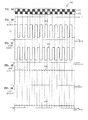
- FIG. 3B illustrates the quantity of light detected by the sensor (not illustrated).
- a vertical axis represents the quantity of light reflected from the 3-1 image 310.
- An X axis represents a waveform 312 that is a location of the light reflected from the 3-1 image 310.
- FIG. 3C illustrates the quantity of light detected by the sensor (not illustrated).
- a vertical axis represents the quantity of light reflected from the 3-2 image 320.
- An X axis represents a waveform 322 that is a location of the light reflected from the 3-2 image 320.
- the quantity of light detected by the sensor (not illustrated) alternatively includes relatively high regions and relatively low regions.
- the quantity of light detected by the sensor (not illustrated) having relatively high regions is quantity of light reflected in a white region.
- the quantity of light detected by the sensor (not illustrated) having relatively low regions represents quantity of light reflected in a black region.
- the quantities of light reflected in a white region differs according to whether the light is reflected in a portion (for example, a center portion) other than a boundary of the white region or the light is reflected in a boundary of the white region.
- the quantities of light reflected in a black region differ according to whether the light is reflected in a portion (for example, a center portion) other than a boundary of the black region or the light is reflected in a boundary of the black region.
- the waveforms 312 and 322 cannot be rectangular pulse waveforms since the light reflected in the patch 160 is somewhat diffracted and reaches the sensor (not illustrated), and is incident to the sensor (not illustrated), passes through a lens of the sensor (not illustrated), and somewhat spreads.
- a waveform 330 represents the quantity of light that is not the smaller of the quantity of light illustrated in FIG. 3B and the quantity of light illustrated in FIG. 3C in each of locations on an X axis.
- the waveform 330 represents quantity of light reflected in a white region of the patch 160 in a vertical axis, and a location of the light reflected in the white region of the patch 160 in the X axis.
- a waveform 340 represents the quantity of light that is not the bigger of the quantity of light illustrated in FIG. 3B and the quantity of light illustrated in FIG. 3C in each location on an X axis.
- the waveform 340 represents the quantity of light reflected in a black region of the patch 160 in a vertical axis, and a location of the light reflected in the black region of the patch 160 in the X axis.
- the patch 160 of an embodiment of the present invention will be described in more detail with reference to FIGS. 4A-4F .
- FIG. 4A illustrates another example of the image displayed on the patch 160 of an embodiment of the present invention.
- the patch 160 includes the previously established reference colors (for example, white and black) in a plurality of regions that are spaced apart from each other.
- the plurality of regions may have the same color as that of a region including the boundary and include a region excluding the boundary at a location.
- the image displayed on the surface of the patch 160 illustrated in FIG. 4A includes a 4-1 image 410, a 4-2 image 420, and a 4-3 image 430.
- the scanning unit 170 separately scans the 4-1 image 410, the 4-2 image 420, and the 4-3 image 430.
- FIG. 4B illustrates quantity of light detected by the sensor (not illustrated).
- a vertical axis represents the quantity of light reflected from the 4-1 image 410.
- An X axis represents a waveform 412 that is a location of the light reflected from the 4-1 image 410.
- FIG. 4C illustrates the quantity of light detected by the sensor (not illustrated).
- a vertical axis represents the quantity of light reflected from the 4-2 image 420.
- An X axis represents a waveform 422 that is a location of the light reflected from the 4-2 image 420.
- FIG. 4D illustrates the quantity of light detected by the sensor (not illustrated).
- a vertical axis represents the quantity of light reflected from the 4-3 image 430.
- An X axis represents a waveform 432 that is a location of the light reflected from the 4-3 image 430.
- the quantity of light detected by the sensor alternatively includes relatively high regions and relatively low regions.
- the quantity of light detected by the sensor (not illustrated), having relatively high regions is the quantity of light reflected in a white region.
- the quantity of light detected by the sensor (not illustrated), having relatively low regions represents the quantity of light reflected in a black region.
- quantities of light reflected in a white region differs according to whether the light is reflected in a portion (for example, a center portion) other than the boundary of the white region or the light is reflected in the boundary of the white region.
- quantities of light reflected in a black region differ according to whether the light is reflected in a portion (for example, a center portion) other than the boundary of the black region or the light is reflected in the boundary of the black region.
- the waveforms 412, 422, and 432 cannot be rectangular pulse waveforms since the light reflected in the patch 160 is somewhat diffracted and reaches the sensor (not illustrated),is incident to the sensor (not illustrated), passes through a lens of the sensor (not illustrated), and somewhat spreads.
- corners of pulse waveforms are referred to as curve portions, and the other portions are referred to as non-curve portions.
- a waveform 440 represents a largest quantity of light among the quantities of lights illustrated in FIGS. 4B through 4D in each location on an X axis.
- the waveform 440 represents the quantity of light reflected in a white region of the patch 160 in a vertical axis, and a location of the light reflected in the white region of the patch 160 in the X axis.
- a waveform 450 represents a smallest quantity of light among the quantities of lights illustrated in FIGS. 4B through 4D in each location on an X axis.
- the waveform 450 represents the quantity of light reflected in a black region of the patch 160 in a vertical axis, and a location of the light reflected in the white region of the patch 160 in the X axis.
- the waveform 440 is a vertical waveform unlike the waveform 330 illustrated in FIG. 3D .
- the sensor detects the quantity of light 424 of non-curve portions at a location on the X axis where the quantity of light 414 of curve portions is detected by the sensor (not illustrated).
- the waveform 450 is a vertical waveform unlike the waveform 340 illustrated in FIG. 3E .
- the sensor detects the quantity of light 434 of non-curve portions at a location on the X axis where the quantity of light 426 of curve portions is detected by the sensor (not illustrated).
- the determined reference light quantity can be always reliable.
- the patch 160 of an embodiment of the present invention will be described in more detail with reference to FIGS. 5A-5H .
- FIG. 5A illustrates another example of the image displayed on the patch 160 of an embodiment of the present invention.
- the patch 160 is a generalized type of the patch 160 illustrated in FIG. 4A .
- Each of reference colors (for example, white and black) may be expressed in slant type regions of the patch 160.
- the scanning unit 170 (FIG. 10) scans an image corresponding to each location on a Y axis in the image displayed in the patch 160, thereby scanning an entire image displayed on the patch 160.
- Each of images 510 through 550 corresponds to a location on the Y axis among the images displayed on the patch 160.
- FIG. 5B illustrates the quantity of light detected by the sensor (not illustrated).
- a vertical axis represents the quantity of light reflected from the image 510.
- An X axis represents a waveform 512 that is a location of the light reflected from the image 510.
- FIG. 5C illustrates the quantity of light detected by the sensor (not illustrated).
- a vertical axis represents the quantity of light reflected from the image 520.
- An X axis represents a waveform 522 that is a location of the light reflected from the image 520.
- FIG. 5D illustrates the quantity of light detected by the sensor (not illustrated).
- a vertical axis represents the quantity of light reflected from the image 530.
- An X axis represents a waveform 532 that is a location of the light reflected from the image 530.
- FIG. 5E illustrates the quantity of light detected by the sensor (not illustrated).
- a vertical axis represents the quantity of light reflected from the image 540.
- An X axis represents a waveform 542 that is a location of the light reflected from the image 540.
- FIG. 5F illustrates the quantity of light detected by the sensor (not illustrated).
- a vertical axis represents the quantity of light reflected from the image 550.
- An X axis represents a waveform 552 that is a location of the light reflected from the image 550. Meanwhile, referring to FIGS.
- the quantity of light detected by the sensor (not illustrated) alternatively includes relatively high regions and relatively low regions.
- the quantity of light detected by the sensor (not illustrated), having relatively high regions, is the quantity of light reflected in a white region.
- the quantity of light detected by the sensor (not illustrated), having relatively low regions, represents the quantity of light reflected in a black region.
- the quantities of light reflected in a white region differs according to whether the light is reflected in a portion (for example, a center portion) other than the boundary of the white region or the light is reflected in the boundary of the white region.
- the quantities of light reflected in a black region differ according to whether the light is reflected in a portion (for example, a center portion) other than the boundary of the black region or the light is reflected in the boundary of the black region.
- the waveforms 512 through 552 cannot be rectangular pulse waveforms since the light reflected in the patch 160 is somewhat diffracted and reaches the sensor (not illustrated), is incident to the sensor (not illustrated), passes through a lens of the sensor (not illustrated), and somewhat spreads.
- corners of pulse waveforms are referred to as curve portions, and the other portions are referred to as non-curve portions.
- a waveform 560 represents a largest quantity of light among the quantities of lights illustrated in FIGS. 5B through 5F in each of locations on an X axis.
- the waveform 560 represents the quantity of light reflected in a white region of the patch 160 in a vertical axis, and a location of the light reflected in the white region of the patch 160 in the X axis.
- a waveform 570 represents a smallest quantity of light among the quantities of lights illustrated in FIGS. 5B through 5F in each location on an X axis.
- the waveform 570 represents the quantity of light reflected in a black region of the patch 160 in a vertical axis, and a location of the light reflected in the white region of the patch 160 in the X axis.
- the waveform 560 is a vertical waveform unlike the waveform 330 illustrated in FIG. 3D .
- the sensor detects the quantity of light 524 of non-curve portions at a location on the X axis where the quantity of light 514 of curve portions is detected by the sensor (not illustrated).
- the waveform 570 is a vertical waveform unlike the waveform 340 illustrated in FIG. 3E .
- the sensor detects the quantity of light 544 of non-curve portions at a location on the X axis where the quantity of light 534 of curve portions is detected by the sensor (not illustrated).
- the determined reference light quantity can be always reliable.
- a unit patch is a basic unit that constitutes an entire region of the patch 160.
- the unit patch may be rectangular.
- the area of the unit patch may be a previously established value.
- the grid illustrated in FIG. 3A may be an example of the unit patch.
- Each of a first patch row through an N th patch row (N is a natural number) are unit patches arranged in one or more locations on the Y axis among the unit patches constituting the patch 160. Locations on the X axis are various unit patches.
- the 3-1 image 310 and the 3-2 image 320 illustrated in FIG. 3A are examples of a first patch row and a second patch row.
- FIG. 6 is a flowchart illustrating a reference light quantity determining method according to an embodiment of the present invention. The method will be described with reference to FIGS. 1A through 1 D .
- the scanning unit 170 scans the patch 160 that does not overlap previously established reference colors but displays each of the previously established reference colors in a plurality of regions that are spaced apart from each other (Operation 610).
- the reference light quantity determining unit 180 determines the reference light quantity representing each of the previously established reference colors based on the scanning result (Operation 620).
- the present invention can also be embodied as computer-readable codes on a computer-readable medium.
- the computer-readable medium can include a computer-readable recording medium and a computer-readable transmission medium.
- the computer-readable recording medium is any data storage device that can store data that can be thereafter read by a computer system. Examples of the computer-readable recording medium include read-only memory (ROM), random-access memory (RAM), CD-ROMs, magnetic tapes, floppy disks, and optical data storage devices.
- the computer-readable recording medium can also be distributed over network coupled computer systems so that the computer-readable code is stored and executed in a distributed fashion.
- the computer-readable transmission medium can transmit carrier waves or signals (e.g., wired or wireless data transmission through the Internet). Also, functional programs, codes, and code segments to accomplish the present invention can be easily construed by programmers skilled in the art to which the present invention pertains.
- the scanning apparatus and the reference light quantity determining method irradiate light on each point on the surface of a patch that does not overlap previously established reference colors but displays each of the previously established reference colors in a plurality of regions that are spaced apart from each other, detect light reflected in each point, and determine reference light quantities based on the detected quantities of lights, thereby determining highly reliable reference light quantities.
Landscapes
- Engineering & Computer Science (AREA)
- Physics & Mathematics (AREA)
- Multimedia (AREA)
- General Physics & Mathematics (AREA)
- Signal Processing (AREA)
- Theoretical Computer Science (AREA)
- Optics & Photonics (AREA)
- Control Or Security For Electrophotography (AREA)
- Spectrometry And Color Measurement (AREA)
- Image Input (AREA)
- Mechanical Optical Scanning Systems (AREA)
Applications Claiming Priority (1)
| Application Number | Priority Date | Filing Date | Title |
|---|---|---|---|
| KR1020070079139A KR101158006B1 (ko) | 2007-08-07 | 2007-08-07 | 스캐닝 장치 및 이를 위한 기준광량 결정방법 |
Publications (2)
| Publication Number | Publication Date |
|---|---|
| EP2023597A2 true EP2023597A2 (de) | 2009-02-11 |
| EP2023597A3 EP2023597A3 (de) | 2012-01-04 |
Family
ID=39674827
Family Applications (1)
| Application Number | Title | Priority Date | Filing Date |
|---|---|---|---|
| EP08160734A Ceased EP2023597A3 (de) | 2007-08-07 | 2008-07-18 | Abtastvorrichtung und Verfahren zur Bestimmung der Referenzlichtmenge dafür |
Country Status (4)
| Country | Link |
|---|---|
| US (1) | US8253999B2 (de) |
| EP (1) | EP2023597A3 (de) |
| KR (1) | KR101158006B1 (de) |
| CN (1) | CN101365036B (de) |
Families Citing this family (2)
| Publication number | Priority date | Publication date | Assignee | Title |
|---|---|---|---|---|
| JP2018182614A (ja) * | 2017-04-18 | 2018-11-15 | 株式会社リコー | 画像読取装置、圧板開閉検知方法、及び画像形成装置 |
| CN109687914B (zh) * | 2018-12-25 | 2021-07-13 | 重庆蓝岸通讯技术有限公司 | 无线信号识别区域光源指示机构 |
Citations (2)
| Publication number | Priority date | Publication date | Assignee | Title |
|---|---|---|---|---|
| EP1365576A2 (de) * | 2002-05-22 | 2003-11-26 | Creo IL. Ltd. | Verfahren und Apparat zur Kalibrierung der Punktvergrösserung |
| EP1574345A2 (de) * | 2004-02-20 | 2005-09-14 | Ricoh Company | Verfahren zum Erfassen einer Positionsabweichung und Bilderzeugungsvorrichtung |
Family Cites Families (22)
| Publication number | Priority date | Publication date | Assignee | Title |
|---|---|---|---|---|
| GB580176A (en) * | 1943-05-06 | 1946-08-29 | Arnold Tustin | Improvements in and relating to vibration damping devices |
| EP0295491B1 (de) * | 1987-06-04 | 1993-08-18 | Dainippon Screen Mfg. Co., Ltd. | Gerät und Verfahren zur Stabilisierung der Lichtmenge einer Fluoreszenzlampe |
| JPH04250479A (ja) * | 1991-01-28 | 1992-09-07 | Ricoh Co Ltd | 画像濃度制御方法 |
| US5198907A (en) * | 1991-08-23 | 1993-03-30 | Eastman Kodak Company | Method and appratus for automatically locating predefined exposure areas in a scanned image |
| US5809213A (en) * | 1996-02-23 | 1998-09-15 | Seiko Epson Corporation | Automatic color calibration of a color reproduction system |
| JP3649515B2 (ja) * | 1996-05-13 | 2005-05-18 | セイコーエプソン株式会社 | カラー画像読取方法、カラー画像読取装置およびカラー画像読取システム |
| US6404517B1 (en) * | 1998-03-31 | 2002-06-11 | Seiko Epson Corporation | Color-patch sheet registration |
| US6982813B2 (en) * | 2000-02-16 | 2006-01-03 | Minolta Co., Ltd. | Light quantity correction method for exposing device, and image forming device |
| JP2002055668A (ja) | 2000-08-10 | 2002-02-20 | Sharp Corp | 表示装置の入出力特性測定方法、表示装置の画像補正方法、表示装置のiccプロファイル作成方法およびそれらの方法の手順を記憶した記憶媒体並びに表示装置 |
| US6972867B1 (en) * | 2000-11-10 | 2005-12-06 | Xerox Corporation | Patch codes for color calibration job identification encoding |
| JP2002300402A (ja) * | 2001-03-30 | 2002-10-11 | Fuji Photo Film Co Ltd | 画像処理装置、方法及び記録媒体 |
| JP2004180013A (ja) * | 2002-11-27 | 2004-06-24 | Toshiba Tec Corp | 色変換装置および色変換方法 |
| KR100503799B1 (ko) * | 2003-07-24 | 2005-07-26 | 삼성전자주식회사 | 광 파워 제어 장치 및 방법 |
| JP4238996B2 (ja) * | 2004-03-09 | 2009-03-18 | セイコーエプソン株式会社 | 印刷方法および印刷装置 |
| JP4217643B2 (ja) * | 2004-03-18 | 2009-02-04 | キヤノン株式会社 | 画像濃度補正方法及び画像濃度補正システム |
| JP4457976B2 (ja) * | 2004-07-27 | 2010-04-28 | ブラザー工業株式会社 | 画像読取装置及び画像読取方法 |
| US7542172B2 (en) * | 2004-11-24 | 2009-06-02 | Xerox Corporation | Method of detecting pages subject to reload artifact |
| JP2007060613A (ja) * | 2005-07-29 | 2007-03-08 | Ricoh Co Ltd | 画像読取装置 |
| US7715047B2 (en) * | 2006-02-17 | 2010-05-11 | Seiko Epson Corporation | Image editing device |
| US7894109B2 (en) * | 2006-08-01 | 2011-02-22 | Xerox Corporation | System and method for characterizing spatial variance of color separation misregistration |
| US7583409B2 (en) * | 2007-02-26 | 2009-09-01 | Xerox Corporation | Patch codes with improved robustness |
| US8072648B2 (en) * | 2007-07-26 | 2011-12-06 | Xerox Corporation | Halftone independent correction of spatial non-uniformities |
-
2007
- 2007-08-07 KR KR1020070079139A patent/KR101158006B1/ko not_active Expired - Fee Related
-
2008
- 2008-06-30 CN CN2008101292957A patent/CN101365036B/zh not_active Expired - Fee Related
- 2008-07-18 EP EP08160734A patent/EP2023597A3/de not_active Ceased
- 2008-07-29 US US12/181,611 patent/US8253999B2/en not_active Expired - Fee Related
Patent Citations (2)
| Publication number | Priority date | Publication date | Assignee | Title |
|---|---|---|---|---|
| EP1365576A2 (de) * | 2002-05-22 | 2003-11-26 | Creo IL. Ltd. | Verfahren und Apparat zur Kalibrierung der Punktvergrösserung |
| EP1574345A2 (de) * | 2004-02-20 | 2005-09-14 | Ricoh Company | Verfahren zum Erfassen einer Positionsabweichung und Bilderzeugungsvorrichtung |
Also Published As
| Publication number | Publication date |
|---|---|
| KR101158006B1 (ko) | 2012-06-25 |
| CN101365036A (zh) | 2009-02-11 |
| EP2023597A3 (de) | 2012-01-04 |
| US20090040575A1 (en) | 2009-02-12 |
| CN101365036B (zh) | 2013-07-17 |
| US8253999B2 (en) | 2012-08-28 |
| KR20090014845A (ko) | 2009-02-11 |
Similar Documents
| Publication | Publication Date | Title |
|---|---|---|
| US7768676B2 (en) | Image reading apparatus | |
| EP1132852B1 (de) | Optische Koordinaten-Eingabe/Detektionsvorrichtung mit Korrekturfunktion von Positionierfehlern der optischen Einheit | |
| US20150256715A1 (en) | Image processing apparatus and image processing method | |
| KR20120123849A (ko) | 선택적인 픽셀 비닝 장치 및 방법 | |
| EP2023597A2 (de) | Abtastvorrichtung und Verfahren zur Bestimmung der Referenzlichtmenge dafür | |
| US6198088B1 (en) | Methods and apparatus for detecting a document on a platen | |
| US7400430B2 (en) | Detecting and compensating for color misregistration produced by a color scanner | |
| US20190149701A1 (en) | Reading apparatus, image processing program, and image production method | |
| CN101197912A (zh) | 图像处理设备和图像处理方法 | |
| CN106940630A (zh) | 移动信息处理装置、图像输出、读取装置、系统和方法 | |
| US11321038B2 (en) | Display control device and non-transitory computer readable medium storing display control program for setting display time according to display priority | |
| US8599401B2 (en) | Image processing device, image processing system, and computer readable medium | |
| US10142505B2 (en) | Multi-function printer | |
| EP2552092B1 (de) | Bildabtastvorrichtung mit Funktion zur Detektion von Kondensation | |
| KR20080006112A (ko) | 경계 영역의 선명도를 개선하는 하프토닝 방법 및 장치 | |
| US10212299B2 (en) | Detecting a folded page in a digital image of a scanned document | |
| US7253427B2 (en) | Automatic object plane detection system and method | |
| US10404881B2 (en) | Light source unit, image processing apparatus, image processing system and image processing method | |
| US11523031B2 (en) | Image processing apparatus, control method of image processing apparatus, and storage medium | |
| JP6895271B2 (ja) | 画像処理装置及び画像処理方法 | |
| TW201921283A (zh) | 二維碼及二維碼讀取裝置 | |
| CN101388944A (zh) | 图像读取设备与使用该设备校正图像的方法 | |
| JP6488182B2 (ja) | 画像処理装置、画像形成装置および画像処理方法 | |
| JP2000276564A (ja) | 2次元コード | |
| JP7347027B2 (ja) | 画像処理装置及び画像処理プログラム |
Legal Events
| Date | Code | Title | Description |
|---|---|---|---|
| PUAI | Public reference made under article 153(3) epc to a published international application that has entered the european phase |
Free format text: ORIGINAL CODE: 0009012 |
|
| AK | Designated contracting states |
Kind code of ref document: A2 Designated state(s): AT BE BG CH CY CZ DE DK EE ES FI FR GB GR HR HU IE IS IT LI LT LU LV MC MT NL NO PL PT RO SE SI SK TR |
|
| AX | Request for extension of the european patent |
Extension state: AL BA MK RS |
|
| PUAL | Search report despatched |
Free format text: ORIGINAL CODE: 0009013 |
|
| AK | Designated contracting states |
Kind code of ref document: A3 Designated state(s): AT BE BG CH CY CZ DE DK EE ES FI FR GB GR HR HU IE IS IT LI LT LU LV MC MT NL NO PL PT RO SE SI SK TR |
|
| AX | Request for extension of the european patent |
Extension state: AL BA MK RS |
|
| RIC1 | Information provided on ipc code assigned before grant |
Ipc: H04N 1/407 20060101AFI20111130BHEP |
|
| 17P | Request for examination filed |
Effective date: 20120703 |
|
| AKX | Designation fees paid |
Designated state(s): DE FR GB NL |
|
| RAP1 | Party data changed (applicant data changed or rights of an application transferred) |
Owner name: SAMSUNG ELECTRONICS CO., LTD. |
|
| 17Q | First examination report despatched |
Effective date: 20130416 |
|
| STAA | Information on the status of an ep patent application or granted ep patent |
Free format text: STATUS: THE APPLICATION HAS BEEN REFUSED |
|
| 18R | Application refused |
Effective date: 20150914 |