EP2023657A2 - Lautsprecher und Lautsprechervorrichtung - Google Patents
Lautsprecher und Lautsprechervorrichtung Download PDFInfo
- Publication number
- EP2023657A2 EP2023657A2 EP08012129A EP08012129A EP2023657A2 EP 2023657 A2 EP2023657 A2 EP 2023657A2 EP 08012129 A EP08012129 A EP 08012129A EP 08012129 A EP08012129 A EP 08012129A EP 2023657 A2 EP2023657 A2 EP 2023657A2
- Authority
- EP
- European Patent Office
- Prior art keywords
- bobbin
- magnetic
- coil
- control coil
- speaker
- Prior art date
- Legal status (The legal status is an assumption and is not a legal conclusion. Google has not performed a legal analysis and makes no representation as to the accuracy of the status listed.)
- Withdrawn
Links
Images


Classifications
-
- H—ELECTRICITY
- H04—ELECTRIC COMMUNICATION TECHNIQUE
- H04R—LOUDSPEAKERS, MICROPHONES, GRAMOPHONE PICK-UPS OR LIKE ACOUSTIC ELECTROMECHANICAL TRANSDUCERS; ELECTRIC HEARING AIDS; PUBLIC ADDRESS SYSTEMS
- H04R9/00—Transducers of moving-coil, moving-strip, or moving-wire type
- H04R9/02—Details
- H04R9/025—Magnetic circuit
-
- H—ELECTRICITY
- H04—ELECTRIC COMMUNICATION TECHNIQUE
- H04R—LOUDSPEAKERS, MICROPHONES, GRAMOPHONE PICK-UPS OR LIKE ACOUSTIC ELECTROMECHANICAL TRANSDUCERS; ELECTRIC HEARING AIDS; PUBLIC ADDRESS SYSTEMS
- H04R3/00—Circuits for transducers
- H04R3/002—Damping circuit arrangements for transducers, e.g. motional feedback circuits
-
- H—ELECTRICITY
- H04—ELECTRIC COMMUNICATION TECHNIQUE
- H04R—LOUDSPEAKERS, MICROPHONES, GRAMOPHONE PICK-UPS OR LIKE ACOUSTIC ELECTROMECHANICAL TRANSDUCERS; ELECTRIC HEARING AIDS; PUBLIC ADDRESS SYSTEMS
- H04R9/00—Transducers of moving-coil, moving-strip, or moving-wire type
- H04R9/06—Loudspeakers
-
- H—ELECTRICITY
- H04—ELECTRIC COMMUNICATION TECHNIQUE
- H04R—LOUDSPEAKERS, MICROPHONES, GRAMOPHONE PICK-UPS OR LIKE ACOUSTIC ELECTROMECHANICAL TRANSDUCERS; ELECTRIC HEARING AIDS; PUBLIC ADDRESS SYSTEMS
- H04R2209/00—Details of transducers of the moving-coil, moving-strip, or moving-wire type covered by H04R9/00 but not provided for in any of its subgroups
- H04R2209/041—Voice coil arrangements comprising more than one voice coil unit on the same bobbin
-
- H—ELECTRICITY
- H04—ELECTRIC COMMUNICATION TECHNIQUE
- H04R—LOUDSPEAKERS, MICROPHONES, GRAMOPHONE PICK-UPS OR LIKE ACOUSTIC ELECTROMECHANICAL TRANSDUCERS; ELECTRIC HEARING AIDS; PUBLIC ADDRESS SYSTEMS
- H04R9/00—Transducers of moving-coil, moving-strip, or moving-wire type
- H04R9/02—Details
- H04R9/025—Magnetic circuit
- H04R9/027—Air gaps using a magnetic fluid
Definitions
- the present invention relates to a speaker and a speaker apparatus.
- Electrodynamic, electrostatic, piezoelectric, electromagnetic and other types of speakers are conventionally known. Electrodynamic speakers (dynamic speakers), which are classified into a moving-coil type, a ribbon type, a Blatthaller type, a Heil type, etc. in terms of the construction of diaphragm and vibration source, are mainstream speakers since they are basically designed to drive a diaphragm by an electromagnetic force and achieve a high conversion efficiency with a relatively simple construction. A large majority of electrodynamic speakers are of moving-coil type such as a cone speaker and a dome speaker.
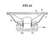
- the cone speaker includes a conical diaphragm (cone diaphragm C), a voice coil Vc and a magnetic circuit Mc that generate an electromagnetic force for driving the cone diaphragm C, a damper D that holds the voice coil Vc at a constant position relative to a gap Gp in the magnetic circuit Mc, an edge E that supports the periphery of the cone diaphragm C coupled to a tip end of the voice coil Vc, and a frame F that couples the above component parts into one piece.
- a conical diaphragm cone diaphragm C
- Vc voice coil
- Mc magnetic circuit Mc that generate an electromagnetic force for driving the cone diaphragm C
- a damper D that holds the voice coil Vc at a constant position relative to a gap Gp in the magnetic circuit Mc
- an edge E that supports the periphery of the cone diaphragm C coupled to a tip end of the voice coil Vc
- a frame F that couples the above component parts into one piece.
- an electric current is caused to flow through the voice coil Vc disposed in the gap of the magnetic circuit Mc in accordance with an audio waveform, whereby the voice coil Vc directly coupled to the cone diaphragm C is reciprocated in a direction perpendicular to the line of magnetic force.
- the damper D and the edge E serve to hold the voice coil Vc at the center of vibration.
- the vibration of diaphragm C largely depends on the mechanical characteristic of the mechanical spring construction.
- a frequency-dependent variation is caused in sound emission, posing a problem.
- Another problem is that there is a limit in increasing the amplitude of vibration of diaphragm C.
- Still another technical art disclosed in Japanese Laid-open Patent Publication No. 11-164394 includes a braking coil for exerting a braking force on the voice coils, the braking coil being disposed outside magnetic fields when the voice coils are each at a stationary position.
- the vibration reference position is adjusted by a conventional mechanical structure.
- an audio signal is supplied to the coils for being held in the vibration center position.
- these coils are deviated from a magnetic gap region, posing a problem that the efficiency of utilizing the magnetic field is lowered.
- Other problems are that the coils must be applied with biases which are opposite in polarity, resulting in a complicated driving circuit, and these coils are difficult to be utilized for any purpose (such as a motion feedback sensor) other than intended one.
- the present invention provides a speaker capable of properly adjusting a spring characteristic with which a voice coil is driven and capable of being driven in large amplitude, and provides a speaker apparatus.
- a speaker comprising a cylindrical bobbin, a support structure adapted to support the bobbin for sliding motion in an axial direction of the bobbin, a magnetic path formation frame having a magnet and a magnetic path formation member that cooperates with the magnet to form a cylindrical magnetic gap, the bobbin being disposed coaxially with the magnetic gap, and a magnetic field that passes through interior and exterior of the bobbin being formed in the magnetic gap, a control coil wound around the bobbin, and first and second coils wound around one end side and another end side of the bobbin, respectively, with the control coil disposed between the first and second coils, wherein the magnetic field is formed to be opposite in direction between the one end side and the other end side of the control coil, and the magnetic field is formed such that when a constant electric current flows through the control coil, a Lorentz force acts on the control coil in a direction of forcing back the bobbin slidingly moved from a predetermined position.
- the control coil can be disposed between magnetic gaps or disposed so as to overlap at both ends thereof the magnetic gaps in which the magnetic field is formed in opposite directions.
- a speaker apparatus comprising the speaker according to the first aspect of this invention, and a circuit adapted to supply the control coil of the speaker with a constant electric current.
- the speaker apparatus can include an output unit adapted to amplify an electric current supplied thereto and supply the first and second coils with the amplified electric current in opposite directions.
- the spring characteristic with which a voice coil including the bobbin and the like is driven can properly be adjusted and a large amplitude driving can be realized.
- FIG. 1 is a section view of a speaker according to one embodiment of this invention.
- FIG. 2 is a circuit diagram showing a current supply circuit for the speaker
- FIG. 3 is an enlarged view showing magnetic gaps
- FIG. 4 is a sectional view showing the speaker in a state where a voice coil is displaced from a stationary position
- FIG. 5 is an enlarged view showing the magnetic gaps in a state the voice coil is displaced
- FIG. 6 is a graph of an electric current supplied to front and rear coils
- FIG. 7 is a diagram showing one form of direct current supply according to a first modification of the embodiment.
- FIG. 8 is a diagram showing another form of direct current supply in the first modification
- FIG. 9 is a section view showing a speaker according to one form of a second modification of the embodiment.
- FIG. 10 is a section view showing a speaker according to another form of the second modification.
- FIG. 11 is an enlarged view showing magnetic gaps in the speaker shown in FIG. 10 ;
- FIG. 12 is a section view showing a speaker according to still another form of the second modification.
- FIG. 13 is an enlarged view showing magnetic gaps in the speaker shown in FIG. 12 ;
- FIG. 14 is a section view showing a speaker according to one form of a third modification of the embodiment, which is provided with a support structure in which magnetic fluid is used;
- FIG. 15 is a section view showing a speaker according to another form of the third modification, which is provided with a support structure in which bearings are used;
- FIG. 16 is a view showing the construction of a conventional moving coil type speaker.
- FIG. 1 shows the entire construction of a speaker 1 of one embodiment of this invention in a state that a voice coil 3 is at a stationary position (neutral or reference position).
- the speaker 1 includes a yoke 2 (housing) and a voice coil 3 disposed for sliding motion relative to the yoke 2 while remaining in contact with the yoke 2.
- the yoke 2 is comprised of an internal yoke 10 and an external yoke 11.
- the external yoke 11 is formed by a magnetic material such as iron and into a cylindrical shape having a bottom surface 11a thereof disposed on a rear side (left side in FIG. 1 ) of the speaker 1.
- the internal yoke 10 has a substantially cylindrical structure and includes a holding part 12 fixed to the bottom surface 11a of the external yoke 11, a rear plate 13 adjacent to the holding part 12, a magnet 14 adjacent to the rear plate 13, and a front plate 15 adjacent to the magnet 14.
- the magnet 14 is formed by a permanent magnet whose magnetization is maintained without an external magnetic field.
- the magnet 14 is magnetized into an N pole and an S pole on the front and rear sides thereof (right and left sides in FIG. 1 ) .
- the front and rear plates 15, 13 are each formed by a paramagnetic material that is magnetized by the magnet 14 in a direction of a magnetic field of the magnet 14, when placed in the magnetic field.
- Substantially cylindrical air gaps are formed between the external yoke 11 and the front plate 15 and between the external yoke 11 and the rear plate 13.
- the magnetic field of the magnet 14 is formed by magnetic flux produced from the magnet 14 and concentrated into the air gaps.
- the air gaps are referred to as the magnetic gaps.
- the magnetic field in the magnetic gap formed circumferentially of the front plate 15 is directed from the front plate 15 to the external yoke 11
- the magnetic field in the magnetic gap formed circumferentially of the rear plate 13 is directed from the external yoke 11 to the rear plate 13 (see FIG. 3 ).
- Sliding parts 16 which are triangle in cross section are formed on an inner peripheral surface of the external yoke 11 so as to protrude toward the internal yoke 10, the sliding parts 16 being disposed at predetermined intervals circumferentially of the inner peripheral surface of the external yoke 11. In other words, the sliding parts 16 are disposed radially as viewed from the axis of the external yoke 11.
- the voice coil 3 includes a bobbin 21, a diaphragm 22, and coils 23 to 25.
- the bobbin 21 is formed into a cylindrical shape and disposed coaxially with the cylindrical air gaps between the external yoke 11 and the front and rear plates 15, 13.
- the bobbin 21 is fitted into the gap between the external yoke 11 and the internal yoke 10 and supported by the sliding parts 16 so as to be movable in the axial direction of the bobbin 21.
- the outer peripheral surface of the bobbin 21 is smoothened (for example, plated) in a region where the bobbin 21 is in contact with the protrusion structure of the sliding parts 16.
- the diaphragm 22 is a cone diaphragm and fixed to the front end of the cylindrical bobbin 21.
- the diaphragm 22 is formed by paper comprised of wood pulp in which various fibers such as carbon fibers are mixed, or comprised of metal such as aluminum, or ceramics, or plastics such as polypropylene.
- Coils are wound around the bobbin 21 so as to be integral therewith.
- three coils i.e., the rear coil 23, the position control coil 24, and the front coil 25 are wound around the bobbin 21.
- the front coil 25 is wound around the bobbin 21, with its turns close to one another, in a state that front and rear ends thereof are positioned offset axially inward by predetermined lengths from front and rear ends of the front plate 15 when the voice coil 3 is at the reference position as shown in FIG. 1 .
- the rear coil 23 is wound around the bobbin 21, with its front and rear ends positioned offset axially inward by predetermined lengths from front and rear ends of the rear plate 13 and with its turns close to one another.
- the position control coil 24 is wound around the bobbin 21 with its turns close to one another, and is disposed such that it overlaps the entire region of the magnet 14 and overlaps parts of the front plate 15 and the rear plate 13 by the same length.
- the current supply circuit 4 includes an amplifier 30 having output terminals thereof from which an audio signal is supplied to the front and rear coils 25, 23. Thus, an electric current is commonly supplied to the front coil 25 and the rear coil 23.
- the current supply circuit 4 includes a DC power source 31 from which a direct current of a given magnitude is supplied to the position control coil 24.
- the DC power source 31 is implemented by current supply means such as a battery or a constant DC current circuit (for example, switching regulator) for converting commercial power into direct current.
- FIG. 3 shows in enlarged scale a region (near the magnetic gaps) surrounded by a dotted line in FIG. 1 .
- a cross section of each turn of the rear coil 23, the position control coil 24, and the front coil 25 is shown by a circle with dot or a circle with cross.
- the circles with dot showing the cross sections of the rear coil 23 indicate that an electric current is supplied from the amplifier 30 to the rear coil 23 in a direction from the rear of the drawing paper of FIG. 3 to the front thereof.
- the circles with cross showing the cross sections of the front coil 25 indicate that an electric current is supplied to the front coil 25 in a direction from the front of the drawing paper to the rear thereof. That is, the electric currents supplied to the rear and front coils 23, 25 are the same in waveform but opposite in direction.
- the position control coil 24 is supplied from the DC power source 31 with a direct current flowing from the rear of the drawing paper to the front thereof.
- FIG. 3 schematically shows the polarities (directions) of electric currents supplied to the rear coil 23, the position control coil 24, and the front coil 25, but does not accurately show the number and winding density of turns of each coil. Arrows shown across the magnetic gaps represent the directions of magnetic fields formed in the magnetic gaps.
- the direction of each of the Lorentz forces is determined based on the direction of the magnetic field in the magnetic gap concerned and the direction of electric current flowing to cross the magnetic field.
- the Lorentz force acts on the coil 24 in the rearward direction (toward the left in FIG. 1 ).
- the Lorentz force acts on the coil 24 in the forward direction.
- FIG. 4 shows the voice coil 3 slightly moved forward from the reference position
- FIG. 5 shows in enlarged scale a region (near the magnetic gaps) surrounded by a dotted line in FIG. 4 .
- the length of the position control coil 24 crossing the magnetic gap is longer at the front end portion thereof than at the rear end portion thereof. Since the Lorentz force acting on the coil is proportional to the length of the coil crossing the magnetic gap, the force acting on the front end portion of the position control coil 24 (exerting leftward in FIG. 4 ) is larger than the force acting on the rear end portion thereof (exerting rightward in FIG. 4 ). Thus, the vector sum of the Lorentz forces acts in the leftward direction, which is opposite from the moving direction of the voice coil 3.
- the voice coil 3 when the voice coil 3 is moved from the reference position either forward or rearward, the Lorentz force acts on the entire position control coil 24 in the direction opposite from the moving direction of the voice coil 3. As a result, the voice coil 3 is stably maintained at the reference position.
- the Lorentz force corresponding to the electric current flowing through the position control coil 24 and acting in the direction opposite from the moving direction of the voice coil 3 will be referred to as the "electric spring force".
- the electric spring force stably maintains the voice coil 3 at the reference position.
- an electric current of a waveform varying in dependence on the audio signal is supplied to the front and rear coils 25, 23.
- an audio signal representing a tone (pure tone) of 800 Hz is supplied in the form of a sinusoidal alternating current of 800 Hz.
- the front and rear coils 25, 23 are wound around the bobbin 21 such as to perpendicularly cross the magnetic fields in the magnetic gaps. Therefore, when an electric current is supplied to the front and rear coils 25, 23, Lorentz forces are produced due to the magnetic fields formed in the magnetic gaps. In the following, how the voice coil 3 is driven by the Lorentz forces is described.
- a direct current is supplied to the position control coil 24. Due to the supply of the direct current, a Lorentz force (electric spring force) varying depending on an amount of movement of the voice coil 3 acts in a direction opposite from the moving direction of the voice coil 3. The sum of a driving force based on an audio signal and the electric spring force acts on the entire voice coil 3 being moved. The voice coil 3 is moved to a position where the driving force based on the audio signal is balanced with the electric spring force. Thus in the current waveform section A, the voice coil 3 is moved to a position forward of the reference position.
- a Lorentz force electric spring force
- both the Lorentz forces acting on the front and rear coils 25, 23 exert in the rearward direction (leftward in FIG. 4 ), unlike in the section A.
- the electric spring force exerts in the direction (forward) opposite from the moving direction of the voice coil.
- the voice coil 3 is moved to a position rearward of the reference position.
- the actions described for the current waveform sections A, B are alternately repeated, and therefore, the voice coil 3 is reciprocated (vibrated) in accordance with the waveform of the audio signal.
- the diaphragm 22 With the vibration of the voice coil 3, the diaphragm 22 also vibrates in conjunction with the voice coil 3, whereby sound is emitted according to the waveform of the audio signal.
- the voice coil 3 when supplied with no audio signal, the voice coil 3 is stably maintained at the reference position by the electric spring force acting on the position control coil 24.
- the voice coil 3 When supplied with an audio signal, the voice coil 3 is vibrated according to the waveform of the audio signal by the driving force based on the audio signal and the electric spring force produced by the position control coil 24.
- a mechanical support member such as an edge or a spider is conventionally employed.
- problems of the voice coil vibration being limited and an undesired force being applied to the voice coil are posed due to the material or shape of the support member.
- the voice coil can be supported at the reference position for vibration and can be vibrated around the reference position at the time of sound emission without the need of using the support member, whereby the above described problems can be solved.
- the electric spring force can be controlled by changing the way of winding the position control coil 24, or controlling the direct current value, or controlling the magnetic fields in the magnetic gaps.
- the winding density of the position control coil 24 around the bobbin 21 can be adjusted as described in the following forms 1A, 1B of the first modification.
- the winding density of the position control coil 24 uniformly wound around the bobbin 21 can be increased. In that case, the electric spring force with the movement of the voice coil 3 becomes larger with increase in the winding density. If, on the other hand, the winding density is made small, the electric spring force becomes small.
- the winding density of the position control coil 24 around the bobbin 21 can be locally increased.
- the electric spring force can be controlled in various manners with the movement of the voice coil 3. For example, in a case that the winding density of the position control coil 24 is made high near the center of the winding width and made low at both end portions of the winding width, the electric spring force becomes large with increase of movement of the voice coil 3 to thereby make it difficult for the voice coil 3 to move.
- the value of the direct current supplied to the position control coil 24 can be changed, as described in the following forms 1C to 1E of the first modification.
- the direct current supplied to the position control coil 24 can be set to a value different between types of music piece or between types of acoustic space, whereby sound of acoustic characteristics suitable to circumstance can be emitted.
- a desired output value may be selected by means of switches SW1 to SWn.
- the amplifier 30 may have an additional function of outputting a control signal to instruct the DC power source 32 to change the output value in accordance with the control signal. In that case, the amplifier 30 may be provided with a selection switch by means of which the content of the control signal is changed.
- the amplifier 30 may have a function of automatically identifying a type of music piece (for example, by means of processing to identify the genre based on range detection or beat detection) or a type of acoustic space based on a result of analysis of audio signal or based on a signal from audio signal output equipment (external equipment), and in accordance with the identified type of music piece or acoustic space, the control signal may be output.
- the magnet 14 may be replaced, or the distance between the magnetic gaps or the magnitude of the magnetic gaps may be changed.
- the desired form of electric spring force can be set by the user.
- the above electric setting of the spring characteristic it is possible to realize acoustic effects which are difficult to be realized by the mechanical support member.
- the position control coil 24 is stably held at the reference position by winding the coil 24 around the voice coil 3 such that the length of the coil 24 crossing the magnetic gaps is the same between the both ends thereof.
- the way of winding the position control coil 24 and the way of supplying the direct current are not limited to those in the embodiment.
- the position control coil 24 can stably be held at the reference position by means of the following forms 2A to 2C of the second modification.
- the position control coil 24 may have a winding width extending between the rear end of the front plate 15 and the front end of the rear plate 13 so that the coil 24 overlaps neither of the magnetic gaps, as shown in FIG. 9 .
- the electric current is made to flow through the position control coil 24 in the direction from the rear of the drawing paper to the front thereof in a region surrounded by the dotted line in FIG. 9 .
- the voice coil 3 is at the reference position, the position control coil 24 crosses neither of the magnetic gaps, and therefore, the voice coil 3 is not applied with Lorentz forces.
- the front end of the position control coil 24 crosses the magnetic gap.
- two position control coils 24 may be provided (which are distinctively denoted by different numerals 24B, 24F).
- the position control coil 24F may be wound around the voice coil 3 such that both ends of the coil 24F are displaced forwardly relative to both ends of the magnetic gap formed circumferentially of the front plate 15, whereas the other position control coil 24B may be wound such that both ends thereof are displaced rearwardly relative to both ends of the magnetic gap formed circumferentially of the rear plate 13.
- the DC power source 31 may be adapted to supply the position control coil 24 with a direct current flowing therethrough in a direction from the front of the drawing paper to the rear thereof in a region A surrounded by a dotted line in FIG. 10 .
- FIG. 11 shows a positional relation between the position control coils 24B, 24F and the magnetic gaps observed when the voice coil 3 shown in FIG. 10 is moving forward. Illustrations of the front and rear coils 25, 23 are omitted in FIG. 11 .
- a forward Lorentz force acts on the position control coil 24F and a rearward Lorentz force acts on the position control coil 24B. Since the length of the position control coil 24B crossing the magnetic gap is larger than the length of the position control coil 24F crossing the other magnetic gap, the Lorentz force acting on the coil 24B is larger than the Lorentz force acting on the coil 24F. As a result, the vector sum of the Lorentz forces acting on the position control coils 24 exerts in the rearward direction (leftward in FIG. 11 ) opposite from the moving direction of the voice coil 3.
- the voice coil 3 is stably held at the reference position also in the form 2B of the second modification.
- two position control coils 24 (which are distinctively denoted by reference numerals 24b, 24f) may be provided.
- the position control coil 24f is wound around the voice coil 3 from a position offset rearward by a predetermined length from the front end of the magnetic gap formed circumferentially of the front plate 15 to a position offset rearward from the rear end of the magnetic gap.
- the position control coil 24b may be wound in symmetric with the position control coil 24f. In that case, the direct current is supplied to the position control coils 24 in the direction from the rear of the drawing paper to the front thereof in a region B surrounded by the dotted line in FIG. 12 .
- FIG. 13 shows a positional relation between the position control coils 24 and the magnetic gaps when the voice coil 3 shown in FIG. 12 is moving forward. Illustration of the front and rear coils 25, 23 is omitted in FIG. 13 .
- the voice coil 3 is stably retained at the reference position.
- any of the forms 2A to 2C of the second modification when the voice coil 3 is at the reference position, no Lorentz forces act on the position control coils 24 to which an electric current is being supplied. Even if Lorentz forces act on the coils 24, the vector sum of the Lorentz forces is equal to zero.
- the voice coil 3 is slightly displaced forward or rearward from the reference position, portions of the position control coils 24 crossing the magnetic gaps formed circumferentially of the front and rear plates 15, 13 vary, and the vector sum of the Lorentz forces acting on the position control coils 24 is exerted in the direction opposite from the moving direction of the position control coils 24.
- the voice coil 3 is stably held at the reference position.
- sliding parts 16 of projection structure are provided as a support structure that supports the voice coil 3 for sliding motion inside the external yoke 11.
- the support structure is not limited to that of the embodiment.
- the following is a description of forms 3A to 3C of a third modification, in which examples of the support structure are shown.
- FIG. 14 shows in cross section a speaker 1 having a support structure in which magnetic fluid is used.
- the magnetic fluid comprises a medium solution in which fine magnetic particles having surfaces thereof processed with interfacial active agent are suspended.
- the external yoke 11 is formed at its inner peripheral surface with a recess structure 18 formed by a magnet.
- a magnetic fluid 19 poured into a recess in the recess structure 18 is held in the recess with fluidity.
- the bobbin 21 is formed by a non-magnetic material and has a smooth surface thereof.
- the bobbin 21 is fitted to the inner peripheral surface of the external yoke 11 in a state that the bobbin 21 is held at its outer peripheral surface inside the external yoke 11 via the magnetic fluid 19. That is, the voice coil 3 is held by the magnetic fluid 19 in a floating state.
- the magnetic fluid 19 is magnetically attracted by the magnet of the recess structure 18, and remains held inside the recess of the recess structure 18.
- the voice coil 3 is held inside the external yoke 11 via the magnetic fluid 19, a contact resistance produced when the voice coil 3 vibrates in the external yoke 11 can be suppressed to be small.
- the external yoke 11 and the voice coil 3 are not in direct contact with each other at the time of relative sliding motion, and therefore, wear of contact portions therebetween is not caused.
- fluidity resistance of the magnetic fluid 19 may be varied to thereby adjust the resistance between the voice coil 3 and the external yoke 11.
- characteristics of the magnetic fluid can be adjusted by varying chemical compositions of the interfacial active agent and/or the medium liquid used for production of the magnetic fluid 19.
- FIG. 15 shows in cross section a speaker 1 having a support structure in which bearings are used.
- the external yoke 11 is provided at its inner peripheral surface with conventional ball bearing structures 17.
- the outer peripheral surface of the bobbin 21 is processed to be smooth by, for example, plating, and the bobbin 21 is fitted to the bearing structures 17 disposed inside the external yoke 11, whereby the bobbin 21 is held inside the external yoke 11 via the ball bearing structures 17.
- the voice coil 3 vibrates as described in the embodiment, the voice coil 3 makes a smooth sliding motion relative to the yoke 2.
- the external yoke 11 and the voice coil 3 are disposed in indirect contact with each other via the ball bearing structures 17, whereby a problem such as wear of contact portions therebetween can be eliminated.
- a speaker according to the form 3C of the third modification is the same in construction as the conventional speaker except for the mechanical characteristic of the edge of the speaker.
- the conventional speaker includes the edge constituted by fiber, urethane foam, or other material.
- a support member of extremely low elasticity may be used.
- the support member may be thin in thickness or may be fabricated by a material of low strength. With such a support member, the spring characteristic of the support member can be prevented from largely affecting the drive of the voice coil 3.
- the amplifier 30 and the DC power source 31 are fabricated separately from the speaker 1.
- the speaker 1 and the DC power source 31 may be combined together and incorporated into a common speaker enclosure or the like.
- the DC power source 31 may be disposed in the amplifier 30. That is, a constant DC power source may be incorporated into a circuit of the amplifier 30.
- the sliding parts 16 described in the embodiment are provided on the inner peripheral surface of the external yoke 11.
- the sliding parts 16 may be provided on the outer peripheral surface of the bobbin 21.
Landscapes
- Physics & Mathematics (AREA)
- Engineering & Computer Science (AREA)
- Acoustics & Sound (AREA)
- Signal Processing (AREA)
- Audible-Bandwidth Dynamoelectric Transducers Other Than Pickups (AREA)
- Circuit For Audible Band Transducer (AREA)
Applications Claiming Priority (1)
| Application Number | Priority Date | Filing Date | Title |
|---|---|---|---|
| JP2007194266A JP5332146B2 (ja) | 2007-07-26 | 2007-07-26 | スピーカ装置 |
Publications (2)
| Publication Number | Publication Date |
|---|---|
| EP2023657A2 true EP2023657A2 (de) | 2009-02-11 |
| EP2023657A3 EP2023657A3 (de) | 2013-06-26 |
Family
ID=39884211
Family Applications (1)
| Application Number | Title | Priority Date | Filing Date |
|---|---|---|---|
| EP08012129.6A Withdrawn EP2023657A3 (de) | 2007-07-26 | 2008-07-04 | Lautsprecher und Lautsprechervorrichtung |
Country Status (4)
| Country | Link |
|---|---|
| US (1) | US8073187B2 (de) |
| EP (1) | EP2023657A3 (de) |
| JP (1) | JP5332146B2 (de) |
| CN (1) | CN101355826A (de) |
Cited By (5)
| Publication number | Priority date | Publication date | Assignee | Title |
|---|---|---|---|---|
| WO2010097568A1 (en) * | 2009-02-24 | 2010-09-02 | Armour Home Electronics Ltd | Improvements to loudspeakers |
| US9800980B2 (en) | 2015-09-14 | 2017-10-24 | Wing Acoustics Limited | Hinge systems for audio transducers and audio transducers or devices incorporating the same |
| US11137803B2 (en) | 2017-03-22 | 2021-10-05 | Wing Acoustics Limited | Slim electronic devices and audio transducers incorporated therein |
| US11166100B2 (en) | 2017-03-15 | 2021-11-02 | Wing Acoustics Limited | Bass optimization for audio systems and devices |
| WO2021247986A3 (en) * | 2020-06-04 | 2022-05-05 | Clean Energy Labs, Llc | Voice coil actuator and loudspeakers containing same |
Families Citing this family (16)
| Publication number | Priority date | Publication date | Assignee | Title |
|---|---|---|---|---|
| HU229608B1 (en) * | 2011-10-04 | 2014-03-28 | Zoltan Bay | Loudspeaker |
| FR3006847B1 (fr) * | 2013-06-10 | 2017-02-10 | Devialet | Chaine de conversion electroacoustique a bobine alimentee selectivement |
| CN103763665B (zh) * | 2014-01-04 | 2021-07-27 | 头领科技(昆山)有限公司 | 一种平板扬声器振膜及具有该振膜的耳机扬声器 |
| US10194249B2 (en) | 2017-06-14 | 2019-01-29 | Apple Inc. | Multi-coil loudspeaker driver |
| US20200213785A1 (en) * | 2017-08-08 | 2020-07-02 | Panasonic Intellectual Property Management Co., Ltd. | Loudspeaker and acoustic device |
| US20200374613A1 (en) * | 2017-08-08 | 2020-11-26 | Panasonic Intellectual Property Management Co., Ltd. | Loudspeaker and earphones |
| CN109842841B (zh) * | 2017-11-27 | 2024-04-02 | 深圳市三诺数字科技有限公司 | 一种扬声器装置 |
| WO2020033892A1 (en) * | 2018-08-09 | 2020-02-13 | Fallon James J | Sound production using speaker enclosure with reduced internal pressure |
| WO2020207608A1 (en) | 2019-04-11 | 2020-10-15 | Mayht Holding B.V. | Linear motor magnet assembly and loudspeaker unit |
| CN111866675B (zh) * | 2019-04-30 | 2022-08-19 | 歌尔股份有限公司 | 一种扬声器单体、扬声器模组及电子设备 |
| US11102575B1 (en) * | 2020-02-05 | 2021-08-24 | Tymphany Acoustic Technology Limited | Loudspeaker with passively controlled voice coil sections |
| KR102723668B1 (ko) * | 2020-04-09 | 2024-10-30 | 현대자동차주식회사 | 진동스피커 |
| FR3129054B1 (fr) * | 2021-11-10 | 2023-10-20 | Devialet | Procédé de retenue d’une membrane d’un haut-parleur |
| CN216775009U (zh) * | 2021-12-30 | 2022-06-17 | 昆山联滔电子有限公司 | 扬声器 |
| CN115297413B (zh) * | 2022-06-28 | 2024-07-16 | 张永春 | 振动系统及扬声器 |
| US20250234136A1 (en) * | 2024-01-11 | 2025-07-17 | Afco, Inc. | Variable Impedance Speaker Apparatus |
Citations (2)
| Publication number | Priority date | Publication date | Assignee | Title |
|---|---|---|---|---|
| JPH11164394A (ja) | 1997-09-22 | 1999-06-18 | Jbl Inc | デュアル・コイル・スピーカのドライバ・ユニットにおける誘導式ブレーキング |
| JP2001186589A (ja) | 1999-12-22 | 2001-07-06 | Matsushita Electric Ind Co Ltd | スピーカユニット |
Family Cites Families (7)
| Publication number | Priority date | Publication date | Assignee | Title |
|---|---|---|---|---|
| GB2029669A (en) * | 1978-05-18 | 1980-03-19 | Lipschutz K | Moving coil transducers |
| JPS58159098A (ja) * | 1982-03-16 | 1983-09-21 | Yoshiji Yamaguchi | 電磁力ダンパ−スピ−カ− |
| JPH0632543B2 (ja) * | 1984-07-02 | 1994-04-27 | パイオニア株式会社 | スピ−カ装置 |
| US5408533A (en) * | 1993-12-13 | 1995-04-18 | Reiffin; Martin | Motional feedback speaker system with radially polarized magnet and underhung voice-coil |
| JPH08331691A (ja) * | 1995-06-05 | 1996-12-13 | Foster Electric Co Ltd | 動電型スピーカ |
| EP1293105A2 (de) * | 2001-02-13 | 2003-03-19 | Koninklijke Philips Electronics N.V. | Elektroakustischer wandler der akustisch dichter ist im luftspaltbereich der schwingspule |
| US7142685B2 (en) * | 2003-08-27 | 2006-11-28 | Dei Headquarters, Inc. | Adjustable loudspeaker |
-
2007
- 2007-07-26 JP JP2007194266A patent/JP5332146B2/ja not_active Expired - Fee Related
-
2008
- 2008-07-04 EP EP08012129.6A patent/EP2023657A3/de not_active Withdrawn
- 2008-07-25 CN CNA2008101332884A patent/CN101355826A/zh active Pending
- 2008-07-25 US US12/180,000 patent/US8073187B2/en not_active Expired - Fee Related
Patent Citations (2)
| Publication number | Priority date | Publication date | Assignee | Title |
|---|---|---|---|---|
| JPH11164394A (ja) | 1997-09-22 | 1999-06-18 | Jbl Inc | デュアル・コイル・スピーカのドライバ・ユニットにおける誘導式ブレーキング |
| JP2001186589A (ja) | 1999-12-22 | 2001-07-06 | Matsushita Electric Ind Co Ltd | スピーカユニット |
Cited By (14)
| Publication number | Priority date | Publication date | Assignee | Title |
|---|---|---|---|---|
| WO2010097568A1 (en) * | 2009-02-24 | 2010-09-02 | Armour Home Electronics Ltd | Improvements to loudspeakers |
| US11490205B2 (en) | 2015-09-14 | 2022-11-01 | Wing Acoustics Limited | Audio transducers |
| US10244325B2 (en) | 2015-09-14 | 2019-03-26 | Wing Acoustics Limited | Audio transducer and audio devices incorporating the same |
| US10701490B2 (en) | 2015-09-14 | 2020-06-30 | Wing Acoustics Limited | Audio transducers |
| US10887701B2 (en) | 2015-09-14 | 2021-01-05 | Wing Acoustics Limited | Audio transducers |
| US11102582B2 (en) | 2015-09-14 | 2021-08-24 | Wing Acoustics Limited | Audio transducers and devices incorporating the same |
| US9800980B2 (en) | 2015-09-14 | 2017-10-24 | Wing Acoustics Limited | Hinge systems for audio transducers and audio transducers or devices incorporating the same |
| US11716571B2 (en) | 2015-09-14 | 2023-08-01 | Wing Acoustics Limited | Relating to audio transducers |
| US11968510B2 (en) | 2015-09-14 | 2024-04-23 | Wing Acoustics Limited | Audio transducers |
| US12279102B2 (en) | 2015-09-14 | 2025-04-15 | Wing Acoustics Limited | Audio transducers |
| US11166100B2 (en) | 2017-03-15 | 2021-11-02 | Wing Acoustics Limited | Bass optimization for audio systems and devices |
| US11137803B2 (en) | 2017-03-22 | 2021-10-05 | Wing Acoustics Limited | Slim electronic devices and audio transducers incorporated therein |
| WO2021247986A3 (en) * | 2020-06-04 | 2022-05-05 | Clean Energy Labs, Llc | Voice coil actuator and loudspeakers containing same |
| US12273694B2 (en) | 2020-06-04 | 2025-04-08 | Brane Audio, LLC | Voice coil actuator and loudspeakers containing same |
Also Published As
| Publication number | Publication date |
|---|---|
| US8073187B2 (en) | 2011-12-06 |
| CN101355826A (zh) | 2009-01-28 |
| US20090028374A1 (en) | 2009-01-29 |
| JP5332146B2 (ja) | 2013-11-06 |
| EP2023657A3 (de) | 2013-06-26 |
| JP2009033382A (ja) | 2009-02-12 |
Similar Documents
| Publication | Publication Date | Title |
|---|---|---|
| US8073187B2 (en) | Speaker and speaker apparatus | |
| CN115152245B (zh) | 电声驱动器和包含该驱动器的扬声器 | |
| KR20110063792A (ko) | 밸런스드 아마추어 장치의 왜곡을 감소시키는 방법 및 장치 | |
| US11070119B2 (en) | Manufacturing method of vibrating actuator | |
| US8243978B2 (en) | Transducer with variable compliance | |
| JP7159544B2 (ja) | 速度検出回路および駆動制御装置 | |
| US6208742B1 (en) | Electro-acoustic dynamic transducer system for use in a loud speaker | |
| CN108347680B (zh) | 一种发声器 | |
| JP4463048B2 (ja) | スピーカー | |
| JP2002112387A (ja) | スピーカ及びスピーカシステム | |
| HK40075076A (en) | Electroacoustic drivers and loudspeakers containing same | |
| JP2007150408A (ja) | 電気音響変換装置 | |
| HK40075076B (zh) | 电声驱动器和包含该驱动器的扬声器 | |
| CN121693921A (zh) | 磁路 | |
| JP5034845B2 (ja) | スピーカユニットおよびスピーカ装置 | |
| TW202508307A (zh) | 磁通跟隨音圈的揚聲器 |
Legal Events
| Date | Code | Title | Description |
|---|---|---|---|
| PUAI | Public reference made under article 153(3) epc to a published international application that has entered the european phase |
Free format text: ORIGINAL CODE: 0009012 |
|
| AK | Designated contracting states |
Kind code of ref document: A2 Designated state(s): AT BE BG CH CY CZ DE DK EE ES FI FR GB GR HR HU IE IS IT LI LT LU LV MC MT NL NO PL PT RO SE SI SK TR |
|
| AX | Request for extension of the european patent |
Extension state: AL BA MK RS |
|
| PUAL | Search report despatched |
Free format text: ORIGINAL CODE: 0009013 |
|
| AK | Designated contracting states |
Kind code of ref document: A3 Designated state(s): AT BE BG CH CY CZ DE DK EE ES FI FR GB GR HR HU IE IS IT LI LT LU LV MC MT NL NO PL PT RO SE SI SK TR |
|
| AX | Request for extension of the european patent |
Extension state: AL BA MK RS |
|
| RIC1 | Information provided on ipc code assigned before grant |
Ipc: H04R 9/02 20060101ALI20130522BHEP Ipc: H04R 3/00 20060101ALI20130522BHEP Ipc: H04R 9/06 20060101AFI20130522BHEP |
|
| 17P | Request for examination filed |
Effective date: 20140102 |
|
| RBV | Designated contracting states (corrected) |
Designated state(s): AT BE BG CH CY CZ DE DK EE ES FI FR GB GR HR HU IE IS IT LI LT LU LV MC MT NL NO PL PT RO SE SI SK TR |
|
| STAA | Information on the status of an ep patent application or granted ep patent |
Free format text: STATUS: THE APPLICATION HAS BEEN WITHDRAWN |
|
| 18W | Application withdrawn |
Effective date: 20160914 |