EP2024218B1 - Chassis mit einziehbaren rädern für mit rädern versehene produkte - Google Patents
Chassis mit einziehbaren rädern für mit rädern versehene produkte Download PDFInfo
- Publication number
- EP2024218B1 EP2024218B1 EP07754822A EP07754822A EP2024218B1 EP 2024218 B1 EP2024218 B1 EP 2024218B1 EP 07754822 A EP07754822 A EP 07754822A EP 07754822 A EP07754822 A EP 07754822A EP 2024218 B1 EP2024218 B1 EP 2024218B1
- Authority
- EP
- European Patent Office
- Prior art keywords
- chassis
- housing
- wheel
- lever
- sled
- Prior art date
- Legal status (The legal status is an assumption and is not a legal conclusion. Google has not performed a legal analysis and makes no representation as to the accuracy of the status listed.)
- Not-in-force
Links
- 230000000712 assembly Effects 0.000 description 2
- 238000000429 assembly Methods 0.000 description 2
- 239000000969 carrier Substances 0.000 description 2
- 230000003247 decreasing effect Effects 0.000 description 1
- 230000007613 environmental effect Effects 0.000 description 1
- 239000000463 material Substances 0.000 description 1
- 238000005096 rolling process Methods 0.000 description 1
Images




Classifications
-
- A—HUMAN NECESSITIES
- A45—HAND OR TRAVELLING ARTICLES
- A45C—PURSES; LUGGAGE; HAND CARRIED BAGS
- A45C13/00—Details; Accessories
- A45C13/38—Luggage carriers
- A45C13/385—Luggage carriers with rolling means
-
- A—HUMAN NECESSITIES
- A45—HAND OR TRAVELLING ARTICLES
- A45C—PURSES; LUGGAGE; HAND CARRIED BAGS
- A45C5/00—Rigid or semi-rigid luggage
- A45C5/14—Rigid or semi-rigid luggage with built-in rolling means
- A45C5/146—Rigid or semi-rigid luggage with built-in rolling means retractable
-
- B—PERFORMING OPERATIONS; TRANSPORTING
- B62—LAND VEHICLES FOR TRAVELLING OTHERWISE THAN ON RAILS
- B62B—HAND-PROPELLED VEHICLES, e.g. HAND CARTS OR PERAMBULATORS; SLEDGES
- B62B1/00—Hand carts having only one axis carrying one or more transport wheels; Equipment therefor
- B62B1/10—Hand carts having only one axis carrying one or more transport wheels; Equipment therefor in which the load is intended to be transferred totally to the wheels
- B62B1/12—Hand carts having only one axis carrying one or more transport wheels; Equipment therefor in which the load is intended to be transferred totally to the wheels involving parts being adjustable, collapsible, attachable, detachable, or convertible
-
- B—PERFORMING OPERATIONS; TRANSPORTING
- B62—LAND VEHICLES FOR TRAVELLING OTHERWISE THAN ON RAILS
- B62B—HAND-PROPELLED VEHICLES, e.g. HAND CARTS OR PERAMBULATORS; SLEDGES
- B62B1/00—Hand carts having only one axis carrying one or more transport wheels; Equipment therefor
- B62B1/26—Hand carts having only one axis carrying one or more transport wheels; Equipment therefor characterised by supports specially adapted to objects of definite shape
- B62B1/266—Hand carts having only one axis carrying one or more transport wheels; Equipment therefor characterised by supports specially adapted to objects of definite shape the objects being bags
-
- B—PERFORMING OPERATIONS; TRANSPORTING
- B62—LAND VEHICLES FOR TRAVELLING OTHERWISE THAN ON RAILS
- B62B—HAND-PROPELLED VEHICLES, e.g. HAND CARTS OR PERAMBULATORS; SLEDGES
- B62B2202/00—Indexing codes relating to type or characteristics of transported articles
- B62B2202/24—Suit-cases, other luggage
-
- B—PERFORMING OPERATIONS; TRANSPORTING
- B62—LAND VEHICLES FOR TRAVELLING OTHERWISE THAN ON RAILS
- B62B—HAND-PROPELLED VEHICLES, e.g. HAND CARTS OR PERAMBULATORS; SLEDGES
- B62B2203/00—Grasping, holding, supporting the objects
- B62B2203/44—Clamping or supporting circumferentially
-
- B—PERFORMING OPERATIONS; TRANSPORTING
- B62—LAND VEHICLES FOR TRAVELLING OTHERWISE THAN ON RAILS
- B62B—HAND-PROPELLED VEHICLES, e.g. HAND CARTS OR PERAMBULATORS; SLEDGES
- B62B2205/00—Hand-propelled vehicles or sledges being foldable or dismountable when not in use
- B62B2205/14—Retractable wheels
Definitions
- the present invention relates to wheeled devices, which may include but is not limited to wheeled suitcases, wheeled trunks, and to dollies for carrying luggage, and particularly to a chassis with retractable wheels that may be incorporated into a suitcase, trunk or other luggage article, or that may be adapted for use as a luggage carrier.
- Luggage including suitcases and the like, is often heavy, bulky, and generally unwieldy. Travelers, in particular, often have multiple articles of luggage, which are not easily simultaneously transported by a single person. Although suitcases are frequently provided with wheels, the user must either hunch over, or otherwise lower his or her arms, in order to grasp the handle on the suitcase while the wheels contact the floor, or stand erect and carry the suitcase, which defeats the purpose of the wheels.
- the wheels are permanently affixed to the suitcase, and often project from the suitcase, so that the wheel assemblies may be damaged during handling by the airlines, and which may present difficulties when the user wishes to have the suitcase stably positioned on the floor.
- a separate luggage carrier with wheels and an extensible handle may be utilized overcome these problems.
- such carriers have open frames that leave the wheel assemblies of the luggage carriers exposed to damage during handling by the airlines.
- a chassis with retractable wheels for luggage or a luggage carrier solving the aforementioned problems is desired.
- US2003/0085088 showing a chassis according to the preamble of claim 1, discloses a retractable roller for a piece of luggage wherein the roller is brought into a rolling position when a carrying handle is extended, and retracts when the carrying handle is replaced.
- US2004/0231939 discloses a bag mounted with casters at four corners of a bottom surface, having an extendible handle. The casters do not withdraw into the body of the device.
- the disclosure is directed to a chassis with retractable wheels.
- the chassis includes a hollow housing with wheel openings formed in the lower portion of the housing.
- a chassis sled is slidably disposed within the housing.
- a pair of lever arms is disposed in the lower portion of the housing. Each of the lever arms has a first end that is pivotally attached to the chassis sled.
- the chassis also includes a pair of wheel mounts with associated wheel levers, and a fender that is configured to cover the housing wheels openings when the wheels are in a retracted position.
- a web joins the fender to the wheel lever.
- the wheel levers have a first end that is pivotally attached to the second end of one of the lever arms.
- the chassis also includes a handle assembly that is connected to the chassis sled and a locking mechanism.
- the locking mechanism selectively locks the chassis sled to the housing. The wheels pivot to an extended position outside the housing when the handle is pulled from the housing with the locking mechanism in the unlocked position, and pivot to a retracted position when the handle is pushed into the housing.
- the disclosure is also directed to a luggage carrier.
- the luggage carrier includes a housing with a hollow interior.
- a chassis sled with a pair of wheel mounting struts is slidably disposed in the housing.
- a pair of articulated levers is pivotally attached to each of the wheel struts.
- a rotatable wheel is mounted to each of the articulated levers. The wheel is pivotal between a retracted position with the wheels disposed within the housing, and an extended position with the wheels extending from the housing.
- the luggage carrier also includes a handle that extends from the housing and slides into the chassis sled, and a means for locking the handle to the chassis sled and the housing.
- the wheels are in the retracted position within the housing when the handle is collapsed towards the housing and the chassis sled is lowered within the housing.
- the wheels are extended when the handle is moved away from the housing and the chassis sled is raised within the housing.
- the luggage further includes a means for releasably securing the chassis sled to the housing when the wheels are in the extended position.
- the disclosure is further directed to luggage with retractable wheels.
- the luggage with retractable wheels includes the lower wall with a pair of wheel openings and an upper wall with at least one handle opening.
- a hollow housing is positioned within the interior of the luggage and a pair of wheel openings are formed through the housing.
- the luggage with retractable wheels includes a chassis sled that is slidably disposed within the housing and defined by a pair of parallel tubes with elongated, axially-extending slots, a crossmember that joins the lower ends of the tubes, and wheel mounting struts that extend from the lower ends of the tubes.
- a pair of lever arms is disposed within the lower portion of the housing. Each of the leveler arms has a first end that is pivotably attached to the chassis sled struts.
- the first end of a pair of wheel mounts (which includes a wheel lever) is attached to the second end of the lever arm.
- a fender that is configured to cover the housing wheel openings is joined to the wheel lever by a web.
- An axle is mounted to the second end of each of the wheel levers and a rotatable wheel is mounted on the axles.
- a pair of rods that extend from the lower portion of the housing define fulcrums for the wheel levers which cause the lever arms and the wheel levers to pivot during deployment of the wheels.
- the luggage with retractable wheels includes a handle assembly with an elongated grip and vertical support tubes that extend from opposite ends of the grip. Each of the vertical support tubes have a projecting member that is slidable in the slots defined in the chassis sled tubes.
- a locking mechanism with a rotatable cam knob and spring-biased lock rods is disposed in the housing. The rods extend to opposite sides of the cam knob. The knob has a locked position in which the lock rods extend through the vertical support tubes and the chassis sled tubes, and an unlocked position retracting the lock rods from the vertical support tubes.
- the luggage wheels pivot through the pair of wheel openings to an extended position outside the housing when the handle is pulled from the housing.
- the wheels pivot to a retracted position when the handle is pushed into the housing.
- the chassis with retractable wheels for luggage or a luggage carrier includes a housing, which defines an open interior region and an internal skeletal structure (i.e. the "chassis sled") which is slidably received within the open interior region of the housing.
- the chassis is configured so that the chassis sled is capable of moving axially upward and downward within the housing while the housing remains in a stationary position.
- the housing includes an upper portion and a lower portion, with the upper portion having a pair of handle openings formed therethrough and the lower portion having a pair of wheel openings formed therethrough.
- the internal skeletal structure includes a pair of tubes, each having an upper end and a lower end, and a horizontal support bar mounted to, and positioned between, the lower ends of the pair of tubes.
- a pair of struts is mounted to the lower ends of the pair of tubes and extends downwardly and outwardly therefrom.
- the struts are angled with respect to both the horizontal and vertical directions.
- a mounting plate is joined to a lower end of each of the struts, and a lever arm is pivotally joined, at an upper end thereof, to each of the mounting plates.
- a wheel mount (which includes a wheel lever and axel) is pivotally mounted on a lower end of each lever arm.
- a rotatable wheel is mounted on the end of each wheel mount.
- the chassis further includes a handle with an upper gripping portion and a pair of vertical supports extending downwardly therefrom. The vertical supports extend through the pair of handle openings formed through the upper portion of the housing and are slidably received within the pair of tubes.
- the wheels are deployed by axially sliding the chassis sled within the housing so that the housing remains stationary as the chassis sled is pulled upwardly (for example) within the housing.
- wheel lever arms attached to the chassis sled contact a pair of rods extending from the stationary housing. The rods cause the wheel lever arms to pivot and thereby push the wheels outwardly as the chassis sled moves upwardly.
- a locking mechanism holds the chassis sled in position relative to the housing.
- the wheels may be retracted by unlocking the chassis sled from the housing and urging the chassis sled downwardly. As the chassis sled moves downwardly, the wheels are retracted. Once the wheels are fully retracted, the locking mechanism is engaged to lock the chassis sled in the retracted position relative to the housing.
- the chassis (which includes the chassis sled and the housing) may be incorporated into the body of an article of luggage, such as a suitcase or trunk, or may be equipped with straps and a lower wall for use as a luggage carrier.
- the chassis 10 when configured as a luggage carrier, the chassis 10 includes a housing 12 and a chassis sled 36, which is slidably received within an open interior region of housing 12.
- housing 12 includes a rear wall 26, a pair of lower sidewalls 32, and a lower wall 34 for securely and releasably supporting a piece of luggage, such as exemplary suitcase 16.
- Housing 12 may be formed from plastic or any other suitable lightweight but structurally strong material.
- the chassis 10 may be incorporated into an article of luggage so that the housing 12 and the Chassis sled 36 may be mounted directly within a piece of luggage 19; i.e., rather than providing a separate luggage carrier.
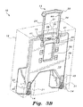
- the housing, retractable wheels, chassis sled and handle may be formed integrally with the piece of luggage 19, with the wheels 14 projecting through a pair of openings 21 formed in a lower wall of the article of luggage 19, and the handle 13 projecting through an opening 31 formed through an upper wall of the article of luggage.
- the chassis 10 is directed towards the combination of the housing 12 with the chassis sled 36, and it is to be understood that this combination may be utilized as a luggage carrier, such as that illustrated in Fig. 1 , or may be formed integrally with a piece of luggage, such as exemplary luggage 19, to form a piece of luggage with retractable wheels and a retractable handle.
- a luggage carrier such as that illustrated in Fig. 1
- exemplary luggage 19 to form a piece of luggage with retractable wheels and a retractable handle.
- the lower wall 34 of housing 12 is removed, as are straps 18, since, in this embodiment, there is no cargo to be secured to the housing 12.
- the rear wall 26 of housing 12 may have an upper opening 56 and a lower opening 58 formed therethrough, providing the user with rear access to the luggage 16, and further decreasing the mass of chassis 10 without a decrease in overall structural stability.
- Housing 12 further has an upper receptacle portion 28 formed adjacent the upper edge of rear wall 26.
- Upper receptacle portion 28 defines a recess 30, which releasably receives an upper gripping portion 22 of handle 13 (best shown in Fig. 3A ).
- Lower surface 15 of receptacle portion 2R further has a pair of handle openings 41 formed therethrough, for receiving vertical supports 24 of handle 13.
- lower surface 15 has a substantially centrally located opening 41 formed therethrough, providing the user with access to locking mechanism 40, which will be described in further detail below.
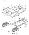
- the locking mechanism 40 is received within a lower receptacle portion 38, best shown in Fig. 2 .
- the lower portion of rear wall 26 has a pair of wheel openings 45 formed therethrough, allowing a pair of wheels 14 to at least partially project out of housing 12 when chassis 10 is in a deployed configuration, as will described in further detail below.
- a pair of adjustable straps 18 may be mounted to laterally opposed side edges of housing 12 for securing luggage 16 thereto. Straps 18 may include buckles 20 or any other suitable means for adjusting the length of straps 18.
- the internal skeletal structure 36 includes a pair of tubes 48 which slidably receive vertical supports 24 of handle 13.
- each vertical support 24 has a projecting member 82, e.g., a guide pin (which may be a spring-biased detent pin), formed on a lower portion thereof, which is received within a corresponding slot 84 formed through a front surface of the respective tube 48.
- a projecting member 82 e.g., a guide pin (which may be a spring-biased detent pin)
- Each slot extends in a substantially longitudinal direction.
- Tubes 48 are joined to one another, at their respective lower ends, by a transverse member or horizontal support 50, which is mounted between the respective lower ends and extends in the lateral direction.
- a pair of angled struts 52 are mounted to the lower ends of tubes 48 and project downwardly and outwardly therefrom, as shown.
- Tubes 48, transverse member 50, and struts 52 together form a chassis sled.
- a mounting plate 88 is joined to the lower end of each of angled struts 52 for the pivotal mounting of a lever arm 62 thereto.
- Lever arms 62 preferably have a substantially arcuate contour, as shown, and project downwardly from mounting plates 88.
- each lever arm 62 is pivotally mounted to the corresponding mounting plate 88 by a pivot pin 64 or the like.
- the lower end 68 of each lever arm 62 is pivotally joined to a corresponding wheel assembly 54 by a pivot pin 70 or the like.
- Each wheel assembly 54 includes a fender 74, which is mounted to a wheel lever 72 by a web.
- a lower end of each wheel lever 72 has a respective wheel 14 attached thereto by an axle 90, the wheel 14 being mounted for rotation on axle 90.
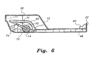
- Figs. 4 and 6 illustrate the luggage chassis 10 in a retracted configuration, with wheels 14 being fully received within housing 12.
- the fender 74 is contoured to provide stable contact with a lower rear inner wall of housing 12 when in the retracted state.
- a pair of horizontal rods 71, 73 are positioned within the lower portion of housing 12, with each rod 71, 73 extending in the lateral direction.
- a central portion of each lever arm 62 rests on horizontal rod 71 and a lower portion of each wheel lever 72 is positioned adjacent horizontal rod 73.
- the user pulls upwardly on the upper gripping portion 22 of handle 13 until the vertical supports 24 fully extend and the projecting member 82 reaches the top of the corresponding slot 84 in the front surface of the tubes 48, as shown in Figure 7 .
- the upward force is communicated through the vertical supports 24 to the tubes 48 causing the tubes 48 (and associated chassis sled 36) to move upwardly within housing 12. Since the housing 12 is not locked to the chassis sled at this time, the housing remains stationary while the chassis sled moves upwardly.
- Horizontal rods 71, 73 are mounted to the housing 12, rather than the chassis sled 36, and thus the horizontal rods 71, 73 do not move relative to the housing 12.
- the wheel lever 72 is initially in contact the horizontal rod 73, and the lever arm 62 is in contact with the horizontal rod 71.
- the upward movement of chassis sled 36 causes the wheel lever 72 to contact the horizontal rod 73.
- the horizontal rod 73 pushes outwardly on the wheel lever 72 thereby causing the wheel lever 72 to rotate in a direction indicated by directional arrow 80 shown in Fig. 5 .
- lever arms 62 pivot in the direction indicated by directional arrow 78 in Figure 5 .
- the wheel lever 72 loses contact with horizontal rod 73, and comes into contact with horizontal rod 71, which pushes the wheel lever 72 further outwardly and causes the wheels 14 to fully deploy. Movement of wheel lever 72 and lever arm 62 stops when the fender 74 contacts the lower inner wall of housing 12.
- the locking mechanism 40 includes a central cam knob 17 with a pair of rods 46 that extend laterally from opposite sides of the cam knob 17. Rotation of cam knob 17 to place the long axis of the cam between the heads of rods 46 compresses the springs 86 and drives the rods 46 outwardly and into holes 42 formed in vertical supports 24 and tubes 48 and thereby locks the chassis sled 36 to the housing 12.
- the cam knob 17 is rotated 90 degrees to 90° to place the short axis of the cam between the heads of rods 46, thereby expanding the springs 86 to and withdraw rods 46 from holes 42 in the support tubes 24 and tubes 48.
- the user In order to retract the chassis sled 12, the user unlocks the chassis sled 36 from the housing 12 and lowers the handle member 13, so that upper gripping portion 22 is received within recess 30 of receptacle portion 28.
- the downward movement of the handle 13 causes a downward movement of tubes 48.
- the downward movement of tubes 48 generates downward movement in the lever arms 62 and the wheel levers 72 with respect to housing 12, thereby causing the wheel levers 72 to pivot in a direction opposite that illustrated by directional arrow 80 in Fig. 5 .
- the fenders 74 cease pivotal movement when wheel levers 72 contact horizontal rod 73 and lever arms 62 once again rest on horizontal rod 71.
- fenders 74 in this retracted configuration, releasably cover and seal wheel openings 45, thus creating a continuous surface in rear wall 26, and protecting the wheels 14 from damage.
- the housing 12 is formed integrally within the piece of luggage 19.
- the lower wall 34 of housing 12 is removed, as housing 12 no longer receives luggage 16 or other cargo therein.
- straps 18 have further been removed, since housing 12, in the embodiment of Fig. 3B , is mounted within luggage 19, rather than carrying the luggage externally thereon.
- luggage 19 preferably has a pair of openings 21 formed through a lower portion thereof, for the wheels 14 to selectively project therethrough.
- an upper opening 31 is formed through an upper wall of luggage 19 for receiving handle 13.
Landscapes
- Engineering & Computer Science (AREA)
- Chemical & Material Sciences (AREA)
- Combustion & Propulsion (AREA)
- Transportation (AREA)
- Mechanical Engineering (AREA)
- Purses, Travelling Bags, Baskets, Or Suitcases (AREA)
- Handcart (AREA)
Claims (9)
- Chassis (10) mit einziehbaren Rädern (14), umfassend:a) ein Gehäuse (12), das einen hohlen Innenraum definiert und einen unteren Bereich aufweist, der ein Paar durch das Gehäuse hindurch ausgebildete Radöffnungen (45) aufweist;b) ein Chassis-Schlitten (36), der im Gehäuse (12) verschiebbar angeordnet ist;c) ein Paar Hebelarme (62), wobei jeder Hebelarm (62) im unteren Bereich des Gehäuses (12) angeordnet ist und jeder der Hebelarme (62) ein erstes Ende, das drehbar am Chassis-Schlitten (36) angebracht ist, und ein zweites Ende aufweist;d) ein Paar Radaufhängungen (54), wobei jede Radaufhängung (54) einen Radarm (72), eine Abdeckung (74), die die Radöffnungen in eingezogener Position abdecken kann, und eine Fläche aufweist, die die Abdeckung (74) mit dem Radarm (72) verbindet, wobei die Radarme (72) ein erstes Ende, das drehbar mit dem zweiten Ende eines Hebelarms (62) verbunden ist, und ein zweites Ende aufweisen;e) eine Achse (90), die am zweiten Ende jedes der Radarme (72) befestigt ist, und ein Rad (14), das auf jeder der Achsen (90) drehbar befestigt ist;f) zwei Paare horizontaler Stäbe (71, 73), die sich vom unteren Bereich des Gehäuses (12) seitlich erstrecken, wobei jedes der Stabpaare (71, 73) Schwenkpositionen für jeden der Radarme (72) definiert;g) eine Griffeinrichtung, die mit dem Chassis-Schlitten (36) verbunden ist;h) einen Einrastmechanismus, der den Chassis-Schlitten (36) am Gehäuse selektiv einrasten kann, wobei der Einrastmechanismus (40) eine eingerastete Position und eine gelöste Position aufweist;wobei die Räder (14) so eingerichtet sind, dass sie in eine ausgefahrene Position außerhalb des Gehäuses (12) schwenken können, wenn der Griff bei gelöster Position des Einrastmechanismus aus dem Gehäuse (12) gezogen wird, und so eingerichtet sind, dass sie in eine eingezogene Position schwenken können, wenn der Griff in das Gehäuse hineingeschoben wird;
dadurch gekennzeichnet, dass
eine Aufwärtsbewegung des Chassis-Schlittens (36) bewirkt, dass jeder Radarm (72) einen ersten horizontalen Stab (73) berührt und dass der erste horizontale Stab (73) sich auswärts auf den Radarm (72) zuschiebt, wodurch der Radarm (72) vom Hebelarm (62) wegschwenkt, und eine weitere Aufwärtsbewegung des Chassis-Schlittens (36) bewirkt, dass jeder Radarm (72) Kontakt mit dem ersten horizontalen Stab (73) verliert und in Kontakt mit einem zweiten horizontalen Stab (71) tritt, was die Radarme (72) weiter auswärts schiebt und bewirkt, dass die Räder (14) sich vollständig außerhalb der Radöffnungen entfalten. - Das Chassis mit einziehbaren Rädern (14) gemäß Anspruch 1, wobei der Chassis-Schlitten (36) ein Paar parallele Röhren, die lange, sich axial erstreckende Führungsöffnungen definieren, eine Verstrebung, die die unteren Enden der Röhren miteinander verbindet, und Radaufhängungstragstücke (52) aufweist, die sich von den unteren Enden der Röhren erstrecken, wobei jedes der Tragstücke (52) mit einem der Hebelarme (62) verbunden ist.
- Das Chassis mit einziehbaren Rädern (14) gemäß Anspruch 2, wobei die Griffeinrichtung einen länglichen Griff und vertikale Stützröhren (24) aufweist, die sich von gegenüber liegenden Enden des Griffs aus erstrecken, wobei jede der vertikalen Stützröhren (24) ein hervorstehendes Element (82) aufweist, das in der sich axial erstreckenden Führungsöffnung, die in den Röhren des Chassis-Schlittens definiert ist, verschiebbar ist.
- Das Chassis mit einziehbaren Rädern gemäß Anspruch 3, wobei der Einrastmechanismus einen drehbaren Nockendrehknopf (17) und unter Federvorspannung stehende Verschließstäbe aufweist, die in dem Gehäuse vorliegen und sich auf gegenüberliegenden Seiten des Nockendrehknopfs (17) erstrecken, wobei der Nockendrehknopf (17) eine Verschlussposition hat, bei der sich die Verschließstäbe durch die vertikalen Stützröhren (24) und die Röhren des Chassis-Schlittens erstreckt, und eine unverschlossene Position, in der sich die Verschließstäbe von den vertikalen Stützröhren (24) zurückziehen.
- Das Chassis mit einziehbaren Rädern gemäß Anspruch 4, wobei mindestens eine Seite des Gehäuses (12) einen Container aufweist, der an das Gehäuse (12) anschließt.
- Das Chassis mit einziehbaren Rädern gemäß Anspruch 5, wobei der Container ein Gepäckstück ist.
- Das Chassis mit einziehbaren Rädern gemäß Anspruch 4, wobei sich eine Basis senkrecht von dem Gehäuse erstreckt.
- Das Chassis mit einziehbaren Rädern gemäß Anspruch 7, ferner umfassend eine Sicherungseinrichtung, um Ladung am Chassis zu sichern.
- Das Chassis mit einziehbaren Rädern gemäß Anspruch 8, wobei die Sicherungseinrichtung mindestens einen Gurt umfasst und die Ladung Gepäck umfasst.
Applications Claiming Priority (2)
| Application Number | Priority Date | Filing Date | Title |
|---|---|---|---|
| US81109806P | 2006-06-06 | 2006-06-06 | |
| PCT/US2007/008364 WO2007145699A2 (en) | 2006-06-06 | 2007-04-05 | Chassis with retractable wheels for wheeled products |
Publications (3)
| Publication Number | Publication Date |
|---|---|
| EP2024218A2 EP2024218A2 (de) | 2009-02-18 |
| EP2024218A4 EP2024218A4 (de) | 2009-11-11 |
| EP2024218B1 true EP2024218B1 (de) | 2012-10-03 |
Family
ID=38832253
Family Applications (1)
| Application Number | Title | Priority Date | Filing Date |
|---|---|---|---|
| EP07754822A Not-in-force EP2024218B1 (de) | 2006-06-06 | 2007-04-05 | Chassis mit einziehbaren rädern für mit rädern versehene produkte |
Country Status (3)
| Country | Link |
|---|---|
| EP (1) | EP2024218B1 (de) |
| JP (1) | JP2009539469A (de) |
| WO (1) | WO2007145699A2 (de) |
Cited By (2)
| Publication number | Priority date | Publication date | Assignee | Title |
|---|---|---|---|---|
| US10086508B2 (en) | 2014-07-22 | 2018-10-02 | Milwaukee Electric Tool Corporation | Tool storage devices |
| USD844324S1 (en) | 2015-07-17 | 2019-04-02 | Milwaukee Electric Tool Corporation | Bag |
Families Citing this family (28)
| Publication number | Priority date | Publication date | Assignee | Title |
|---|---|---|---|---|
| US7997591B2 (en) | 2007-04-05 | 2011-08-16 | Retrac Enterprises, Inc. | Chassis with retractable wheels |
| US8757642B2 (en) * | 2012-05-22 | 2014-06-24 | Retract Enterprises Inc | Retractable wheel assembly |
| GB2512592B (en) * | 2013-04-02 | 2015-08-05 | David Ehrentreu | A compact suitcase |
| US20150336220A1 (en) * | 2014-05-23 | 2015-11-26 | Illinois Tool Works Inc. | Running gear system for portable wire feeder |
| JP6071968B2 (ja) * | 2014-09-26 | 2017-02-01 | 株式会社サンカ | 牽引走行式収納ボックス |
| KR101702498B1 (ko) * | 2015-09-03 | 2017-02-06 | 김준호 | 캐리어 가방 |
| US9872547B2 (en) | 2015-11-25 | 2018-01-23 | Milwaukee Electric Tool Corporation | Handle assembly for a case |
| US12108853B2 (en) | 2019-01-06 | 2024-10-08 | Yeti Coolers, Llc | Luggage system |
| CN116729803B (zh) | 2017-06-12 | 2026-06-09 | 野醍冷却器有限责任公司 | 容器和闩锁组件 |
| US11685573B2 (en) | 2017-06-12 | 2023-06-27 | Yeti Coolers, Llc | Carry strap for container |
| US11976498B2 (en) | 2017-06-12 | 2024-05-07 | Yeti Coolers, Llc | Container and latching system |
| AU201717615S (en) | 2017-06-12 | 2018-01-15 | Yeti Coolers | Container |
| USD904829S1 (en) | 2018-12-11 | 2020-12-15 | Yeti Coolers, Llc | Container accessories |
| USD907445S1 (en) | 2018-12-11 | 2021-01-12 | Yeti Coolers, Llc | Container accessories |
| US12225993B2 (en) | 2019-01-06 | 2025-02-18 | Yeti Coolers, Llc | Luggage system |
| JP7303313B2 (ja) | 2019-01-06 | 2023-07-04 | イエティ クーラーズ エルエルシー | 荷物システム |
| KR102237091B1 (ko) * | 2019-11-26 | 2021-04-06 | 곽상훈 | 탈부착 가능한 캐리어용 휠장치 |
| USD961926S1 (en) | 2020-06-30 | 2022-08-30 | Yeti Coolers, Llc | Luggage |
| USD951643S1 (en) | 2020-06-30 | 2022-05-17 | Yeti Coolers, Llc | Luggage |
| USD963344S1 (en) | 2020-06-30 | 2022-09-13 | Yeti Coolers, Llc | Luggage |
| USD954436S1 (en) | 2020-06-30 | 2022-06-14 | Yeti Coolers, Llc | Luggage |
| USD994438S1 (en) | 2020-12-16 | 2023-08-08 | Yeti Coolers, Llc | Container |
| USD985937S1 (en) | 2020-12-16 | 2023-05-16 | Yeti Coolers, Llc | Container |
| USD960648S1 (en) | 2020-12-16 | 2022-08-16 | Yeti Coolers, Llc | Container accessory |
| US12661733B2 (en) | 2021-04-30 | 2026-06-23 | Illinois Tool Works Inc. | Welding system with support base |
| KR102575651B1 (ko) * | 2022-03-30 | 2023-09-06 | 동국대학교 와이즈캠퍼스 산학협력단 | 캐리어 가방용 바퀴 모듈 |
| CN115005576B (zh) * | 2022-05-06 | 2024-02-27 | 泉州锦林环保高新材料有限公司 | 一种轮子可收放的拉杆箱 |
| CN119840349B (zh) * | 2023-10-17 | 2026-06-19 | 上海理想汽车科技有限公司 | 伸缩轮机构及箱体 |
Family Cites Families (17)
| Publication number | Priority date | Publication date | Assignee | Title |
|---|---|---|---|---|
| US44936A (en) * | 1864-11-08 | Improvement in trunks | ||
| US2765178A (en) * | 1954-11-18 | 1956-10-02 | Wallace Lauretta Craig | Folding shopping carrier |
| AT260698B (de) * | 1965-06-16 | 1968-03-11 | Schuster Wilhelm | Fahrzeug, insbesondere Sport- oder Rettungsgerät |
| JPH041017Y2 (de) * | 1986-06-09 | 1992-01-14 | ||
| JPH04131317U (ja) * | 1991-05-24 | 1992-12-02 | 株式会社ナカネ | キヤリー内蔵式バツグ |
| US5431262A (en) * | 1993-10-08 | 1995-07-11 | Royalox International, Inc. | Combined rollable case and carrier |
| US5524737A (en) * | 1994-07-29 | 1996-06-11 | Wang; King-Sheng | Retractable handle and wheel assembly for travel bags |
| JPH0847413A (ja) * | 1994-08-04 | 1996-02-20 | Kyowa:Kk | 鞄の曳行ハンドル |
| US5533231A (en) * | 1994-09-12 | 1996-07-09 | Bai; Yang-Fong | Concealable caster of baggage |
| US5513873A (en) * | 1994-10-18 | 1996-05-07 | Chen; Shou-Mao | Adjustable handle assembly for push cart |
| US5816374A (en) * | 1996-02-16 | 1998-10-06 | Chaw Khong Technology Co., Ltd. | Lock mechanism of a pull handle assembly for a wheeled suitcase |
| US5813503A (en) * | 1996-11-18 | 1998-09-29 | Chang; Yuan-Chi | Luggage case structure with retrievable handle and wheels |
| JPH11196916A (ja) * | 1997-10-10 | 1999-07-27 | Applied Sewing Resources | 鞄 |
| EP1059859A4 (de) * | 1998-03-04 | 2004-09-08 | 500 Group Inc | Verbesserungen für gepäck mit laufrollen |
| JP3082024U (ja) * | 2001-05-23 | 2001-11-30 | 方 志忠 | 折畳方式手荷物車の構造 |
| US6604615B2 (en) * | 2001-11-07 | 2003-08-12 | Yi-Ming Wu | Roller device of luggage case |
| JP3793174B2 (ja) * | 2003-05-21 | 2006-07-05 | 株式会社スワニー | キャスター付きの鞄 |
-
2007
- 2007-04-05 EP EP07754822A patent/EP2024218B1/de not_active Not-in-force
- 2007-04-05 WO PCT/US2007/008364 patent/WO2007145699A2/en not_active Ceased
- 2007-04-05 JP JP2009514257A patent/JP2009539469A/ja active Pending
Cited By (2)
| Publication number | Priority date | Publication date | Assignee | Title |
|---|---|---|---|---|
| US10086508B2 (en) | 2014-07-22 | 2018-10-02 | Milwaukee Electric Tool Corporation | Tool storage devices |
| USD844324S1 (en) | 2015-07-17 | 2019-04-02 | Milwaukee Electric Tool Corporation | Bag |
Also Published As
| Publication number | Publication date |
|---|---|
| JP2009539469A (ja) | 2009-11-19 |
| EP2024218A2 (de) | 2009-02-18 |
| WO2007145699A2 (en) | 2007-12-21 |
| WO2007145699A3 (en) | 2008-12-04 |
| EP2024218A4 (de) | 2009-11-11 |
Similar Documents
| Publication | Publication Date | Title |
|---|---|---|
| US7997591B2 (en) | Chassis with retractable wheels | |
| EP2024218A2 (de) | Chassis mit einziehbaren rädern für mit rädern versehen produkte | |
| US5568848A (en) | Laterally movable suitcase with wheeled, pivotable leg | |
| US8490765B2 (en) | Luggage | |
| US6662916B2 (en) | Wheeled luggage and associated devices | |
| US6575493B1 (en) | Collapsible trolley | |
| US7748508B2 (en) | Wheeled luggage case | |
| US7614628B2 (en) | Convertible carrying case systems and collapsible wheeled carts for carrying cases | |
| US20150342318A1 (en) | Wheeled assembly | |
| US7427080B2 (en) | Shopping trolleys | |
| US6012729A (en) | Luggage system and folding dolly therefor | |
| US6832670B2 (en) | Convertible travel case | |
| WO1998008721A1 (en) | Suitcase and cart assembly | |
| WO2002085682A1 (en) | Folding cart | |
| GB2197637A (en) | Wheeled case having retractable handle | |
| GB2443945A (en) | Luggage with flexible handle | |
| GB2436486A (en) | Wheeled luggage with retractable steering wheel assembly | |
| WO2013037845A2 (en) | Wheeled box unit and arrangement with standing board |
Legal Events
| Date | Code | Title | Description |
|---|---|---|---|
| PUAI | Public reference made under article 153(3) epc to a published international application that has entered the european phase |
Free format text: ORIGINAL CODE: 0009012 |
|
| 17P | Request for examination filed |
Effective date: 20081203 |
|
| AK | Designated contracting states |
Kind code of ref document: A2 Designated state(s): AT BE BG CH CY CZ DE DK EE ES FI FR GB GR HU IE IS IT LI LT LU LV MC MT NL PL PT RO SE SI SK TR |
|
| AX | Request for extension of the european patent |
Extension state: AL BA HR MK RS |
|
| A4 | Supplementary search report drawn up and despatched |
Effective date: 20091014 |
|
| DAX | Request for extension of the european patent (deleted) | ||
| RIC1 | Information provided on ipc code assigned before grant |
Ipc: A45C 13/26 20060101ALI20091008BHEP Ipc: B62B 1/26 20060101ALI20091008BHEP Ipc: B62B 1/12 20060101ALI20091008BHEP Ipc: A45C 5/14 20060101AFI20091008BHEP Ipc: A45C 13/36 20060101ALI20091008BHEP |
|
| 17Q | First examination report despatched |
Effective date: 20100201 |
|
| GRAC | Information related to communication of intention to grant a patent modified |
Free format text: ORIGINAL CODE: EPIDOSCIGR1 |
|
| GRAP | Despatch of communication of intention to grant a patent |
Free format text: ORIGINAL CODE: EPIDOSNIGR1 |
|
| GRAS | Grant fee paid |
Free format text: ORIGINAL CODE: EPIDOSNIGR3 |
|
| GRAA | (expected) grant |
Free format text: ORIGINAL CODE: 0009210 |
|
| AK | Designated contracting states |
Kind code of ref document: B1 Designated state(s): AT BE BG CH CY CZ DE DK EE ES FI FR GB GR HU IE IS IT LI LT LU LV MC MT NL PL PT RO SE SI SK TR |
|
| REG | Reference to a national code |
Ref country code: GB Ref legal event code: FG4D |
|
| REG | Reference to a national code |
Ref country code: AT Ref legal event code: REF Ref document number: 577567 Country of ref document: AT Kind code of ref document: T Effective date: 20121015 Ref country code: CH Ref legal event code: EP |
|
| REG | Reference to a national code |
Ref country code: IE Ref legal event code: FG4D |
|
| REG | Reference to a national code |
Ref country code: DE Ref legal event code: R096 Ref document number: 602007025870 Country of ref document: DE Effective date: 20121129 |
|
| REG | Reference to a national code |
Ref country code: AT Ref legal event code: MK05 Ref document number: 577567 Country of ref document: AT Kind code of ref document: T Effective date: 20121003 |
|
| PG25 | Lapsed in a contracting state [announced via postgrant information from national office to epo] |
Ref country code: SI Free format text: LAPSE BECAUSE OF FAILURE TO SUBMIT A TRANSLATION OF THE DESCRIPTION OR TO PAY THE FEE WITHIN THE PRESCRIBED TIME-LIMIT Effective date: 20121003 |
|
| REG | Reference to a national code |
Ref country code: NL Ref legal event code: VDEP Effective date: 20121003 |
|
| REG | Reference to a national code |
Ref country code: LT Ref legal event code: MG4D |
|
| PG25 | Lapsed in a contracting state [announced via postgrant information from national office to epo] |
Ref country code: NL Free format text: LAPSE BECAUSE OF FAILURE TO SUBMIT A TRANSLATION OF THE DESCRIPTION OR TO PAY THE FEE WITHIN THE PRESCRIBED TIME-LIMIT Effective date: 20121003 Ref country code: ES Free format text: LAPSE BECAUSE OF FAILURE TO SUBMIT A TRANSLATION OF THE DESCRIPTION OR TO PAY THE FEE WITHIN THE PRESCRIBED TIME-LIMIT Effective date: 20130114 Ref country code: LT Free format text: LAPSE BECAUSE OF FAILURE TO SUBMIT A TRANSLATION OF THE DESCRIPTION OR TO PAY THE FEE WITHIN THE PRESCRIBED TIME-LIMIT Effective date: 20121003 Ref country code: SE Free format text: LAPSE BECAUSE OF FAILURE TO SUBMIT A TRANSLATION OF THE DESCRIPTION OR TO PAY THE FEE WITHIN THE PRESCRIBED TIME-LIMIT Effective date: 20121003 Ref country code: IS Free format text: LAPSE BECAUSE OF FAILURE TO SUBMIT A TRANSLATION OF THE DESCRIPTION OR TO PAY THE FEE WITHIN THE PRESCRIBED TIME-LIMIT Effective date: 20130203 Ref country code: FI Free format text: LAPSE BECAUSE OF FAILURE TO SUBMIT A TRANSLATION OF THE DESCRIPTION OR TO PAY THE FEE WITHIN THE PRESCRIBED TIME-LIMIT Effective date: 20121003 |
|
| PG25 | Lapsed in a contracting state [announced via postgrant information from national office to epo] |
Ref country code: GR Free format text: LAPSE BECAUSE OF FAILURE TO SUBMIT A TRANSLATION OF THE DESCRIPTION OR TO PAY THE FEE WITHIN THE PRESCRIBED TIME-LIMIT Effective date: 20130104 Ref country code: BE Free format text: LAPSE BECAUSE OF FAILURE TO SUBMIT A TRANSLATION OF THE DESCRIPTION OR TO PAY THE FEE WITHIN THE PRESCRIBED TIME-LIMIT Effective date: 20121003 Ref country code: PL Free format text: LAPSE BECAUSE OF FAILURE TO SUBMIT A TRANSLATION OF THE DESCRIPTION OR TO PAY THE FEE WITHIN THE PRESCRIBED TIME-LIMIT Effective date: 20121003 Ref country code: PT Free format text: LAPSE BECAUSE OF FAILURE TO SUBMIT A TRANSLATION OF THE DESCRIPTION OR TO PAY THE FEE WITHIN THE PRESCRIBED TIME-LIMIT Effective date: 20130204 Ref country code: LV Free format text: LAPSE BECAUSE OF FAILURE TO SUBMIT A TRANSLATION OF THE DESCRIPTION OR TO PAY THE FEE WITHIN THE PRESCRIBED TIME-LIMIT Effective date: 20121003 |
|
| PG25 | Lapsed in a contracting state [announced via postgrant information from national office to epo] |
Ref country code: AT Free format text: LAPSE BECAUSE OF FAILURE TO SUBMIT A TRANSLATION OF THE DESCRIPTION OR TO PAY THE FEE WITHIN THE PRESCRIBED TIME-LIMIT Effective date: 20121003 |
|
| PG25 | Lapsed in a contracting state [announced via postgrant information from national office to epo] |
Ref country code: BG Free format text: LAPSE BECAUSE OF FAILURE TO SUBMIT A TRANSLATION OF THE DESCRIPTION OR TO PAY THE FEE WITHIN THE PRESCRIBED TIME-LIMIT Effective date: 20130103 Ref country code: CZ Free format text: LAPSE BECAUSE OF FAILURE TO SUBMIT A TRANSLATION OF THE DESCRIPTION OR TO PAY THE FEE WITHIN THE PRESCRIBED TIME-LIMIT Effective date: 20121003 Ref country code: DK Free format text: LAPSE BECAUSE OF FAILURE TO SUBMIT A TRANSLATION OF THE DESCRIPTION OR TO PAY THE FEE WITHIN THE PRESCRIBED TIME-LIMIT Effective date: 20121003 Ref country code: SK Free format text: LAPSE BECAUSE OF FAILURE TO SUBMIT A TRANSLATION OF THE DESCRIPTION OR TO PAY THE FEE WITHIN THE PRESCRIBED TIME-LIMIT Effective date: 20121003 Ref country code: EE Free format text: LAPSE BECAUSE OF FAILURE TO SUBMIT A TRANSLATION OF THE DESCRIPTION OR TO PAY THE FEE WITHIN THE PRESCRIBED TIME-LIMIT Effective date: 20121003 |
|
| PLBE | No opposition filed within time limit |
Free format text: ORIGINAL CODE: 0009261 |
|
| STAA | Information on the status of an ep patent application or granted ep patent |
Free format text: STATUS: NO OPPOSITION FILED WITHIN TIME LIMIT |
|
| PG25 | Lapsed in a contracting state [announced via postgrant information from national office to epo] |
Ref country code: IT Free format text: LAPSE BECAUSE OF FAILURE TO SUBMIT A TRANSLATION OF THE DESCRIPTION OR TO PAY THE FEE WITHIN THE PRESCRIBED TIME-LIMIT Effective date: 20121003 Ref country code: RO Free format text: LAPSE BECAUSE OF FAILURE TO SUBMIT A TRANSLATION OF THE DESCRIPTION OR TO PAY THE FEE WITHIN THE PRESCRIBED TIME-LIMIT Effective date: 20121003 |
|
| 26N | No opposition filed |
Effective date: 20130704 |
|
| REG | Reference to a national code |
Ref country code: DE Ref legal event code: R097 Ref document number: 602007025870 Country of ref document: DE Effective date: 20130704 |
|
| PG25 | Lapsed in a contracting state [announced via postgrant information from national office to epo] |
Ref country code: CY Free format text: LAPSE BECAUSE OF FAILURE TO SUBMIT A TRANSLATION OF THE DESCRIPTION OR TO PAY THE FEE WITHIN THE PRESCRIBED TIME-LIMIT Effective date: 20121003 Ref country code: MC Free format text: LAPSE BECAUSE OF FAILURE TO SUBMIT A TRANSLATION OF THE DESCRIPTION OR TO PAY THE FEE WITHIN THE PRESCRIBED TIME-LIMIT Effective date: 20121003 |
|
| REG | Reference to a national code |
Ref country code: CH Ref legal event code: PL |
|
| GBPC | Gb: european patent ceased through non-payment of renewal fee |
Effective date: 20130405 |
|
| REG | Reference to a national code |
Ref country code: IE Ref legal event code: MM4A |
|
| PG25 | Lapsed in a contracting state [announced via postgrant information from national office to epo] |
Ref country code: GB Free format text: LAPSE BECAUSE OF NON-PAYMENT OF DUE FEES Effective date: 20130405 Ref country code: DE Free format text: LAPSE BECAUSE OF NON-PAYMENT OF DUE FEES Effective date: 20131101 Ref country code: LI Free format text: LAPSE BECAUSE OF NON-PAYMENT OF DUE FEES Effective date: 20130430 Ref country code: CH Free format text: LAPSE BECAUSE OF NON-PAYMENT OF DUE FEES Effective date: 20130430 |
|
| REG | Reference to a national code |
Ref country code: FR Ref legal event code: ST Effective date: 20131231 |
|
| REG | Reference to a national code |
Ref country code: DE Ref legal event code: R119 Ref document number: 602007025870 Country of ref document: DE Effective date: 20131101 |
|
| PG25 | Lapsed in a contracting state [announced via postgrant information from national office to epo] |
Ref country code: FR Free format text: LAPSE BECAUSE OF NON-PAYMENT OF DUE FEES Effective date: 20130430 |
|
| PG25 | Lapsed in a contracting state [announced via postgrant information from national office to epo] |
Ref country code: IE Free format text: LAPSE BECAUSE OF NON-PAYMENT OF DUE FEES Effective date: 20130405 |
|
| PG25 | Lapsed in a contracting state [announced via postgrant information from national office to epo] |
Ref country code: MT Free format text: LAPSE BECAUSE OF FAILURE TO SUBMIT A TRANSLATION OF THE DESCRIPTION OR TO PAY THE FEE WITHIN THE PRESCRIBED TIME-LIMIT Effective date: 20121003 |
|
| PG25 | Lapsed in a contracting state [announced via postgrant information from national office to epo] |
Ref country code: TR Free format text: LAPSE BECAUSE OF FAILURE TO SUBMIT A TRANSLATION OF THE DESCRIPTION OR TO PAY THE FEE WITHIN THE PRESCRIBED TIME-LIMIT Effective date: 20121003 |
|
| PG25 | Lapsed in a contracting state [announced via postgrant information from national office to epo] |
Ref country code: LU Free format text: LAPSE BECAUSE OF NON-PAYMENT OF DUE FEES Effective date: 20130405 Ref country code: HU Free format text: LAPSE BECAUSE OF FAILURE TO SUBMIT A TRANSLATION OF THE DESCRIPTION OR TO PAY THE FEE WITHIN THE PRESCRIBED TIME-LIMIT; INVALID AB INITIO Effective date: 20070405 |