EP2024651B2 - Selbststanznietung - Google Patents
Selbststanznietung Download PDFInfo
- Publication number
- EP2024651B2 EP2024651B2 EP07732751.8A EP07732751A EP2024651B2 EP 2024651 B2 EP2024651 B2 EP 2024651B2 EP 07732751 A EP07732751 A EP 07732751A EP 2024651 B2 EP2024651 B2 EP 2024651B2
- Authority
- EP
- European Patent Office
- Prior art keywords
- rivet
- shank
- bore
- piercing
- self
- Prior art date
- Legal status (The legal status is an assumption and is not a legal conclusion. Google has not performed a legal analysis and makes no representation as to the accuracy of the status listed.)
- Active
Links
Images



Classifications
-
- B—PERFORMING OPERATIONS; TRANSPORTING
- B21—MECHANICAL METAL-WORKING WITHOUT ESSENTIALLY REMOVING MATERIAL; PUNCHING METAL
- B21J—FORGING; HAMMERING; PRESSING METAL; RIVETING; FORGE FURNACES
- B21J15/00—Riveting
- B21J15/02—Riveting procedures
- B21J15/025—Setting self-piercing rivets
-
- F—MECHANICAL ENGINEERING; LIGHTING; HEATING; WEAPONS; BLASTING
- F16—ENGINEERING ELEMENTS AND UNITS; GENERAL MEASURES FOR PRODUCING AND MAINTAINING EFFECTIVE FUNCTIONING OF MACHINES OR INSTALLATIONS; THERMAL INSULATION IN GENERAL
- F16B—DEVICES FOR FASTENING OR SECURING CONSTRUCTIONAL ELEMENTS OR MACHINE PARTS TOGETHER, e.g. NAILS, BOLTS, CIRCLIPS, CLAMPS, CLIPS OR WEDGES; JOINTS OR JOINTING
- F16B19/00—Bolts without screw-thread; Pins, including deformable elements; Rivets
- F16B19/04—Rivets; Spigots or the like fastened by riveting
- F16B19/08—Hollow rivets; Multi-part rivets
- F16B19/086—Self-piercing rivets
-
- Y—GENERAL TAGGING OF NEW TECHNOLOGICAL DEVELOPMENTS; GENERAL TAGGING OF CROSS-SECTIONAL TECHNOLOGIES SPANNING OVER SEVERAL SECTIONS OF THE IPC; TECHNICAL SUBJECTS COVERED BY FORMER USPC CROSS-REFERENCE ART COLLECTIONS [XRACs] AND DIGESTS
- Y10—TECHNICAL SUBJECTS COVERED BY FORMER USPC
- Y10T—TECHNICAL SUBJECTS COVERED BY FORMER US CLASSIFICATION
- Y10T29/00—Metal working
- Y10T29/49—Method of mechanical manufacture
- Y10T29/49826—Assembling or joining
- Y10T29/49833—Punching, piercing or reaming part by surface of second part
- Y10T29/49835—Punching, piercing or reaming part by surface of second part with shaping
-
- Y—GENERAL TAGGING OF NEW TECHNOLOGICAL DEVELOPMENTS; GENERAL TAGGING OF CROSS-SECTIONAL TECHNOLOGIES SPANNING OVER SEVERAL SECTIONS OF THE IPC; TECHNICAL SUBJECTS COVERED BY FORMER USPC CROSS-REFERENCE ART COLLECTIONS [XRACs] AND DIGESTS
- Y10—TECHNICAL SUBJECTS COVERED BY FORMER USPC
- Y10T—TECHNICAL SUBJECTS COVERED BY FORMER US CLASSIFICATION
- Y10T29/00—Metal working
- Y10T29/49—Method of mechanical manufacture
- Y10T29/49826—Assembling or joining
- Y10T29/49833—Punching, piercing or reaming part by surface of second part
- Y10T29/49835—Punching, piercing or reaming part by surface of second part with shaping
- Y10T29/49837—Punching, piercing or reaming part by surface of second part with shaping of first part
-
- Y—GENERAL TAGGING OF NEW TECHNOLOGICAL DEVELOPMENTS; GENERAL TAGGING OF CROSS-SECTIONAL TECHNOLOGIES SPANNING OVER SEVERAL SECTIONS OF THE IPC; TECHNICAL SUBJECTS COVERED BY FORMER USPC CROSS-REFERENCE ART COLLECTIONS [XRACs] AND DIGESTS
- Y10—TECHNICAL SUBJECTS COVERED BY FORMER USPC
- Y10T—TECHNICAL SUBJECTS COVERED BY FORMER US CLASSIFICATION
- Y10T29/00—Metal working
- Y10T29/49—Method of mechanical manufacture
- Y10T29/49826—Assembling or joining
- Y10T29/49908—Joining by deforming
- Y10T29/49938—Radially expanding part in cavity, aperture, or hollow body
- Y10T29/49943—Riveting
-
- Y—GENERAL TAGGING OF NEW TECHNOLOGICAL DEVELOPMENTS; GENERAL TAGGING OF CROSS-SECTIONAL TECHNOLOGIES SPANNING OVER SEVERAL SECTIONS OF THE IPC; TECHNICAL SUBJECTS COVERED BY FORMER USPC CROSS-REFERENCE ART COLLECTIONS [XRACs] AND DIGESTS
- Y10—TECHNICAL SUBJECTS COVERED BY FORMER USPC
- Y10T—TECHNICAL SUBJECTS COVERED BY FORMER US CLASSIFICATION
- Y10T29/00—Metal working
- Y10T29/49—Method of mechanical manufacture
- Y10T29/49826—Assembling or joining
- Y10T29/49947—Assembling or joining by applying separate fastener
-
- Y—GENERAL TAGGING OF NEW TECHNOLOGICAL DEVELOPMENTS; GENERAL TAGGING OF CROSS-SECTIONAL TECHNOLOGIES SPANNING OVER SEVERAL SECTIONS OF THE IPC; TECHNICAL SUBJECTS COVERED BY FORMER USPC CROSS-REFERENCE ART COLLECTIONS [XRACs] AND DIGESTS
- Y10—TECHNICAL SUBJECTS COVERED BY FORMER USPC
- Y10T—TECHNICAL SUBJECTS COVERED BY FORMER US CLASSIFICATION
- Y10T29/00—Metal working
- Y10T29/49—Method of mechanical manufacture
- Y10T29/49826—Assembling or joining
- Y10T29/49947—Assembling or joining by applying separate fastener
- Y10T29/49954—Fastener deformed after application
- Y10T29/49956—Riveting
-
- Y—GENERAL TAGGING OF NEW TECHNOLOGICAL DEVELOPMENTS; GENERAL TAGGING OF CROSS-SECTIONAL TECHNOLOGIES SPANNING OVER SEVERAL SECTIONS OF THE IPC; TECHNICAL SUBJECTS COVERED BY FORMER USPC CROSS-REFERENCE ART COLLECTIONS [XRACs] AND DIGESTS
- Y10—TECHNICAL SUBJECTS COVERED BY FORMER USPC
- Y10T—TECHNICAL SUBJECTS COVERED BY FORMER US CLASSIFICATION
- Y10T29/00—Metal working
- Y10T29/53—Means to assemble or disassemble
- Y10T29/5343—Means to drive self-piercing work part
-
- Y—GENERAL TAGGING OF NEW TECHNOLOGICAL DEVELOPMENTS; GENERAL TAGGING OF CROSS-SECTIONAL TECHNOLOGIES SPANNING OVER SEVERAL SECTIONS OF THE IPC; TECHNICAL SUBJECTS COVERED BY FORMER USPC CROSS-REFERENCE ART COLLECTIONS [XRACs] AND DIGESTS
- Y10—TECHNICAL SUBJECTS COVERED BY FORMER USPC
- Y10T—TECHNICAL SUBJECTS COVERED BY FORMER US CLASSIFICATION
- Y10T29/00—Metal working
- Y10T29/53—Means to assemble or disassemble
- Y10T29/53709—Overedge assembling means
- Y10T29/5377—Riveter
-
- Y—GENERAL TAGGING OF NEW TECHNOLOGICAL DEVELOPMENTS; GENERAL TAGGING OF CROSS-SECTIONAL TECHNOLOGIES SPANNING OVER SEVERAL SECTIONS OF THE IPC; TECHNICAL SUBJECTS COVERED BY FORMER USPC CROSS-REFERENCE ART COLLECTIONS [XRACs] AND DIGESTS
- Y10—TECHNICAL SUBJECTS COVERED BY FORMER USPC
- Y10T—TECHNICAL SUBJECTS COVERED BY FORMER US CLASSIFICATION
- Y10T403/00—Joints and connections
- Y10T403/49—Member deformed in situ
- Y10T403/4974—Member deformed in situ by piercing
-
- Y—GENERAL TAGGING OF NEW TECHNOLOGICAL DEVELOPMENTS; GENERAL TAGGING OF CROSS-SECTIONAL TECHNOLOGIES SPANNING OVER SEVERAL SECTIONS OF THE IPC; TECHNICAL SUBJECTS COVERED BY FORMER USPC CROSS-REFERENCE ART COLLECTIONS [XRACs] AND DIGESTS
- Y10—TECHNICAL SUBJECTS COVERED BY FORMER USPC
- Y10T—TECHNICAL SUBJECTS COVERED BY FORMER US CLASSIFICATION
- Y10T403/00—Joints and connections
- Y10T403/49—Member deformed in situ
- Y10T403/4991—Both members deformed
Definitions
- the present invention relates to a self-piercing rivet and more particularly to a self-piercing rivet of the kind that is inserted into sheet material without full penetration such that a deformed end of the rivet remains encapsulated by an upset annulus of the sheet material.
- the invention also relates to a riveting method and a system for the insertion of such a rivet.
- US 6,385,843 discloses a self-piercing rivet that has proved commercially successful.
- the rivet has a deep central bore with a rounded base and a conical entrance having a generally curved surface.
- US 6,325,584 shows a partially hollow self-piercing rivet for joining aluminium sheet.
- the rivet is specifically designed to be made of light metal with low tensile strength and has a central bore that is shallow and conical.
- the piercing end of the rivet is as blunt as possible in order to preclude the possibility of early deformation during the insertion process.
- the rivet shank is compressed significantly in the finished joint.
- EP 1 387 093 A1 discloses a self-piercing rivet.
- DE 20319610U on which the preamble of claim 14 is based, discloses a self-piercing rivet designed particularly for insertion into high strength steel sheets.
- the rivet has a deep bore and is formed from a high strength material.
- the rivet has a particular configuration at the piercing end with a piercing edge disposed between the inner and outer surfaces of the shank and disposed radially outside the middle of the shank.
- the inner surface, around the entrance to the bore, has a curved profile. The rivet shank is compressed significantly in the finished joint.
- FIG. 1 A known self-piercing rivet is illustrated in Figures 1 and 2 of the accompanying drawings.
- the rivet 1 is partially hollow with a head 2 and a cylindrical shank 3 that terminates in an annular edge 4.
- the shank is caused to flare outwardly into the shape illustrated in FIG. 2 .
- the sheets of material 5, 6 are caused to deform around the shank, creating an annulus that encapsulates the shank.
- the shank 3 and edge 4 of the rivet remain embedded in the sheet material 5, 6 after the rivet has been set.
- Self-piercing riveting enables sheet material to be joined without the requirement for the pre-drilling or pre-punching of a hole in the material.
- Self-piercing riveting has been used to great success in the automotive industry where light-weight materials, such as aluminium, have been adopted for vehicle body panels in the interests of weight reduction and therefore reduced energy consumption. Aluminium is difficult or not feasible to spot weld, particularly to steel, owing to its high thermal conductivity, low melting range and propensity to form oxide surface film. Self-piercing rivets of the kind shown in Figures 1 and 2 have been used in joining such panels with little visible distortion on the exposed panel surfaces. Since the lower sheet is not pierced there is a reduced risk of corrosion occurring in the completed joint.
- the shank of the rivet needs to have sufficient column strength to pierce the top sheet of material without buckling, but yet flare outwardly during insertion in a repeatable and predictable manner without tearing or cracking in order to form a satisfactory joint.
- FIG 3 A typical undesirable joint produced with a conventional self-piercing rivet is shown in figure 3 . It will be appreciated from a brief inspection that the degree of flare of the shank is not symmetric around the rivet, the shank has been compressed and has buckled such that there is a clearance (A) between the shank and the sheets and there is separation (B) of the sheets. Cracking of the rivet shank is also evident (E). These all contribute to compromising of the joint strength, particularly dynamic strength. Other factors that are to be avoided are cracking of the rivet on the underside of the head (area C) and at the intersection of the wall of the shank with the base of the bore (area D).
- the self-piercing rivet geometry is such that it can be used with existing self-piercing riveting setters and feeders. This means that the diameter of the head of the rivet should be equivalent to that of existing rivets the setter and feeders are designed to handle. Moreover, riveted products are currently being designed on the basis of existing rivet sizes taken from numerous design guidelines and references. Simply scaling up the rivet size is therefore not a desirable solution.
- the ratio of the cross sectional area of the shank in the region around the bore to the outside diameter of the shank may be in the range 3.0:1 to 3.6:1 and more preferably the ratio is 3.1:1.
- the ratio of the diameter of the head to the outside diameter of the shank may be 1.4:1.
- the ratio of the effective rivet length to depth of the bore has been found to be most effective if it is greater than compared to a rivet of conventional design. This enhances the stability of the rivet shank thereby reducing the tendency for the rivet to collapse and the tendency for asymmetric flaring of the shank during rivet insertion.
- the first portion may be substantially flat.
- the second portion in the form of a conical taper that may define an included angle of substantially 90 degrees.
- the transition region may have a radius of curvature in the range 0.8 to 1.2mm or 0.9 to 1.1mm. Alternatively the transition region may have a radius of curvature of 1 mm.
- the fastener grade steel may conform to BS EN 10263 and subsequently heat treated to a hardness of at least 350Hv.
- the cross sectional area of the shank in the region around the bore may be 17.15mm 2 .
- the sheet of high strength steel may have a thickness in the range 1 to 4mm. Alternatively it may be no greater than 6mm.
- the exemplary self-piercing rivet 10 is substantially cylindrical with a head portion 11 that extends radially outwards from a depending shank 12 that is partially hollow so as to define a central bore 13.
- the shank has a piercing end 14 distal from the head.
- the head portion 11 of the rivet 10 has a substantially constant diameter of depth H that is integrally formed with an upper end of the shank 12 and a planar upper surface 15 to which a force is applied to insert the rivet into the workpiece.
- the rivet is configured such that in the final joint this upper surface 15 is substantially flush with the surrounding surface of the workpiece.
- the upper end of the shank flares outwardly with a radius R1 to meet with the underside of the head. This radius R1 serves as a transition surface between the head 11 and the shank 13.
- the rivet has an overall length of H + L where H is the depth of the head and L is what is known as the effective length of the rivet which comprises the length of the transitional radius R1 in the direction along the axis X of the rivet and the length of the shank 13.
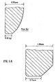
- the piercing end 14 of the rivet comprises an annular piercing edge 16 that defines a flat surface extending in a plane substantially parallel to that occupied by the upper surface 15 of the head and a radially inboard conical taper 17 that extends inwardly to meet with the bore 13.
- the taper has an included angle of 90° that forms a transition between the flat surface and the bore 13 in the shank 12.
- the thickness of the flat surface on each side of the section is L1
- the length of the taper is L2
- the overall thickness of the shank wall is L3.
- the inside surface 18 of the shank that defines the bore is of substantially constant diameter throughout most of its length save for its base 19.
- the base 19 is very slightly conical and there is an arcuate transition of radius R2 between the periphery of the base 19 and the inside surface of the shank 18 as best seen in figure 6 .
- FIG 5A the piercing end of the rivet is shown alongside that of a commercially available rivet (depicted on the left) of the corresponding size and of the kind described in US 6,385,843 .
- the piercing edge 16 is significantly longer in the present rivet compared to the prior art rivet and the conical taper 17 is provided by a discrete surface rather than a curved transition into the bore.
- the exact form of the piercing edge 16 and conical taper 17 may vary.
- the piercing edge 16 may be in the form of a surface that is not flat but is rather arcuate or convex.
- a suitable radius may be provided at the intersections between the piercing edge 16 and the outside surface of the shank and/or the conical taper 17.
- the surface defined by the piercing edge 16 need not necessarily be disposed in a plane perpendicular to the central axis of the rivet but may be inclined at an angle in the region of up to 10° to that plane.
- the rivet has an upper solid portion defined by a distance W between the top surface 15 of the rivet head 11 and the base 19 of the central bore 13 of the shank (see figure 5 ), and a hollow portion provided by the bore.
- transition radius R1 of the lower part of the head is 1.0mm and the transition radius R2 at the base of the bore is 0.4mm.
- the transition radius R1 does not extend over a full 90° arc.
- the alternative rivet design of figures 7 and 8 differs only in the shape of the head.
- the head 20 in larger and is designed to stand proud from the workpiece into which it is inserted.
- the upper surface 21 of the head has a planar central portion and an arcuately tapered periphery 22.
- examples of the measurements L and W are shown in the table below: "L" "W” 5 3.5 6 4.0 7 4.0 8 4.5 9 5.5 10 6.5 11 7.5 12 8.5 14 10.5
- transition radius R1 at the head is 1.0mm and the transition radius R2 in the bore is 0.4mm.
- the thickness or the cross-sectional area of the shank in the region where it is hollow is greater for the rivet of the present invention than compared to that of a conventional self-piercing rivet. This provides an improvement in the column strength of the rivet shank providing greater resistance to the onset of compression or buckling.
- the precise thickness needs to be carefully controlled in order to avoid both insufficient and excess flaring of the shank and thereby ensure that the rivet is capable of forming good quality joints in high strength steel.
- the length of the flat surface L1 should be relatively short in comparison to the thickness of the shank in order for the rivet to be suitable for riveting high strength steel or thick stack steel a ratio of L1:L3 in the range 0.33 to 0.66 produces the best results.
- the ratio L1:L3 is 0.5 or 0.6.
- the shank of the rivet of figures 4 to 6 or figures 7 and 8 has an outside diameter Do of 5.5mm and an inside diameter Di of 2.9mm. This results in the difference between the diameters (Do minus Di) being 2.6mm.
- the ratio of this difference (i.e. twice the shank thickness) to the outside diameter is therefore 0.473. This compares to a ratio in the range of 0.340 to 0.437 for conventional rivet designs of a comparable size.
- the cross-sectional area of the shank in this region is 17.15mm 2 .
- a comparable conventional rivet has a cross-sectional area of no larger than 14.2mm 2 .
- the ratio of the shank thickness to outside diameter can be increased to 0.517 without impairing the ability of the shank to flare sufficiently.
- the cross-sectional area is greater than 16.5mm 2 , and may be up to 22.0mm 2 .
- the ratio of the cross-sectional area of the shank (in the hollow region) to the outside diameter of the rivet is 3.1:1 which compares to a ratio of 2.4:1 to 2.8:1 in prior art rivets of this kind.
- the head of the rivet has a diameter of 7.75mm and this ensures that the rivet is small enough to be used with existing rivet setting and feeding equipment and is consistent with design guidelines for the space required for the rivet and the access of the application tooling.
- the ratio of the diameter of the rivet head to the outside diameter of the shank is 1.4:1. This compares to a ratio of 1.5:1 for conventional self-piercing rivets.
- the rivet is preferably made from a medium carbon manganese-boron steel e.g. conforming to British Standard BS EN 10263 that has been heat treated in a conventional manner to achieve a hardness of at least 350 Hv.
- a medium carbon manganese-boron steel e.g. conforming to British Standard BS EN 10263 that has been heat treated in a conventional manner to achieve a hardness of at least 350 Hv.
- FIG 9 shows the rivet 10 of figures 4 to 6 held in the nose 30 of a rivet setter by centring elements 31 (e.g. a plurality of spring centring balls) ready for insertion into overlapping sheets 32, at least one of which is material of the type mentioned need to clarify this statement.
- the rivet setter comprises a clamping ring 33 and a punch 34 by which the rivet is inserted.
- the rivet setter may be hydraulically or electrically actuated.
- the sheet material 32 is supported over a die 35 opposite the punch and may first be clamped before the punch inserts the rivet in accordance with the method described in our US patent No. 5,752,305 . As the rivet is inserted the material deforms into a suitably shaped cavity 36 in the die.
- Figure 10 shows a completed joint in which the rivet of figure 7 and 8 has been inserted into overlapping sheets of high strength steel of relatively low ductility with an ultimate tensile strength (UTS) of approx. 600 Mpa, both sheets having a thickness of 2.6mm.
- UTS ultimate tensile strength
- An insertion force of 47kN was used. It can be seen that the deformation of the rivet shank is substantially uniform around the rivet and there is no buckling. The degree of flare of the shank and the undercut in the bottom sheet is sufficient to provide satisfactory mechanical properties of the joints. A visual inspection will show that there is no significant separation of the sheets from one another and no clearance between the outside of the shank and the sheets which indicates that the joint will exhibit satisfactory dynamic performance.
- the thicker shank of the rivet in comparison to its outside diameter improves the column strength such that the rivet can withstand the high forces required to pierce and form the joint in the high strength steel.
- the increased thickness must be selected carefully in relation to the outside diameter as it is a factor in ensuring that the rivet shank has the capacity to flare outwardly during insertion and to provide sufficient interlock with the sheets when upset in a suitable die. It has been realised that for high strength steels or thick stack joints adequate joint strength is achieved with a lower degree of flare than would be necessary for conventional riveted joints.
- the thicker shank and the depth W are selected to ensure that the rivet is not compressed in height significantly during the rivet insertion operation and will be discernable from an inspection of figure 10 .
- the radii on the outside and inside of the shank are designed to withstand the initiation of cracking and are greater than for conventional rivets.
- the rivet is particularly suitable for joining high strength steels having an ultimate tensile strength in the range 200 to 1400 MPa, the total thickness of the stack being in the range 2.5 to 7mm and no sheet being greater than 4mm in thickness. In some tests successful joints have been achieved in a stack thickness of 8mm.
- the joint may comprise such a rivet used to join a single sheet of this type to any other type of sheet material suitable for riveting, in which case the total thickness of the sheet stack is in the range 4 to 18mm.
- the rivet is suitable for joining thick stacks of more conventional sheet materials in which the total thickness of the stack is between 4mm and 18mm.
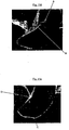
- the prior art rivet has a shank with an outside diameter of 5.3mm and an inside diameter of 3.2mm giving a ratio of shank thickness to outside diameter of 0.4:1. It can be seen that the rivet has insufficient column strength resulting in collapse and fracture (indicated by arrows A) in the finished joint. Moreover, premature and/or excessive flaring of the end of the shank has caused gaps (one example indicated by arrow B) to appear between the shank and the sheets.
- the prior art rivet (Henrob rivet type P50746) has a shank with an outside diameter of 5.1mm and an inside diameter of 2.9mm. The ratio of the thickness of the shank to the outside diameter is 0.43.
- the shank being thicker than that of the rivet of figure 11A , it is clear from the finished joint that it has insufficient column strength that has lead to partial collapse and fracture (see arrow C). Again sheet to shank gaps are apparent (one example indicated by arrow D) as a result of premature or excessive flaring.
- a rivet embodying the present invention has a shank with an outside diameter of 5.5mm, an inside diameter of 2.9mm (giving a shank thickness to outside diameter ratio of 0.47) and a tip geometry as depicted in figure 5A .
- the rivet has sufficient column strength to pierce the top sheet and penetrate into the bottom sheet without collapse.
- the geometry is such that premature or excessive flaring of the end of the shank is prevented as evidenced by the lack of fracturing, but the ductility is sufficient to allow interlock with the lower sheet.
- the geometry of the rivet ensures that the shank only starts to flare once it has penetrated the upper sheet such that there are no significant gaps between the sheets and the shank. The final joint has sufficient interlock between the rivet and the sheets to provide satisfactory mechanical properties.
- the rivet of the present invention is designed to tolerate the variations in strength characteristics in steel of a given grade in industry.
- rivet of the present invention may be used to join both thin and thick sheet combinations.
- the rivet may be used to join more than two sheets, or may be adapted to include a threaded stud formed on its head for insertion into a single sheet
Landscapes
- Engineering & Computer Science (AREA)
- General Engineering & Computer Science (AREA)
- Mechanical Engineering (AREA)
- Insertion Pins And Rivets (AREA)
- Connection Of Plates (AREA)
- Steroid Compounds (AREA)
- Organic Low-Molecular-Weight Compounds And Preparation Thereof (AREA)
- Laminated Bodies (AREA)
Claims (12)
- Selbststanzniet (10), der einen im Wesentlichen zylindrischen Schaft (12), der einen Außendurchmesser (Do) und einen Kopf (11) hat, umfasst, wobei der Schaft eine mittige Blindbohrung (13), die einen Innendurchmesser (Di) definiert, und ein ringförmiges Stanzende (14), das mit Zwischenraum zu dem Kopf (11) angeordnet ist, hat, wobei das Verhältnis der Differenz zwischen dem Außen- (Do) und dem Innendurchmesser (Di) des Schafts in dem Bereich um die Bohrung zu dem Außendurchmesser (Do) des Schafts in dem Bereich von 0,47 bis 0,52 liegt, wobei das Verhältnis der wirksamen Länge des Niets zu der Tiefe der Bohrung in dem Bereich von 1,56 bis 2,4 liegt, wobei das ringförmige Stanzende einen ersten Abschnitt umfasst, der in Radialrichtung außerhalb von einem zweiten Abschnitt liegt, wobei der zweite Abschnitt eine konische Verjüngung zwischen dem ersten Abschnitt und der Bohrung ist, wobei der erste Abschnitt eine Fläche definiert, die im Allgemeinen derart angeordnet ist, dass sie in einem Winkel zwischen 0° und 10° zu der Senkrechten zu der Mittelachse geneigt ist, und wobei die Querschnittsfläche des Schafts (12) in dem Bereich um die Bohrung (13) größer ist als 16,5 mm2, dadurch gekennzeichnet, dass:der Niet zum Verbinden von hochfestem Stahlblech verwendet wird, aus "Fastener Grade"-Stahl besteht und auf eine Härte von mindestens 350 Hv wärmebehandelt wird, der Schaft (12) des Niets (10) einen Außendurchmesser (Do) von 5,5 mm hat, und das Verhältnis des Durchmessers des Kopfs zu dem Außendurchmesser des Schafts in dem Bereich von 1,35 bis 1,47:1 liegt.
- Selbststanzniet nach Anspruch 1, wobei das Verhältnis der Querschnittsfläche des Schafts in dem Bereich um die Bohrung zu dem Außendurchmesser des Schafts in dem Bereich von 3,0:1 bis 3,6:1 liegt.
- Selbststanzniet nach einem der vorhergehenden Ansprüche, wobei der erste Abschnitt eine Fläche definiert, die im Allgemeinen derart angeordnet ist, dass sie sich im Wesentlichen senkrecht zu einer Mittelache des Niets erstreckt.
- Selbststanzniet nach einem der vorhergehenden Ansprüche, wobei die durch den ersten Abschnitt definierte Fläche im Wesentlichen flach oder bogenförmig ist.
- Selbststanzniet nach einem der vorhergehenden Ansprüche, wobei der erste Abschnitt in einem flacheren Winkel als der zweite Abschnitt zu einer Mittelachse des Niets geneigt ist.
- Selbststanzniet nach einem der vorhergehenden Ansprüche, wobei das Verhältnis der Länge des ersten Abschnitts zu der Dicke des Schafts in dem Bereich von 0,33 bis 0,66:1 liegt.
- Selbststanzniet nach einem der vorhergehenden Ansprüche, wobei der Kopf einen oberen Abschnitt und einen Übergangsbereich, der zwischen dem oberen Abschnitt und dem Schaft definiert ist, hat, wobei der Übergangsbereich einen Krümmungsradius in dem Bereich von 0,8 mm bis 1,2 mm hat.
- Selbststanzniet nach einem der vorhergehenden Ansprüche, wobei die Bohrung durch eine im Wesentlichen zylindrische Fläche, die konzentrisch mit der Außenfläche des Schafts ist, und eine Grundfläche definiert wird, wobei es einen Übergangsbereich zwischen der zylindrischen Fläche und dem Umfang der Grundfläche gibt, wobei der Übergangsbereich einen Krümmungsradius hat, der größer ist als 0,3 mm.
- Verfahren zum Herstellen einer Verbindung zwischen wenigstens einem hochfesten Stahlblech, das eine spezifische Zugfestigkeit (Ultimate Tensile Strength - UTS) in dem Bereich von 200 bis 1400 Mpa hat, und einem Blech aus einem anderen Material, wobei die kombinierte Dicke der Bleche in dem Bereich von 4 mm bis 18 mm liegt, unter Verwendung eines Selbststanzniets (10) aus "Fastener Grade"-Stahl, der auf eine Härte von mindestens 350 Hv wärmbehandelt wurde, umfassend die folgenden Schritte: Anordnen des Blechmaterials über einer Matrize, Bereitstellen eines Niets (10), der einen im Wesentlichen zylindrischen Schaft (12) und einen Kopf (11) hat, wobei der Schaft (12) eine mittige Blindbohrung (13) und ein ringförmiges Stanzende (14), das mit Zwischenraum zu dem Kopf angeordnet ist, hat, Anordnen eines Niets über dem Blechmaterial in einer Position gegenüber der Matrize, Verwenden eines Stempels, um den Niet (10) zu setzen und ihn in das Blechmaterial zu zwingen derart, dass er die obere Fläche desselben durchstanzt, und derart, dass sich der Schaft (12) nach außen hin verformt, um mit dem Material ineinanderzugreifen, aber ohne Durchdringen bis zu der Matrizenseite des Materials, dadurch gekennzeichnet, dass der bereitgestellte Niet ein Verhältnis der Differenz zwischen dem Außen- (Do) und Innendurchmesser (Di) des Schafts in dem Bereich um die Bohrung zu dem Außendurchmesser (Do) des Schafts in dem Bereich von 0,47 bis 0,52 hat, das Verhältnis der wirksamen Länge des Niets zu der Tiefe der Bohrung in dem Bereich von 1,56 bis 2,4 liegt, das ringförmige Stanzende einen ersten Abschnitt umfasst, der in Radialrichtung außerhalb von einem zweiten Abschnitt liegt, der zweite Abschnitt eine konische Verjüngung zwischen dem ersten Abschnitt und der Bohrung ist, und der erste Abschnitt eine Fläche definiert, die im Allgemeinen derart angeordnet ist, dass sie in einem Winkel zwischen 0° und 10° zu der Senkrechten zu der Mittelachse geneigt ist, derart, dass der Schaft des Niets genügend Säulenstärke aufweist, um das Obere des Materials ohne Ausbeulung zu durchstanzen und sich während des Einführens ohne Reißen oder Kracken nach außen hin ausweitet.
- Verfahren zum Verbinden eines Stapels von hochfesten Stahlblechen, die eine spezifische Zugfestigkeit (Ultimate Tensile Strength - UTS) in dem Bereich von 200 bis 1400 MPa haben, wobei die Gesamtdicke des Stapels in dem Bereich von 2,5 mm bis 7 mm liegt und kein Blech eine Dicke von mehr als 4 mm aufweist, unter Verwendung eines Selbststanzniets (10) aus "Fastener Grade"-Stahl, der auf eine Härte von mindestens 350 Hv wärmbehandelt wurde, umfassend die folgenden Schritte: Anordnen des Blechmaterials über einer Matrize, Bereitstellen eines Niets (10), der einen im Wesentlichen zylindrischen Schaft (12) und einen Kopf (11) hat, wobei der Schaft (12) eine mittige Blindbohrung (13) und ein ringförmiges Stanzende (14), das mit Zwischenraum zu dem Kopf angeordnet ist, hat, Anordnen eines Niets über dem Blechmaterial in einer Position gegenüber der Matrize, Verwenden eines Stempels, um den Niet (10) zu setzen und ihn in das Blechmaterial zu zwingen derart, dass er die obere Fläche desselben durchstanzt, und derart, dass sich der Schaft (12) nach außen hin verformt, um mit dem Material ineinanderzugreifen, aber ohne Durchdringen bis zu der Matrizenseite des Materials, dadurch gekennzeichnet, dass der bereitgestellte Niet ein Verhältnis der Differenz zwischen dem Außen- (Do) und Innendurchmesser (Di) des Schafts in dem Bereich um die Bohrung zu dem Außendurchmesser (Do) des Schafts in dem Bereich von 0,47 bis 0,52 hat, das Verhältnis der wirksamen Länge des Niets zu der Tiefe der Bohrung in dem Bereich von 1,56 bis 2,4 liegt, das ringförmige Stanzende einen ersten Abschnitt umfasst, der in Radialrichtung außerhalb von einem zweiten Abschnitt liegt, der zweite Abschnitt eine konische Verjüngung zwischen dem ersten Abschnitt und der Bohrung ist, und der erste Abschnitt eine Fläche definiert, die im Allgemeinen derart angeordnet ist, dass sie in einem Winkel zwischen 0° und 10° zu der Senkrechten zu der Mittelachse geneigt ist, derart, dass der Schaft des Niets genügend Säulenstärke aufweist, um den oberen Teil des Materials ohne Ausbeulung zu durchstanzen und sich während des Einführens ohne Reißen oder Kracken nach außen hin ausweitet.
- Verfahren nach Anspruch 9 oder 10, das dazu verwendet wird, mehrere Bleche eines solchen Materials zu verbinden, wobei der Niet in das oberste Blech eindringt und sich verformt, um so alle Bleche miteinander zu verbinden, aber zumindest in das unterste Blech nicht eindringt.
- Selbststanzniet-Einsetzsystem, das einen Stempel zum Ausüben einer Einsetzkraft auf einen Niet, eine Matrize, in die das genietete Material verformt wird, und einen Niet (10) nach einem der Ansprüche 1 bis 8 umfasst.
Applications Claiming Priority (2)
| Application Number | Priority Date | Filing Date | Title |
|---|---|---|---|
| GBGB0609580.6A GB0609580D0 (en) | 2006-05-13 | 2006-05-13 | Self-piercing riveting |
| PCT/GB2007/001725 WO2007132194A1 (en) | 2006-05-13 | 2007-05-10 | Self-piercing riveting |
Publications (3)
| Publication Number | Publication Date |
|---|---|
| EP2024651A1 EP2024651A1 (de) | 2009-02-18 |
| EP2024651B1 EP2024651B1 (de) | 2009-09-02 |
| EP2024651B2 true EP2024651B2 (de) | 2014-03-05 |
Family
ID=36637497
Family Applications (1)
| Application Number | Title | Priority Date | Filing Date |
|---|---|---|---|
| EP07732751.8A Active EP2024651B2 (de) | 2006-05-13 | 2007-05-10 | Selbststanznietung |
Country Status (7)
| Country | Link |
|---|---|
| US (4) | US8070406B2 (de) |
| EP (1) | EP2024651B2 (de) |
| JP (3) | JP5357753B2 (de) |
| AT (1) | ATE441783T1 (de) |
| DE (1) | DE602007002300D1 (de) |
| GB (1) | GB0609580D0 (de) |
| WO (1) | WO2007132194A1 (de) |
Cited By (2)
| Publication number | Priority date | Publication date | Assignee | Title |
|---|---|---|---|---|
| DE102019102380A1 (de) | 2019-01-30 | 2020-07-30 | Böllhoff Verbindungstechnik GmbH | Vollstanzniet, eine Stanznietverbindung aus mindestens zwei Bauteilen mithilfe des Vollstanzniets sowie ein Verfahren zum Verbinden der Bauteile mit dem Vollstanzniet |
| DE102019102383A1 (de) | 2019-01-30 | 2020-07-30 | Böllhoff Verbindungstechnik GmbH | Halbhohlstanzniet, eine Stanznietverbindung aus mindestens zwei Bauteilen mithilfe des Halbhohlstanzniets sowie ein Verfahren zum Verbinden der Bauteile mit dem Halbhohlstanzniet |
Families Citing this family (38)
| Publication number | Priority date | Publication date | Assignee | Title |
|---|---|---|---|---|
| GB0609580D0 (en) * | 2006-05-13 | 2006-06-21 | Henrob Ltd | Self-piercing riveting |
| US20100018040A1 (en) * | 2008-07-27 | 2010-01-28 | Bradley Edward Joseph | Crimping tool adapter for alignment and installation of coaxial cable connector nut rotation aid |
| DE102009039936A1 (de) | 2009-08-24 | 2011-04-07 | Newfrey Llc, Newark | Stanzniet, Verfahren zum Hersteller einer Stanznietverbindung und Werkstückanordnung |
| DE102009050342B4 (de) | 2009-10-22 | 2011-10-13 | Audi Ag | Halbhohlstanzniet |
| GB201019021D0 (en) | 2010-11-11 | 2010-12-22 | Henrob Ltd | A rivet |
| CN103987510B (zh) * | 2011-12-20 | 2015-11-25 | 丰田自动车株式会社 | 构件的连接方法和连接构造 |
| DE102012003819A1 (de) | 2012-02-27 | 2013-08-29 | Profil Verbindungstechnik Gmbh & Co. Kg | Funktionselement zur fluiddichten Anbringung an ein Blechteil, Zusammenbauteil und Verfahren |
| DE112013001349T5 (de) * | 2012-03-09 | 2014-11-20 | Firestone Industrial Products Company, Llc | Gasfeder- und Komponentenbaugruppe sowie Zusammenbauverfahren |
| US10005120B2 (en) | 2012-07-16 | 2018-06-26 | Henrob Limited | Method for forming a joint using a self-piercing rivet |
| DE202013012734U1 (de) | 2013-12-11 | 2018-12-13 | Newfrey Llc | Stanzniet sowie Stanznietverbindung |
| DE102014201976A1 (de) | 2014-02-04 | 2015-08-06 | Böllhoff Verbindungstechnik GmbH | Stanzniet |
| US20150290914A1 (en) | 2014-04-10 | 2015-10-15 | Ford Global Technologies, Llc | Process For Joining Carbon Fiber Composite Materials Using Self-Piercing Rivets |
| DE102015101950A1 (de) * | 2015-02-11 | 2016-08-11 | Newfrey Llc | Stanzniet und Verfahren zum Herstellen einer Stanznietverbindung |
| GB201508297D0 (en) | 2015-05-14 | 2015-06-24 | Henrob Ltd | Method of manufacturing self-pierce rivets |
| US9957584B2 (en) * | 2015-08-10 | 2018-05-01 | Ford Motor Company | Method and system for enhancing rivetability |
| KR101755483B1 (ko) * | 2015-09-10 | 2017-07-10 | 현대자동차 주식회사 | 이종소재 접합 구조체 |
| DE102015118888A1 (de) * | 2015-11-04 | 2017-05-04 | Böllhoff Verbindungstechnik GmbH | Halbhohlstanzniet für Dünnblechverbindungen, Verfahren zu seiner Herstellung und Verfahren zur Herstellung einer Verbindung |
| KR102710669B1 (ko) | 2016-02-03 | 2024-09-27 | 유티카 엔터프라이지스 인코포레이티드 | 첨단 고강도 스틸을 기계식으로 접합하기 위한 장치 및 방법 |
| DE202016102528U1 (de) | 2016-05-11 | 2017-08-16 | Newfrey Llc | Stanzniet sowie Stanznietverbindung |
| US10669599B2 (en) | 2016-09-16 | 2020-06-02 | Colorado School Of Mines | Decarburized self-piercing rivet |
| WO2018160959A1 (en) | 2017-03-03 | 2018-09-07 | Utica Enterprises, Inc. | Apparatus and method for securing a clinch nut to a sheet of advanced high strength steel and resultant assembly |
| US10385900B2 (en) | 2017-03-24 | 2019-08-20 | Ford Global Technologies, Llc | Reduced diameter head rivet |
| GB201812641D0 (en) | 2018-08-03 | 2018-09-19 | Henrob Ltd | Riveting method |
| EP3626982B1 (de) * | 2018-09-21 | 2022-02-16 | Newfrey LLC | Stanzniet |
| JP7182989B2 (ja) * | 2018-10-12 | 2022-12-05 | 株式会社アーレスティ | 接合体の製造方法および板状部材の品質管理方法 |
| DE102019204826A1 (de) * | 2019-04-04 | 2020-10-08 | Audi Ag | Stanznietverbindung sowie Stanzniet |
| EP3748171B1 (de) * | 2019-06-05 | 2023-06-21 | Newfrey LLC | Stanzniet |
| DE102020102982A1 (de) * | 2020-02-05 | 2021-08-05 | Böllhoff Verbindungstechnik GmbH | Fügeelement, Verbindungsstruktur mit dem Fügeelement, Herstellungsverfahren des Fügeelements und entsprechendes Verbindungsverfahren |
| US11460059B1 (en) * | 2020-03-06 | 2022-10-04 | Battelle Memorial Institute | Riveted assemblies and methods for riveting components |
| DE102020111696A1 (de) * | 2020-04-29 | 2021-11-04 | Profil Verbindungstechnik Gmbh & Co. Kg | Funktionselement |
| DE102021115577B3 (de) * | 2021-06-16 | 2022-12-01 | Audi Aktiengesellschaft | Nietverbindung |
| CN113680951B (zh) * | 2021-09-24 | 2022-07-15 | 上海交通大学 | 双向机械互锁与固相连接复合的点连接方法 |
| CN114160743B (zh) * | 2021-11-22 | 2024-10-25 | 苏州雷力紧固技术有限责任公司 | 一种自冲铆连接装置及其铆接方法 |
| CN114227333B (zh) * | 2021-12-31 | 2024-05-03 | 兴化日成金属制品有限公司 | 一种可夹持四方产品的液压卡盘 |
| CN114749568A (zh) * | 2022-04-24 | 2022-07-15 | 广州连捷精密技术有限公司 | 自动铆压模具 |
| CN116652434B (zh) * | 2023-05-30 | 2026-01-30 | 浙江吉利控股集团有限公司 | 焊接接头及其制造方法 |
| EP4542062A1 (de) * | 2023-10-18 | 2025-04-23 | Newfrey LLC | Halbhohler selbststanzender niet und verbindungsverfahren damit |
| EP4663961A1 (de) * | 2024-06-11 | 2025-12-17 | Newfrey LLC | Selbststanzender niet für hochfeste aluminiumanwendungen |
Citations (1)
| Publication number | Priority date | Publication date | Assignee | Title |
|---|---|---|---|---|
| JPH09317730A (ja) † | 1996-05-29 | 1997-12-09 | Fukui Byora Kk | 打込リベット |
Family Cites Families (25)
| Publication number | Priority date | Publication date | Assignee | Title |
|---|---|---|---|---|
| GB9022772D0 (en) | 1990-10-19 | 1990-12-05 | Ariel Ind Plc | Self piercing rivet |
| DE4333052C2 (de) | 1993-09-29 | 2002-01-24 | Audi Ag | Selbststanzende Befestigungsvorrichtung |
| JP3382722B2 (ja) * | 1994-06-22 | 2003-03-04 | 大和製罐株式会社 | チューブラリベット |
| JP3958883B2 (ja) | 1999-01-14 | 2007-08-15 | 新日本製鐵株式会社 | 疲労特性に優れた高強度鋼板の接合方法 |
| DE50000124D1 (de) * | 1999-01-26 | 2002-04-25 | Bergner Verbindungstechnik Gmb | Stanzniet |
| US6325584B1 (en) * | 1999-03-30 | 2001-12-04 | Richard Bergner Gmbh | Self-piercing rivet |
| JP2001099113A (ja) * | 1999-09-27 | 2001-04-10 | Nippon Steel Corp | めっき鋼板、塗装鋼板の機械的接合方法および接合用材料 |
| WO2001030516A1 (en) * | 1999-10-26 | 2001-05-03 | Toyota Jidosha Kabushiki Kaisha | Rivet, riveted joint structure, riveting apparatus, and riveting method |
| JP3745175B2 (ja) * | 1999-10-26 | 2006-02-15 | トヨタ自動車株式会社 | リベットによる結合構造及びリベットによる結合方法 |
| DE50202025D1 (de) * | 2001-02-02 | 2005-02-24 | Bergner Verbindungstechnik Gmb | Stanznietverbindung und Halbhohlstanzniet |
| DE10147076A1 (de) * | 2001-09-25 | 2003-04-17 | Profil Verbindungstechnik Gmbh | Befestigungselement |
| JP2003191041A (ja) | 2001-12-25 | 2003-07-08 | Nippon Pop Rivets & Fasteners Ltd | 自動穿孔リベット締結装置及びシステム |
| US7284319B2 (en) | 2002-02-08 | 2007-10-23 | Newfrey Llc | Self-piercing rivet setting die and apparatus |
| JP3830421B2 (ja) | 2002-05-28 | 2006-10-04 | 株式会社神戸製鋼所 | 自己穿孔型リベットによるアルミニウム又はアルミニウム合金材の接合方法 |
| JP2004060855A (ja) * | 2002-07-31 | 2004-02-26 | Nippon Pop Rivets & Fasteners Ltd | セルフピアシングリベット |
| JP2004345490A (ja) | 2003-05-22 | 2004-12-09 | Chuo Motor Wheel Co Ltd | 自動車用ホイール |
| JP4389510B2 (ja) | 2003-07-16 | 2009-12-24 | 日産自動車株式会社 | 狭域無線通信用車載端末 |
| DE20319610U1 (de) | 2003-12-17 | 2004-03-04 | Böllhoff GmbH | Stanzniet für hochfeste Bleche |
| JP4466100B2 (ja) | 2004-02-05 | 2010-05-26 | 日産自動車株式会社 | ハイブリッド車体構造及びその製造方法 |
| JP4669706B2 (ja) | 2005-02-15 | 2011-04-13 | 株式会社ロブテックス | 自己穿孔型リベット及びこれによる板材の締結構造 |
| DE202005012677U1 (de) * | 2005-08-09 | 2005-10-13 | Textron Verbindungstechnik Gmbh & Co. Ohg | Selbststanzendes rotationsymmetrisches Niet |
| DE102005052360B4 (de) * | 2005-11-02 | 2008-07-24 | Böllhoff Verbindungstechnik GmbH | Stanzniet |
| GB0609580D0 (en) * | 2006-05-13 | 2006-06-21 | Henrob Ltd | Self-piercing riveting |
| DE102006028537B3 (de) * | 2006-06-21 | 2007-05-10 | Singh, Sumanjit, Dr. | Stanzniet und Matrize |
| DE202006013981U1 (de) * | 2006-06-21 | 2006-11-16 | Singh, Sumanjit, Dr. | Stanzniet und Matrize |
-
2006
- 2006-05-13 GB GBGB0609580.6A patent/GB0609580D0/en not_active Ceased
-
2007
- 2007-05-10 WO PCT/GB2007/001725 patent/WO2007132194A1/en not_active Ceased
- 2007-05-10 EP EP07732751.8A patent/EP2024651B2/de active Active
- 2007-05-10 US US12/300,630 patent/US8070406B2/en active Active
- 2007-05-10 DE DE602007002300T patent/DE602007002300D1/de active Active
- 2007-05-10 JP JP2009510525A patent/JP5357753B2/ja active Active
- 2007-05-10 AT AT07732751T patent/ATE441783T1/de not_active IP Right Cessation
-
2011
- 2011-11-17 US US13/298,466 patent/US8898880B2/en active Active
- 2011-11-17 US US13/298,486 patent/US8328484B2/en active Active
-
2013
- 2013-06-12 JP JP2013123866A patent/JP5972225B2/ja active Active
-
2014
- 2014-10-31 US US14/529,612 patent/US9364885B2/en active Active
-
2015
- 2015-05-07 JP JP2015094638A patent/JP6159753B2/ja active Active
Patent Citations (1)
| Publication number | Priority date | Publication date | Assignee | Title |
|---|---|---|---|---|
| JPH09317730A (ja) † | 1996-05-29 | 1997-12-09 | Fukui Byora Kk | 打込リベット |
Cited By (4)
| Publication number | Priority date | Publication date | Assignee | Title |
|---|---|---|---|---|
| DE102019102380A1 (de) | 2019-01-30 | 2020-07-30 | Böllhoff Verbindungstechnik GmbH | Vollstanzniet, eine Stanznietverbindung aus mindestens zwei Bauteilen mithilfe des Vollstanzniets sowie ein Verfahren zum Verbinden der Bauteile mit dem Vollstanzniet |
| DE102019102383A1 (de) | 2019-01-30 | 2020-07-30 | Böllhoff Verbindungstechnik GmbH | Halbhohlstanzniet, eine Stanznietverbindung aus mindestens zwei Bauteilen mithilfe des Halbhohlstanzniets sowie ein Verfahren zum Verbinden der Bauteile mit dem Halbhohlstanzniet |
| EP3690260A1 (de) | 2019-01-30 | 2020-08-05 | Böllhoff Verbindungstechnik GmbH | Halbhohlstanzniet, eine stanznietverbindung aus mindestens zwei bauteilen mithilfe des halbhohlstanzniets sowie ein verfahren zum verbinden der bauteile mit dem halbhohlstanzniet |
| US11686336B2 (en) | 2019-01-30 | 2023-06-27 | Böllhoff Verbindungstechnik GmbH | Semi-hollow punch rivet, a punch rivet joint of at least two components by means of a semi-hollow punch rivet as well as a method for connecting the components with the semi-hollow punch rivet |
Also Published As
| Publication number | Publication date |
|---|---|
| US8328484B2 (en) | 2012-12-11 |
| US20120090158A1 (en) | 2012-04-19 |
| DE602007002300D1 (de) | 2009-10-15 |
| US8070406B2 (en) | 2011-12-06 |
| JP5357753B2 (ja) | 2013-12-04 |
| EP2024651B1 (de) | 2009-09-02 |
| JP6159753B2 (ja) | 2017-07-05 |
| GB0609580D0 (en) | 2006-06-21 |
| US8898880B2 (en) | 2014-12-02 |
| EP2024651A1 (de) | 2009-02-18 |
| ATE441783T1 (de) | 2009-09-15 |
| WO2007132194A1 (en) | 2007-11-22 |
| US9364885B2 (en) | 2016-06-14 |
| JP2015166111A (ja) | 2015-09-24 |
| US20120060338A1 (en) | 2012-03-15 |
| US20090116934A1 (en) | 2009-05-07 |
| JP2009537757A (ja) | 2009-10-29 |
| JP2013215807A (ja) | 2013-10-24 |
| US20150239034A1 (en) | 2015-08-27 |
| JP5972225B2 (ja) | 2016-08-17 |
Similar Documents
| Publication | Publication Date | Title |
|---|---|---|
| EP2024651B2 (de) | Selbststanznietung | |
| US9316243B2 (en) | Method for forming a joint in a stack of light metal alloy sheets | |
| US10751787B2 (en) | Method for forming a joint using a self-piercing rivet | |
| EP2470799B1 (de) | Stanzniete, verfahren zur herstellung einer stanznietenverbindung und werkstückanordnung | |
| US9091290B2 (en) | Punch rivet and die | |
| EP3256747B1 (de) | Stanzniet und verfahren zur herstellung einer stanznietverbindung | |
| EP3626982B1 (de) | Stanzniet | |
| JP2021532990A (ja) | リベット締めの方法 | |
| EP2606993A1 (de) | Matrize zum Setzen von Stanznieten | |
| EP3633215B1 (de) | Stanzniet | |
| US20250180055A1 (en) | Self-Piercing Rivet and Methods of Making and Using Same | |
| EP4663961A1 (de) | Selbststanzender niet für hochfeste aluminiumanwendungen | |
| EP4060197A1 (de) | Stanzniet und stanznietverbindung |
Legal Events
| Date | Code | Title | Description |
|---|---|---|---|
| PUAI | Public reference made under article 153(3) epc to a published international application that has entered the european phase |
Free format text: ORIGINAL CODE: 0009012 |
|
| 17P | Request for examination filed |
Effective date: 20081211 |
|
| AK | Designated contracting states |
Kind code of ref document: A1 Designated state(s): AT BE BG CH CY CZ DE DK EE ES FI FR GB GR HU IE IS IT LI LT LU LV MC MT NL PL PT RO SE SI SK TR |
|
| AX | Request for extension of the european patent |
Extension state: AL BA HR MK RS |
|
| GRAP | Despatch of communication of intention to grant a patent |
Free format text: ORIGINAL CODE: EPIDOSNIGR1 |
|
| GRAS | Grant fee paid |
Free format text: ORIGINAL CODE: EPIDOSNIGR3 |
|
| GRAA | (expected) grant |
Free format text: ORIGINAL CODE: 0009210 |
|
| AK | Designated contracting states |
Kind code of ref document: B1 Designated state(s): AT BE BG CH CY CZ DE DK EE ES FI FR GB GR HU IE IS IT LI LT LU LV MC MT NL PL PT RO SE SI SK TR |
|
| REG | Reference to a national code |
Ref country code: CH Ref legal event code: EP |
|
| REG | Reference to a national code |
Ref country code: IE Ref legal event code: FG4D |
|
| REF | Corresponds to: |
Ref document number: 602007002300 Country of ref document: DE Date of ref document: 20091015 Kind code of ref document: P |
|
| PG25 | Lapsed in a contracting state [announced via postgrant information from national office to epo] |
Ref country code: SE Free format text: LAPSE BECAUSE OF FAILURE TO SUBMIT A TRANSLATION OF THE DESCRIPTION OR TO PAY THE FEE WITHIN THE PRESCRIBED TIME-LIMIT Effective date: 20090902 Ref country code: LT Free format text: LAPSE BECAUSE OF FAILURE TO SUBMIT A TRANSLATION OF THE DESCRIPTION OR TO PAY THE FEE WITHIN THE PRESCRIBED TIME-LIMIT Effective date: 20090902 Ref country code: FI Free format text: LAPSE BECAUSE OF FAILURE TO SUBMIT A TRANSLATION OF THE DESCRIPTION OR TO PAY THE FEE WITHIN THE PRESCRIBED TIME-LIMIT Effective date: 20090902 |
|
| NLV1 | Nl: lapsed or annulled due to failure to fulfill the requirements of art. 29p and 29m of the patents act | ||
| LTIE | Lt: invalidation of european patent or patent extension |
Effective date: 20090902 |
|
| PG25 | Lapsed in a contracting state [announced via postgrant information from national office to epo] |
Ref country code: SI Free format text: LAPSE BECAUSE OF FAILURE TO SUBMIT A TRANSLATION OF THE DESCRIPTION OR TO PAY THE FEE WITHIN THE PRESCRIBED TIME-LIMIT Effective date: 20090902 Ref country code: LV Free format text: LAPSE BECAUSE OF FAILURE TO SUBMIT A TRANSLATION OF THE DESCRIPTION OR TO PAY THE FEE WITHIN THE PRESCRIBED TIME-LIMIT Effective date: 20090902 Ref country code: NL Free format text: LAPSE BECAUSE OF FAILURE TO SUBMIT A TRANSLATION OF THE DESCRIPTION OR TO PAY THE FEE WITHIN THE PRESCRIBED TIME-LIMIT Effective date: 20090902 Ref country code: PL Free format text: LAPSE BECAUSE OF FAILURE TO SUBMIT A TRANSLATION OF THE DESCRIPTION OR TO PAY THE FEE WITHIN THE PRESCRIBED TIME-LIMIT Effective date: 20090902 |
|
| PG25 | Lapsed in a contracting state [announced via postgrant information from national office to epo] |
Ref country code: CY Free format text: LAPSE BECAUSE OF FAILURE TO SUBMIT A TRANSLATION OF THE DESCRIPTION OR TO PAY THE FEE WITHIN THE PRESCRIBED TIME-LIMIT Effective date: 20090902 |
|
| PG25 | Lapsed in a contracting state [announced via postgrant information from national office to epo] |
Ref country code: IS Free format text: LAPSE BECAUSE OF FAILURE TO SUBMIT A TRANSLATION OF THE DESCRIPTION OR TO PAY THE FEE WITHIN THE PRESCRIBED TIME-LIMIT Effective date: 20100102 Ref country code: RO Free format text: LAPSE BECAUSE OF FAILURE TO SUBMIT A TRANSLATION OF THE DESCRIPTION OR TO PAY THE FEE WITHIN THE PRESCRIBED TIME-LIMIT Effective date: 20090902 Ref country code: PT Free format text: LAPSE BECAUSE OF FAILURE TO SUBMIT A TRANSLATION OF THE DESCRIPTION OR TO PAY THE FEE WITHIN THE PRESCRIBED TIME-LIMIT Effective date: 20100104 Ref country code: EE Free format text: LAPSE BECAUSE OF FAILURE TO SUBMIT A TRANSLATION OF THE DESCRIPTION OR TO PAY THE FEE WITHIN THE PRESCRIBED TIME-LIMIT Effective date: 20090902 Ref country code: ES Free format text: LAPSE BECAUSE OF FAILURE TO SUBMIT A TRANSLATION OF THE DESCRIPTION OR TO PAY THE FEE WITHIN THE PRESCRIBED TIME-LIMIT Effective date: 20091213 Ref country code: CZ Free format text: LAPSE BECAUSE OF FAILURE TO SUBMIT A TRANSLATION OF THE DESCRIPTION OR TO PAY THE FEE WITHIN THE PRESCRIBED TIME-LIMIT Effective date: 20090902 |
|
| PG25 | Lapsed in a contracting state [announced via postgrant information from national office to epo] |
Ref country code: SK Free format text: LAPSE BECAUSE OF FAILURE TO SUBMIT A TRANSLATION OF THE DESCRIPTION OR TO PAY THE FEE WITHIN THE PRESCRIBED TIME-LIMIT Effective date: 20090902 |
|
| PLBI | Opposition filed |
Free format text: ORIGINAL CODE: 0009260 |
|
| PG25 | Lapsed in a contracting state [announced via postgrant information from national office to epo] |
Ref country code: BE Free format text: LAPSE BECAUSE OF FAILURE TO SUBMIT A TRANSLATION OF THE DESCRIPTION OR TO PAY THE FEE WITHIN THE PRESCRIBED TIME-LIMIT Effective date: 20090902 Ref country code: AT Free format text: LAPSE BECAUSE OF FAILURE TO SUBMIT A TRANSLATION OF THE DESCRIPTION OR TO PAY THE FEE WITHIN THE PRESCRIBED TIME-LIMIT Effective date: 20090902 |
|
| PLAX | Notice of opposition and request to file observation + time limit sent |
Free format text: ORIGINAL CODE: EPIDOSNOBS2 |
|
| 26 | Opposition filed |
Opponent name: BOELLHOF VERBINDUNGSTECHNIK GMBH Effective date: 20100602 |
|
| PG25 | Lapsed in a contracting state [announced via postgrant information from national office to epo] |
Ref country code: DK Free format text: LAPSE BECAUSE OF FAILURE TO SUBMIT A TRANSLATION OF THE DESCRIPTION OR TO PAY THE FEE WITHIN THE PRESCRIBED TIME-LIMIT Effective date: 20090902 |
|
| PG25 | Lapsed in a contracting state [announced via postgrant information from national office to epo] |
Ref country code: GR Free format text: LAPSE BECAUSE OF FAILURE TO SUBMIT A TRANSLATION OF THE DESCRIPTION OR TO PAY THE FEE WITHIN THE PRESCRIBED TIME-LIMIT Effective date: 20091203 |
|
| PLAF | Information modified related to communication of a notice of opposition and request to file observations + time limit |
Free format text: ORIGINAL CODE: EPIDOSCOBS2 |
|
| PLAB | Opposition data, opponent's data or that of the opponent's representative modified |
Free format text: ORIGINAL CODE: 0009299OPPO |
|
| PG25 | Lapsed in a contracting state [announced via postgrant information from national office to epo] |
Ref country code: MC Free format text: LAPSE BECAUSE OF NON-PAYMENT OF DUE FEES Effective date: 20100531 |
|
| R26 | Opposition filed (corrected) |
Opponent name: BOELLHOF VERBINDUNGSTECHNIK GMBH Effective date: 20100602 |
|
| PLBB | Reply of patent proprietor to notice(s) of opposition received |
Free format text: ORIGINAL CODE: EPIDOSNOBS3 |
|
| REG | Reference to a national code |
Ref country code: FR Ref legal event code: ST Effective date: 20110131 |
|
| PG25 | Lapsed in a contracting state [announced via postgrant information from national office to epo] |
Ref country code: IT Free format text: LAPSE BECAUSE OF FAILURE TO SUBMIT A TRANSLATION OF THE DESCRIPTION OR TO PAY THE FEE WITHIN THE PRESCRIBED TIME-LIMIT Effective date: 20090902 |
|
| PG25 | Lapsed in a contracting state [announced via postgrant information from national office to epo] |
Ref country code: MT Free format text: LAPSE BECAUSE OF FAILURE TO SUBMIT A TRANSLATION OF THE DESCRIPTION OR TO PAY THE FEE WITHIN THE PRESCRIBED TIME-LIMIT Effective date: 20090902 Ref country code: IE Free format text: LAPSE BECAUSE OF NON-PAYMENT OF DUE FEES Effective date: 20100510 |
|
| PG25 | Lapsed in a contracting state [announced via postgrant information from national office to epo] |
Ref country code: FR Free format text: LAPSE BECAUSE OF NON-PAYMENT OF DUE FEES Effective date: 20100531 |
|
| REG | Reference to a national code |
Ref country code: CH Ref legal event code: PL |
|
| PG25 | Lapsed in a contracting state [announced via postgrant information from national office to epo] |
Ref country code: LI Free format text: LAPSE BECAUSE OF NON-PAYMENT OF DUE FEES Effective date: 20110531 Ref country code: CH Free format text: LAPSE BECAUSE OF NON-PAYMENT OF DUE FEES Effective date: 20110531 |
|
| PG25 | Lapsed in a contracting state [announced via postgrant information from national office to epo] |
Ref country code: BG Free format text: LAPSE BECAUSE OF FAILURE TO SUBMIT A TRANSLATION OF THE DESCRIPTION OR TO PAY THE FEE WITHIN THE PRESCRIBED TIME-LIMIT Effective date: 20090902 Ref country code: LU Free format text: LAPSE BECAUSE OF NON-PAYMENT OF DUE FEES Effective date: 20100510 Ref country code: HU Free format text: LAPSE BECAUSE OF FAILURE TO SUBMIT A TRANSLATION OF THE DESCRIPTION OR TO PAY THE FEE WITHIN THE PRESCRIBED TIME-LIMIT Effective date: 20100303 |
|
| PG25 | Lapsed in a contracting state [announced via postgrant information from national office to epo] |
Ref country code: TR Free format text: LAPSE BECAUSE OF FAILURE TO SUBMIT A TRANSLATION OF THE DESCRIPTION OR TO PAY THE FEE WITHIN THE PRESCRIBED TIME-LIMIT Effective date: 20090902 |
|
| PUAH | Patent maintained in amended form |
Free format text: ORIGINAL CODE: 0009272 |
|
| STAA | Information on the status of an ep patent application or granted ep patent |
Free format text: STATUS: PATENT MAINTAINED AS AMENDED |
|
| 27A | Patent maintained in amended form |
Effective date: 20140305 |
|
| AK | Designated contracting states |
Kind code of ref document: B2 Designated state(s): AT BE BG CH CY CZ DE DK EE ES FI FR GB GR HU IE IS IT LI LT LU LV MC MT NL PL PT RO SE SI SK TR |
|
| REG | Reference to a national code |
Ref country code: DE Ref legal event code: R102 Ref document number: 602007002300 Country of ref document: DE |
|
| REG | Reference to a national code |
Ref country code: DE Ref legal event code: R102 Ref document number: 602007002300 Country of ref document: DE Effective date: 20140305 |
|
| PG25 | Lapsed in a contracting state [announced via postgrant information from national office to epo] |
Ref country code: LV Free format text: LAPSE BECAUSE OF FAILURE TO SUBMIT A TRANSLATION OF THE DESCRIPTION OR TO PAY THE FEE WITHIN THE PRESCRIBED TIME-LIMIT Effective date: 20140305 |
|
| REG | Reference to a national code |
Ref country code: DE Ref legal event code: R081 Ref document number: 602007002300 Country of ref document: DE Owner name: ATLAS COPCO IAS UK LTD., DEESIDE, GB Free format text: FORMER OWNER: HENROB LTD., FLINTSHIRE, GB Ref country code: DE Ref legal event code: R082 Ref document number: 602007002300 Country of ref document: DE Representative=s name: MARKS & CLERK (LUXEMBOURG) LLP, LU Ref country code: DE Ref legal event code: R081 Ref document number: 602007002300 Country of ref document: DE Owner name: ATLAS COPCO IAS UK LIMITED, FLINT, GB Free format text: FORMER OWNER: HENROB LTD., FLINTSHIRE, GB |
|
| REG | Reference to a national code |
Ref country code: DE Ref legal event code: R081 Ref document number: 602007002300 Country of ref document: DE Owner name: ATLAS COPCO IAS UK LTD., DEESIDE, GB Free format text: FORMER OWNER: ATLAS COPCO IAS UK LIMITED, FLINT, FLINTSHIRE, GB |
|
| PGFP | Annual fee paid to national office [announced via postgrant information from national office to epo] |
Ref country code: DE Payment date: 20250529 Year of fee payment: 19 |
|
| PGFP | Annual fee paid to national office [announced via postgrant information from national office to epo] |
Ref country code: GB Payment date: 20250527 Year of fee payment: 19 |