EP2024719B1 - Sonde de temperature - Google Patents
Sonde de temperature Download PDFInfo
- Publication number
- EP2024719B1 EP2024719B1 EP07729895A EP07729895A EP2024719B1 EP 2024719 B1 EP2024719 B1 EP 2024719B1 EP 07729895 A EP07729895 A EP 07729895A EP 07729895 A EP07729895 A EP 07729895A EP 2024719 B1 EP2024719 B1 EP 2024719B1
- Authority
- EP
- European Patent Office
- Prior art keywords
- temperature
- sleeve
- individual
- segment
- probe
- Prior art date
- Legal status (The legal status is an assumption and is not a legal conclusion. Google has not performed a legal analysis and makes no representation as to the accuracy of the status listed.)
- Not-in-force
Links
- 239000000523 sample Substances 0.000 title claims abstract description 77
- 238000004891 communication Methods 0.000 claims abstract description 73
- 239000004020 conductor Substances 0.000 claims description 5
- 238000000034 method Methods 0.000 claims description 4
- 150000001875 compounds Chemical class 0.000 claims description 3
- 238000007789 sealing Methods 0.000 claims 1
- 230000008901 benefit Effects 0.000 description 9
- 238000005259 measurement Methods 0.000 description 8
- 238000011161 development Methods 0.000 description 4
- 238000009434 installation Methods 0.000 description 4
- 238000004382 potting Methods 0.000 description 4
- 229910001369 Brass Inorganic materials 0.000 description 3
- 238000009529 body temperature measurement Methods 0.000 description 3
- 239000010951 brass Substances 0.000 description 3
- 238000010586 diagram Methods 0.000 description 3
- 238000009826 distribution Methods 0.000 description 3
- 239000000463 material Substances 0.000 description 3
- 230000000704 physical effect Effects 0.000 description 3
- BASFCYQUMIYNBI-UHFFFAOYSA-N platinum Chemical compound [Pt] BASFCYQUMIYNBI-UHFFFAOYSA-N 0.000 description 3
- 239000004065 semiconductor Substances 0.000 description 3
- 229910001220 stainless steel Inorganic materials 0.000 description 3
- 239000010935 stainless steel Substances 0.000 description 3
- RYGMFSIKBFXOCR-UHFFFAOYSA-N Copper Chemical compound [Cu] RYGMFSIKBFXOCR-UHFFFAOYSA-N 0.000 description 2
- 238000005553 drilling Methods 0.000 description 2
- 230000006870 function Effects 0.000 description 2
- 230000008569 process Effects 0.000 description 2
- 238000012545 processing Methods 0.000 description 2
- ABJSOROVZZKJGI-OCYUSGCXSA-N (1r,2r,4r)-2-(4-bromophenyl)-n-[(4-chlorophenyl)-(2-fluoropyridin-4-yl)methyl]-4-morpholin-4-ylcyclohexane-1-carboxamide Chemical compound C1=NC(F)=CC(C(NC(=O)[C@H]2[C@@H](C[C@@H](CC2)N2CCOCC2)C=2C=CC(Br)=CC=2)C=2C=CC(Cl)=CC=2)=C1 ABJSOROVZZKJGI-OCYUSGCXSA-N 0.000 description 1
- 229940126639 Compound 33 Drugs 0.000 description 1
- PNUZDKCDAWUEGK-CYZMBNFOSA-N Sitafloxacin Chemical compound C([C@H]1N)N(C=2C(=C3C(C(C(C(O)=O)=CN3[C@H]3[C@H](C3)F)=O)=CC=2F)Cl)CC11CC1 PNUZDKCDAWUEGK-CYZMBNFOSA-N 0.000 description 1
- 230000015572 biosynthetic process Effects 0.000 description 1
- 230000008859 change Effects 0.000 description 1
- 229910052802 copper Inorganic materials 0.000 description 1
- 239000010949 copper Substances 0.000 description 1
- 230000007797 corrosion Effects 0.000 description 1
- 238000005260 corrosion Methods 0.000 description 1
- 230000007547 defect Effects 0.000 description 1
- 230000001934 delay Effects 0.000 description 1
- 230000001419 dependent effect Effects 0.000 description 1
- 230000009977 dual effect Effects 0.000 description 1
- 238000005265 energy consumption Methods 0.000 description 1
- 238000005516 engineering process Methods 0.000 description 1
- 239000002360 explosive Substances 0.000 description 1
- PCHJSUWPFVWCPO-UHFFFAOYSA-N gold Chemical compound [Au] PCHJSUWPFVWCPO-UHFFFAOYSA-N 0.000 description 1
- 239000010931 gold Substances 0.000 description 1
- 229910052737 gold Inorganic materials 0.000 description 1
- 239000012212 insulator Substances 0.000 description 1
- 238000004519 manufacturing process Methods 0.000 description 1
- 239000002184 metal Substances 0.000 description 1
- 229910052751 metal Inorganic materials 0.000 description 1
- 150000002739 metals Chemical class 0.000 description 1
- 239000000203 mixture Substances 0.000 description 1
- 230000008520 organization Effects 0.000 description 1
- 244000045947 parasite Species 0.000 description 1
- 239000003208 petroleum Substances 0.000 description 1
- 229910052697 platinum Inorganic materials 0.000 description 1
- 239000010970 precious metal Substances 0.000 description 1
- 238000004886 process control Methods 0.000 description 1
- 230000004044 response Effects 0.000 description 1
- 238000003860 storage Methods 0.000 description 1
- 239000000126 substance Substances 0.000 description 1
- 238000012546 transfer Methods 0.000 description 1
- 230000001960 triggered effect Effects 0.000 description 1
Images



Classifications
-
- G—PHYSICS
- G01—MEASURING; TESTING
- G01K—MEASURING TEMPERATURE; MEASURING QUANTITY OF HEAT; THERMALLY-SENSITIVE ELEMENTS NOT OTHERWISE PROVIDED FOR
- G01K1/00—Details of thermometers not specially adapted for particular types of thermometer
- G01K1/02—Means for indicating or recording specially adapted for thermometers
- G01K1/026—Means for indicating or recording specially adapted for thermometers arrangements for monitoring a plurality of temperatures, e.g. by multiplexing
Definitions
- the invention relates to a temperature probe.
- the physical properties include, in particular, the fill level, the density and the mass of the product contained in the container, and its temperature.
- the determination of mass and density are esp.
- oil and gas industry since there are often processed or stored products with a highly variable composition.
- the temperature can be arranged by a container in the simplest case
- Temperature sensor can be detected, which detects the local temperature in its immediate vicinity.
- resistance thermometers are used here.
- the temperature is measured by means of a sensor with a temperature-dependent electrical resistance.
- the strongest changes in resistance are pure metals, especially very pure precious metals.
- Very common are standardized temperature probes made of copper or platinum, e.g. Pt 100 elements with a resistance of 100 ⁇ at 0 ° C, used.
- a single local temperature measurement is not sufficient, since the temperature in the container is usually not homogeneous, but a temperature distribution with a possibly quite large spread is present. It may, for example by filling and / or emptying operations, to the formation of temperature layers come, i. the temperature in the tank depends on the height in the tank on which the temperature is measured. In addition, the temperature above the contents in the container may differ significantly from the temperature of the medium.
- the average temperature may be, for example, as in Fig. 1 shown schematically, based on several distributed over the height of the container 1 arranged temperature sensors 3, for example Pt100 resistance thermometers, are determined, each measuring the local temperature in their immediate environment.
- the individual sensors 3 are transmitted via a resistance converter 5 and a multiplexer 7 to a higher-level unit 9, which then determines the mean temperature based on the installation height of the individual temperature sensor 3 and its measurement results.
- the parent unit 9 is the current level and it will be included only the measurement results of those temperature sensor 3, which are actually covered by the contents.
- the individual temperature sensors 3 are combined in a probe and inserted through an opening in the container 1.
- the probe has, for example, a metallic rigid or flexible sleeve 10, in which the individual temperature sensors 3 are arranged one above the other.
- the sleeve 10 serves to protect the temperature sensor 3 and must be stable and resistant according to the chemical and mechanical requirements in the container 1.
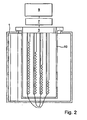
- a plurality of resistive elements 11 of different lengths are used. Resistance elements made of copper wire, for example, are suitable for this purpose.
- the actual resistances of the individual resistance elements 11 are detected via resistance transformers 5 and a multiplexer 7 and converted into digital temperature measurements, which are supplied to a higher-level unit 9. This determines the average temperature based on the level and the digital temperature measurement of the longest of the contents covered resistive element 11. In this case, preferably based on the level and the temperature to be measured separately above the contents of the contribution of not covered by the contents of this resistive element 11 to the average temperature ,
- each individual temperature sensor 3 or each individual resistance element 11 must be connected individually. Depending on the choice of these components are three or possibly four lines per component required, all of which must be performed in the probe. The number of lines and connections is correspondingly high. This results in high production costs.
- Lines and connections represent weak points of the probes. Particularly in the case of probes in which the individual temperature sensors 3 or resistance elements 11 are arranged in flexible sleeves 10, in which the lines are bundled and routed to the higher-level unit, the lines and connections are subjected to particularly high stress , If a line or a terminal is damaged, the corresponding temperature sensor 3 or the corresponding resistance element 11 drops out. This leads directly to measurement errors.
- a further disadvantage is that the length of the probe and the number of temperature sensors 3 or resistance elements 11 contained therein must be selected in advance as a function of the height of the container 1. Frequently, such temperature probes are custom-made. Warehousing or stocking the manufacturer or the customer is thereby consuming and expensive. Flexibility is not given due to the application-specific lengths.
- Another disadvantage is that the failure of a single temperature sensor 3 or resistance element 11 of the probe usually results in replacement of the entire probe. This is expensive and time consuming and can sometimes lead to significant delays for the user.
- EP 0 278 102 describes a temperature probe having a plurality of temperature sensors along a cable.
- the data sheet for thermometer DS1820 Dallas Semiconductor discloses a sensor element that can be operated with the "1-Wire interface”.
- the invention is in a temperature probe with
- a sleeve wherein the sleeve consists of individual interconnectable segments, and in each segment, a temperature sensor is arranged
- each temperature sensor is assigned a unique address
- each temperature sensor serves a local temperature in the
- the sleeve consists at least partially of an electrically conductive material. It is grounded and the temperature sensors are grounded through the grounded sleeve.
- each temperature sensor has one
- Memory for storing data on.
- the temperature sensors are each arranged in a cavity in a portion of the respective segment of the sleeve, which is filled with a potting compound.
- a line segment of the communication line to which the respective temperature sensor is connected runs in each segment, and the individual line segments have connection means on the end, via which the individual line segments of adjoining segments of the probe can be electrically connected to one another.
- connection means comprise a contact pin connected to a first end of the respective line segment and a contact sleeve connected to a second end of the respective line segment, and are insulated from the respective segment of the sleeve.
- the segments of the sleeve are connected to each other via mechanical connections, which at the same time cause an electrical connection, via which the individual segments are grounded.
- each temperature sensor is followed by a switch which is connected to ground and to the communication line, which has a unique address over which it can be detected by the higher-level unit via the communication line and individually controlled, and which is connected to the communication line so that it can assume a switch position in response to the control by the parent unit, the causes the communication line is at least temporarily interrupted, and all subsequent temperature sensors and this downstream switch are disconnected from the communication line.
- each switch is assigned a readable memory via the communication line by data is stored, via which the switch associated temperature sensor is uniquely identifiable.
- the invention consists in a method for determining an order of the temperature sensors of a temperature probe according to the last-mentioned development, in which
- Fig. 1 shows a conventional temperature probe with temperature sensors
- Fig. 2 shows a conventional temperature probe with resistive elements
- Fig. 3 shows a schematic representation of a temperature probe according to the invention
- Fig. 4 shows a view of a limb probe according to the invention
- Fig. 5 shows a segment of the limb probe completely and one on it
- Fig. 6 shows a view of a connecting element of a segment
- Fig. 7 shows a part of a segment and the tail of the probe
- Fig. 8 shows a circuit diagram of a temperature probe, which automatically a
- Fig. 9 shows the diagram of Fig. 8 , where the outputs of the
- Fig. 3 shows a schematic representation of a temperature probe according to the invention.
- the temperature probe has a mechanical fastening device 13, in the illustrated embodiment, a flange, by means of which it can be mounted on a container 1, for example on a corresponding nozzle 15.
- the fastening device 13 carries a in the illustrated example substantially tubular rigid or flexible hollow cylindrical sleeve 19, which leads in the assembled state into the container 1 into it.
- a housing 21 is arranged, in which, for example, a probe electronics can be arranged.
- a plurality of temperature sensors T1, T2 ... TN are arranged one above the other.
- Each of the temperature sensors T1 to TN is connected in parallel to the other temperature sensors to ground GND and to a stirred in the sleeve 19 communication line K.
- the sleeve 19 is at least partially made of an electrically conductive material, for example made of brass, of a stainless steel or another suitable material with regard to the media in contact with the probe, and is grounded.
- the grounding can be done for example via the probe electronics. Alternatively, the grounding can also take place via the fastening device 13 connected to the sleeve 19 and the grounded container 1.
- the earthing is to be provided for safety reasons, for example, for use in potentially explosive areas, such as those that are regularly present in the oil and gas industry.
- the connection of the temperature sensors T1, ..., TN to ground GND is preferably carried out directly, in which each temperature sensor T x is connected to ground via the grounded sleeve 19. In each case a short in Fig.
- connection GND 1 , ..., GND N from the respective ground terminal of the individual temperature sensor T1, ..., TN to an electrically conductive portion of the sleeve 19 in its immediate vicinity.
- the temperature sensors T 1 to TN are supplied with energy via the communication line K.
- the temperature probe has a higher-level unit 23 which is connected to the communication line K.
- the parent unit 23 is arranged, for example, in the housing 21.
- Each temperature sensor T x is used to measure a local temperature in its immediate vicinity and to provide these in the form of a digital temperature signal via the communication line K of the parent unit 23 available.
- Suitable temperature sensors T1, ..., TN are preferably bus-capable sensors, which are addressed and supplied via a corresponding protocol via a single bus line.
- the communication line K is a bus line, which is addressed via the individual temperature sensors T x by means of a sensor-specific protocol.
- An example of such a temperature sensor is the '1 Wire Parasite Power Digital Thermometer: DS18520 - PAR' from Dallas Semiconductor.
- These temperature sensors have a connection for the communication line K, via which they both communicate and are supplied with energy.
- the topology of these temperature sensors allows multiple temperature sensors to be connected in parallel to a single communication line K.
- the return R is via ground, here preferably via the sleeve 19.
- the sleeve 19 may be, for example, a rigid metallic tube. But it can also be flexible. This is esp. Advantageous if only little space above the container opening for the introduction of the probe is available. Since in the temperature probe according to the invention, only the communication line K and possibly ground GND are performed over the entire length of the sleeve 19, the wiring complexity within the probe is very low. The small number of required lines allows a very small diameter sleeve. In addition, especially with flexible sleeves 19, the risk of damage to the cables and the connections is significantly reduced.
- the temperature probe according to the invention is formed as a limb probe.
- Fig. 4 shows a view of a limb probe according to the invention.
- the measuring unit to be led into the container 1 consists of individual segments 27 which are connected to each other.
- the individual segments 27 are very short compared to the length of the entire probe. They can for example have a length of 0.5 m to 1.0 m.
- the segments 27 can be brought individually to the container opening, connected there one after the other and lowered into the container 1. This offers the advantage that only the height required for the connection of two segments 27 must be available above the container 1. This small height is usually present, so that the use of flexible sleeves, in which a greater mechanical stress is expected for the lines and connections contained therein, as with rigid sleeves, can be dispensed with as a rule.
- the sleeve 25 of the link probe is made up of the individual interconnectable segments 27.
- a temperature sensor T is arranged in each segment 27.
- Fig. 4 only three segments 27 are shown. However, the number of segments 27 is not set to three in any way. Rather, it is chosen as a function of the height of the container 1 and the number of for a sufficiently accurate determination of the average temperature or the temperature distribution in the container. In this case, for example, up to 20 temperature sensors T can be used.
- each segment 27 is a line segment K x of the communication line K, to which the respective temperature sensor T x is connected.
- the individual line segments K x have terminal means which are described in more detail below by way of example, via which the individual line segments K x of adjoining segments 27 of the probe can be electrically connected to one another.
- connection of the individual temperature sensors T x to ground can likewise be effected via corresponding line segments guided in the segments 27, which are connected to one another to form an earth line.
- Fig. 5 shows a segment 27a and a connectable end of another segment 27b in detail.
- the segment 27a comprises a tubular portion 29 having inside a cylindrical cavity 31 in which the temperature sensor T is arranged.
- the remaining cavity 31 is preferably filled with a potting compound 33.
- a pipe segment 35 is mounted, in which the respective line segment K x of the communication line K extends.
- the tube segment 35 is welded, for example, to a frontally arranged bore 37, through which the line segment K x of the communication line K is guided into the cavity 31.
- the line segment K x of the communication line K is connected in the cavity 31 with the corresponding terminal 39 of the temperature sensor T. This connection is protected by the rigid portion 29 of the sleeve 25 and the potting compound against mechanical stresses.
- each temperature sensor T x is connected via a short line GND x with a clamped in the cavity 31 metallic spring ring 43 which causes an electrically conductive connection to the metallic sleeve 27a, here the outer wall of the tubular portion 29.
- a connecting element 45 is arranged, which serves to establish an electrical and a mechanical connection to the next segment 27 to be mounted thereon.
- Fig. 6 shows a view of the connecting element 45.
- the connecting element 45 is made of an electrically conductive material, for example made of brass, of a stainless steel, or another with respect to the coming into contact with the probe media in contact material, and has a through bore 47th on, in which the end of the tube segment 35 opens.
- the pipe segment 35 is connected at this point via a welded joint 49 with the connecting element 45.
- a metallic contact sleeve 51 is arranged, which is isolated from the connecting element 45 by an insert 53 made of an insulator, for example a plastic.
- the contact sleeve 51 is made of gold, for example, and is connected to the line segment K x routed through the tube segment 35 of the communication line K.
- a thread 55 is integrally formed on the connecting element 45.
- the counterpart to the connecting element 45 is located on the side facing away from the pipe segment 35 side of the portion 29.
- the portion 29 is open at this end and has an internal thread 57, in which the thread 55 of each to connecting segment 27 is screwed.
- the connecting element 45 may have a hexagonal portion 58 on the outside, to which a corresponding key can be attached.
- a seal 59 e.g. an O-ring, provided, for example, can be arranged in a between the external thread 55 and welded to the connecting element 45 tube segment 35.
- the tubular section 29, the tube segment 35 and the connecting element 35 are made of an electrically conductive material, for example of brass, of a stainless steel or another suitable material with regard to the media in contact with the probe, and the individual segments 27 together form the sleeve 25.
- the individual segments 27 are connected via a mechanical connection, here the threads 55 and 57, which also causes an electrical connection between the individual segments 27.
- a mechanical connection here the threads 55 and 57
- a rod-shaped contact pin 61 preferably a spring contact, arranged, which leads out of the portion 29 and is plugged by the screwing of two adjacent segments, here 27a and 27b, in the contact sleeve 51 of the corresponding connecting element 45.
- the contact pin 61 is connected via a connection 63 of the temperature sensor T to the guided in the respective segment 27 line segment K x of the communication line K.
- connection means via which the individual line segments K x of adjoining segments 27 of the probe are electrically connectable to each other.
- connection means such as other types of connectors, can also be used here.
- the conclusion of the probe forms an in Fig. 7 represented end piece 65, which has just like the connecting elements 45 has an external thread 67 that is screwed into the internal thread 57 of the adjacent segment 27.
- the end piece 65 is essentially a pot-shaped end-closed component, which is the probe closes at the end.
- a fastening device 69 is provided on the outside of the end piece 65, which allows attachment of the probe in the container. This attachment can for example via a in Fig. 7 not shown weight, which is mounted on the fastening device 69.
- the contact pin 61 of the segment connected to the end piece 65 27 leads into the end piece 65 and is connected there to ground GND. This is preferably done via the metallic housing of the end piece 65, which is connected via the external thread 67 to the grounded sleeve 25.
- the same contact sleeve can be arranged in the end piece 65, which is also used in the connecting elements 45. In contrast to the contact sleeves 61 of the connecting elements 45, however, this is not insulated from the housing of the end piece 65, but is in direct electrical contact with the housing.
- each temperature sensor T x is assigned a unique address and each temperature sensor T x has a memory 70 for storing data, such as calibration data and the length of the segment on. In this way, the higher-level unit 23 automatically recognizes the type and number of temperature sensors T x connected thereto.
- This unique address is already in advance in the calibration of the temperature sensors T x advantage.
- Several temperature sensors T x can be calibrated at the same time in a calibration device. The assignment of the individual temperature sensors T x can be based on the addresses.
- the calibration data can then be recorded and stored, eg via a PC. Characteristic curves can be determined and the characteristic curves or the calibration data can be stored, for example via the PC, on the basis of the unique addresses directly in the memory 70 assigned to the respective temperature sensor T x .
- the parent unit 23 is in Fig. 3 schematically and includes, for example, a preferably intrinsically safe input circuit 71 to which the communication line K is connected, a communication interface 73, via which the communication with the temperature sensors T x takes place, and an electronic unit 75, such as a microcontroller or a microprocessor, for Recording, processing, processing and / or forwarding the measurement results. It is equipped with a connection 77, via which the probe is supplied with energy. In addition, an interface 81 equipped with a further connection 79 is provided, via which the probe can be connected, for example, to a programmable logic controller, a process control system or to a personal computer. Such interfaces are standard in measurement and control technology and therefore not explained in detail here. As possible examples are called only Hart and Fieldbus. Furthermore, an on-site display 83 may be provided.
- the higher-level unit 23 acquires the measurement data of the individual temperature sensors T x . Based on these measurement data, it can calculate both a detailed temperature profile and an average temperature in the vessel. When determining the mean temperature, the knowledge of the separately measured fill level in the container is preferably additionally taken into account. The current fill level can be made available to the higher-level unit 23 for this purpose, for example via the interface 81.
- the parent unit 23 requires information about the structure of the temperature probe. In addition to information about the type and number of connected temperature sensors Tx, this also includes their sequence within the probe and their installation height. In the case of a sensor which has been completely assembled at the factory, these data can be stored at the factory in the higher-level unit 23.
- sensor-specific data such as e.g. Type information, information on the length of the segment in which the respective temperature sensor is located, as well as the installation height of the respective temperature sensor in the segment, transmitted to corresponding externally applied to the individual segments markings, and after assembly of the probe via a corresponding input device of the parent unit 23 along with the order in which the individual segments or temperature sensors were mounted together, are supplied.
- FIG. 8 shows a circuit diagram of a correspondingly developed temperature probe in the example of three segments 27 are connected to the parent unit 23.
- Each segment 27 each includes a temperature sensor, here T1, T2 and T3.
- Each of these temperature sensors T1, T2 and T3 is followed by a respective switch S1, S2 and S3.
- Each switch S 1, S 2, S 3 is connected in parallel with the associated temperature sensor T 1, T 2 or T 3 to ground GND and to the segment K 1, K 2 or K 3 extending in the respective segment 27
- Communication line K is connected, and the communication line K is connected to the parent unit 23, more precisely to the electronic unit 75 contained therein.
- Each switch S1, S2, S3 has a unique address, via which it can be detected by the superordinated unit 23 via the communication line K and individually controlled.
- Each switch S1, S2, S3 is connected to the communication line K in such a way that, depending on the control by the higher-level unit 23, it can assume a switch position which causes the communication line K to be interrupted at least temporarily, and all subsequent temperature sensors T and these downstream switch S are disconnected from the communication line K. This offers the advantage that only the communication line K is used. Other lines are not required.
- a bus-capable digital switching element 85 is preferably used here, the digital output of which is used to control a base of a transistor 87 inserted in the communication line K.
- the switching element 85 is exactly like the temperature sensors T1, T2, T3 via a corresponding protocol via a single bus line, here the communication line K, supplied and addressed by means of a corresponding protocol.
- switching element 85 is the Dallas Semiconductor '1 Wire Dual Channel Addressable Switch DS2413'.
- These switching elements 85 have a connection for the communication line K, via which they both communicate and are supplied with energy.
- the topology of these switching elements 85 allows multiple switching elements 85 to be connected in parallel to a single communication line K.
- These switching elements 85 have a unique address via which they can be individually recognized and addressed by the superordinate unit 23 even if a large number of switching elements 85 are connected to the communication line K.
- Each switch S1, S2, S3 is assigned a readable memory via the communication line by data is stored, via which the switch S1, S2, S3 associated temperature sensor T1, T2, T3 is uniquely identifiable. It is irrelevant whether the memory is part of the switch S, components of the temperature sensor T or independent. It may, for example, the previously described memory 70, which is arranged in each segment 27. It is only important that the memory can be read via the communication line K, and the data contained therein allow the parent unit 23, the respective switch S assigned to the same segment 27 associated associated temperature sensor T. In addition, information about the length of the respective segment 27 and about the installation height of the respective temperature sensor in the segment 27 are preferably contained in this memory. Furthermore, calibration data can be stored both before assembly of the probe and subsequently in the memory.
- the determination of the order in which the temperature sensors T1, T2, T3 are arranged in the temperature probe now takes place in that the higher-level unit 23 first determines the connected switches S1, S2, S3 via the communication line K. For this purpose, all addresses of the achievable via the communication line K switches S1, S2, S3 are read, and determines their number.
- the higher-level unit 23 puts each switch one after the other into a switch position in which all switches following the respective switch are disconnected from the communication line K.
- the higher-level unit determines the number of switches still connected to the communication line.
- the order of the switches and the associated temperature sensors are determined on the basis of these numbers.
- switch S1 By actuating switch S1, the subsequent switches S2 and S3 are disconnected from the communication line K.
- the higher-level unit 23 registers in this state only one switch, S1. Consequently, this switch S1 must occupy the first place in the order. Based on the memory associated with the switch S 1, it is now also possible to determine the associated temperature sensor T1, which of course occupies the same place in the sequence as the associated switch S 1.
- the subsequent switch S3 is disconnected from the communication line K.
- the higher-level unit 23 registers two switches, S1 and S2, in this state. Consequently, the switch S2 and thus also the temperature sensor T2 to be assigned via the data in the memory to this switch S2 must occupy second place in the sequence.
- switch S3 is no subsequent switch of the Communication line K separated.
- the higher-level unit 23 registers three switches S1, S2 and S3 in this state. Consequently, the switch S3 and thus also the associated temperature sensor T3 must take third place in the sequence. Since a total of three switches has been determined in advance, the process is hereby completed.
- a timer 89 such as an edge-triggered monostable oscillator, are connected between.
- An embodiment of this is in Fig. 9 shown.
- the timer 89 causes the interruption of the communication line K by the respective switch S1, only for a predetermined short period, which is sufficient for the determination of the remaining in this state in the communication line K switch. This offers the advantage that a defect of a single switch can not lead to a permanent interruption of the communication line K.
- the probe according to the invention has a much smaller number of lines and connections. This makes it possible for the first time to produce probes with very small diameters, which are also very robust and inexpensive due to the small number of lines and connections.
- Another advantage of the invention is that it is possible for the first time due to the small number of lines and the associated connections to build the probe as a member probe, which is composed of individual segments 27 together.
- the segments 27 are, as described above, electrically and mechanically connectable to one another in a very simple manner. There are no special tools required. This allows the manufacturer and the user a high degree of flexibility. Instead of expensive custom-made predetermined length probes of any length from the individual segments 27 can now be assembled. It is possible for the manufacturer as well as for the user to keep individual segments 27 in stock in order to react quickly and flexibly to requirements.
- the segments 27 are the same for all probes and allow very fast and flexible probes of different lengths with different number of temperature sensors Tx together. Custom-made items are no longer required.
- the higher-level unit 23 can use its unique address to recognize which segment 27 is faulty. It is possible to replace the affected segment individually, without having to replace the entire probe.
- redundancy it is possible to provide some redundancy by, for example, using more temperature sensors T x than mandatory. The number of lines does not increase as a result. Redundancy can provide greater accuracy for the average temperature and a more detailed temperature profile. Moreover, in the case of redundancy, it is not necessary to immediately replace the corresponding segment every time a single temperature sensor fails. The remaining error-free sensors still provide a sufficiently accurate result.
- Table 1 1 container 3 temperature sensor 5 resistance converter 7 multiplexer 9 parent unit 11 resistive elements 13 fastening device 15 Support 19 shell 21 casing 23 parent unit 25 shell 27 segment 29 tubular section 31 cylindrical cavity 33 potting compound 35 pipe segment 37 drilling 39 connection 41 Earth connection 43 spring washer 45 connecting element 47 drilling 49 welded joint 51 contact sleeve 53 commitment 55 thread 57 inner thread 59 poetry 61 pin 63 connection 65 tail 67 external thread 69 fastening device 70 Storage 71 intrinsically safe input circuit 73 Communication interface 75 electronic unit 77 connection 79 connection 81 interface 83 Suburb display 85 switching element 87 transistor 89 timer
Landscapes
- Physics & Mathematics (AREA)
- General Physics & Mathematics (AREA)
- Arrangements For Transmission Of Measured Signals (AREA)
- Investigating Or Analyzing Materials Using Thermal Means (AREA)
- Investigating Or Analyzing Materials By The Use Of Ultrasonic Waves (AREA)
- Measuring Temperature Or Quantity Of Heat (AREA)
Claims (9)
- Sonde de température avec une douille (19, 25), avec une unité maître (23), et avec plusieurs capteurs de température (T1, ..., Tx) superposées dans la douille (19, 25), chaque capteur de température (T1, ..., TN) servant à mesurer une température locale dans l'environnement du capteur de température (T1, ..., TN) respectif, et une adresse univoque étant attribuée à chaque capteur de température (Tx),
caractérisée en ce
que la douille (25) est constituée de segments (27) interconnectables, et un capteur de température (T) étant disposé dans chaque segment (27),
que les capteurs de température sont chacun raccordés en parallèle, les uns par rapport aux autres, à la masse (GND) et à un câble de communication (K) acheminé dans la douille (19, 25), et qui sont alimentés en énergie par l'intermédiaire de ce câble,
que l'unité maître (23) est raccordée au câble de communication (K),
et que la température locale mesurée par chaque capteur de température est mise à la disposition de l'unité maître (23) sous la forme d'un signal de température numérique par l'intermédiaire du câble de communication (K). - Sonde de température selon la revendication 1,
caractérisée en ce
que la douille (19, 25) est constituée d'un matériau au moins partiellement électroconducteur, la douille (19, 25) est reliée à la terre et les capteurs de température (T1, ..., TN) sont raccordés à la masse par l'intermédiaire de la douille (19, 25) mise à la terre. - Sonde de température selon la revendication 1,
caractérisée en ce
que chaque capteur de température (Tx) comporte une mémoire (70) destinée à la mémorisation de données. - Sonde de température selon la revendication 1,
caractérisée en ce
que les capteurs de température (T) sont chacun disposés dans un espace creux (31), dans une section (29) du segment (27) respectif de la douille (25), espace qui est rempli d'une masse de scellement (33). - Sonde de température selon la revendication 1,
caractérisée en ce
qu'un segment de câble (Kx) du câble de communication (K) est posé dans chaque segment (27), auquel segment de câble le capteur de température (Tx) respectif est raccordé, et en ce que les différents segments de câble (Kx) présentent en leurs extrémités des moyens de raccordement, par l'intermédiaire desquels les différents segments de câble (Kx) de segments (27) contigus de la sonde peuvent être reliés électriquement entre eux. - Sonde de température selon la revendication 5,
caractérisée en ce
que les moyens de raccordement présentent une broche de contact (61) raccordée à une première extrémité du segment de câble (Kx) respectif et une douille de contact (51) disposée à une deuxième extrémité du segment de câble (Kx) respectif, et que les moyens de raccordement sont isolés par rapport au segment (27) respectif de la douille (25). - Sonde de température selon la revendication 1,
caractérisée en ce
que les segments (27) de la douille (25) sont reliés entre eux par l'intermédiaire de liaisons mécaniques, qui assurent en même temps une liaison électrique, par l'intermédiaire desquels les différents segments (27) sont mis à la terre. - Sonde de température selon l'une des revendications précédentes,
caractérisée en ce- qu'à chaque capteur de température (T1, T2, T3) est couplé en aval un interrupteur (S1, S2, S3),- - qui est raccordé à la masse (GND) et au câble de communication (K),- - qui dispose d'une adresse univoque, par l'intermédiaire de laquelle il peut être reconnu et commandé individuellement par l'unité maître (23) via le câble de communication (K),- - qui est raccordé au câble de communication (K) de telle manière- -- à pouvoir adopter une position d'interrupteur en fonction de la commande effectuée par l'unité maître (23), laquelle position produit une interruption au moins temporaire du câble de communication (K), et tous les capteurs de température aval et les interrupteurs couplés en aval par rapport à ces capteurs sont déconnectés du câble de communication (K), et- qu'à chaque interrupteur (S1, S2, S3) est attribuée une mémoire (70) lisible par l'intermédiaire du câble de communication (K), mémoire dans laquelle sont enregistrées des données, par l'intermédiaire desquelles le capteur de température (T1, T2, T3) correspondant à l'interrupteur (S1, S2, S3) peut être identifié de façon univoque. - Procédé destiné à la détermination d'un ordre de capteurs de température d'une sonde de température selon la revendication 8,
caractérisé en ce que- l'unité maître (23) définit les interrupteurs (S1, S2, S3) raccordés par l'intermédiaire du câble de communication (K),- l'unité maître (23) place chacun des interrupteurs (S1, S2, S3) successivement dans une position d'interrupteur, dans laquelle tous les interrupteurs placés en aval de l'interrupteur respectif sont déconnectés par le câble de communication (K),- l'unité maître (23) détermine dans cet état le nombre des interrupteurs encore raccordés au câble de communication (K), et- détermine l'ordre des interrupteurs (S1, S2, S3) et les capteurs de température correspondants sur la base de ce nombre.
Applications Claiming Priority (2)
| Application Number | Priority Date | Filing Date | Title |
|---|---|---|---|
| DE102006026515A DE102006026515A1 (de) | 2006-06-06 | 2006-06-06 | Temperatursonde |
| PCT/EP2007/055515 WO2007141265A1 (fr) | 2006-06-06 | 2007-06-05 | Sonde de température |
Publications (2)
| Publication Number | Publication Date |
|---|---|
| EP2024719A1 EP2024719A1 (fr) | 2009-02-18 |
| EP2024719B1 true EP2024719B1 (fr) | 2010-12-22 |
Family
ID=38474449
Family Applications (1)
| Application Number | Title | Priority Date | Filing Date |
|---|---|---|---|
| EP07729895A Not-in-force EP2024719B1 (fr) | 2006-06-06 | 2007-06-05 | Sonde de temperature |
Country Status (4)
| Country | Link |
|---|---|
| EP (1) | EP2024719B1 (fr) |
| AT (1) | ATE492793T1 (fr) |
| DE (2) | DE102006026515A1 (fr) |
| WO (1) | WO2007141265A1 (fr) |
Families Citing this family (3)
| Publication number | Priority date | Publication date | Assignee | Title |
|---|---|---|---|---|
| DE102009051304B3 (de) * | 2009-10-29 | 2011-02-17 | Robert Bosch Gmbh | Warmwasserversorgungseinrichtung, Regeleinrichtung, Vorrichtung und Verfahren zur Temperaturprofilmessung eines Mediums in einem Speicher |
| DE102017206424A1 (de) | 2017-04-13 | 2018-10-18 | Siemens Aktiengesellschaft | Anordnung und Verfahren zur Füllstandsmessung |
| CN113267270A (zh) * | 2021-03-30 | 2021-08-17 | 贵州电网有限责任公司 | 一种实时检测变压器桩头及线路接头温升预警器 |
Family Cites Families (5)
| Publication number | Priority date | Publication date | Assignee | Title |
|---|---|---|---|---|
| GB1291827A (en) * | 1968-10-28 | 1972-10-04 | Rosemount Eng Co Ltd | Improvements in or relating to temperature measuring apparatus |
| DE8709641U1 (de) * | 1986-07-21 | 1987-11-26 | Unimess Messtechnische Geräte GmbH, 6308 Butzbach | Temperaturmeßsonde |
| US4878226A (en) * | 1987-02-09 | 1989-10-31 | Combustion Engineering, Inc. | Multiple point remote temperature sensing |
| EP0278102A3 (fr) * | 1987-02-09 | 1990-06-06 | Combustion Engineering, Inc. | Mesure de température à points multiples à distance |
| JPH02147927A (ja) * | 1988-11-30 | 1990-06-06 | Sukegawa Electric Co Ltd | 温度計測システム |
-
2006
- 2006-06-06 DE DE102006026515A patent/DE102006026515A1/de not_active Withdrawn
-
2007
- 2007-06-05 AT AT07729895T patent/ATE492793T1/de active
- 2007-06-05 WO PCT/EP2007/055515 patent/WO2007141265A1/fr not_active Ceased
- 2007-06-05 EP EP07729895A patent/EP2024719B1/fr not_active Not-in-force
- 2007-06-05 DE DE502007006035T patent/DE502007006035D1/de active Active
Also Published As
| Publication number | Publication date |
|---|---|
| ATE492793T1 (de) | 2011-01-15 |
| DE102006026515A1 (de) | 2007-12-13 |
| WO2007141265A1 (fr) | 2007-12-13 |
| DE502007006035D1 (de) | 2011-02-03 |
| EP2024719A1 (fr) | 2009-02-18 |
Similar Documents
| Publication | Publication Date | Title |
|---|---|---|
| EP1818672B1 (fr) | Dispositif de mesure et procédé destinés au fonctionnement du dispositif de mesure | |
| EP2269009B1 (fr) | Transducteur de mesure pour l'instrumentation de procédés et procédé pour contrôler l'état du capteur de ce transducteur | |
| DE102004050079A1 (de) | Feldmontiertes Zweileiter-Prozeßgerät | |
| WO2004086030A1 (fr) | Module de detection de gaz equipe d'une interface sans contact | |
| DE102020123409A1 (de) | Eigensicheres Feldgerät der Automatisierungstechnik | |
| EP1079219A2 (fr) | Procédé et capteur pour mesurer la température d'un milieu fluide | |
| EP2024719A1 (fr) | Sonde de temperature | |
| DE102014111350A1 (de) | Automatisierte Erstellung von geeigneten Vorzugsmenüs für Feldgeräte | |
| EP1431768B1 (fr) | Procédé et dispositif de mesure de la résistivité d'un élément de résistance sensible à la température | |
| DE102010062657A1 (de) | Bereitstellung von Kalibrierungsdaten zu Messeinrichtungen | |
| WO2023066590A1 (fr) | Dispositif de terrain pour automatisation à sécurité intrinsèque | |
| DE102012021847B4 (de) | Universelle Ein-Ausgabe-Schnittstelle für industrielle Anwendungen | |
| DE2531784C2 (de) | Meßanordnung zur Temperatur- und Druckmessung eines Mediums in Bohrlöchern | |
| DE102005029045A1 (de) | Vorrichtung und Verfahren zur Bestimmung und/oder Überwachung der Temperatur | |
| DE102004052490A1 (de) | Modulares Feldgerät für die Automatisierungstechnik | |
| DE102022106846A1 (de) | Eigensicheres Feldgerät der Automatisierungstechnik | |
| EP3376167A1 (fr) | Chaîne de mesure de déplacement | |
| WO2012119829A1 (fr) | Dispositif de mesure à compensation d'un mode de réponse retardé | |
| WO2020048743A1 (fr) | Insert de mesure avec surveillance de l'état | |
| DE102015100661A1 (de) | Vorrichtung zur Bestimmung und/oder Überwachung mindestens einer physikalischen oder chemischen Prozessgröße eines Mediums | |
| DE3201708A1 (de) | Fuehler zur bestimmung der standhoehe von fluessigen gasen | |
| DE10309125B4 (de) | Vorrichtung und Verfahren zur Spannungsstabilisierung für einen Zweidrahtfeldbus | |
| DE102015113238A1 (de) | Temperaturmessgerät zur Messung der Temperatur eines Mediums | |
| EP4211517B1 (fr) | Dispositif de terrain pour automatisation à utiliser dans une zone potentiellement explosive | |
| EP1910789B1 (fr) | Unite d'evaluation pour thermoelements continus |
Legal Events
| Date | Code | Title | Description |
|---|---|---|---|
| PUAI | Public reference made under article 153(3) epc to a published international application that has entered the european phase |
Free format text: ORIGINAL CODE: 0009012 |
|
| 17P | Request for examination filed |
Effective date: 20081204 |
|
| AK | Designated contracting states |
Kind code of ref document: A1 Designated state(s): AT BE BG CH CY CZ DE DK EE ES FI FR GB GR HU IE IS IT LI LT LU LV MC MT NL PL PT RO SE SI SK TR |
|
| AX | Request for extension of the european patent |
Extension state: AL BA HR MK RS |
|
| 17Q | First examination report despatched |
Effective date: 20090720 |
|
| GRAP | Despatch of communication of intention to grant a patent |
Free format text: ORIGINAL CODE: EPIDOSNIGR1 |
|
| GRAS | Grant fee paid |
Free format text: ORIGINAL CODE: EPIDOSNIGR3 |
|
| GRAA | (expected) grant |
Free format text: ORIGINAL CODE: 0009210 |
|
| AK | Designated contracting states |
Kind code of ref document: B1 Designated state(s): AT BE BG CH CY CZ DE DK EE ES FI FR GB GR HU IE IS IT LI LT LU LV MC MT NL PL PT RO SE SI SK TR |
|
| REG | Reference to a national code |
Ref country code: GB Ref legal event code: FG4D Free format text: NOT ENGLISH |
|
| REG | Reference to a national code |
Ref country code: CH Ref legal event code: EP |
|
| REG | Reference to a national code |
Ref country code: IE Ref legal event code: FG4D |
|
| REF | Corresponds to: |
Ref document number: 502007006035 Country of ref document: DE Date of ref document: 20110203 Kind code of ref document: P |
|
| REG | Reference to a national code |
Ref country code: DE Ref legal event code: R096 Ref document number: 502007006035 Country of ref document: DE Effective date: 20110203 |
|
| REG | Reference to a national code |
Ref country code: NL Ref legal event code: VDEP Effective date: 20101222 |
|
| PG25 | Lapsed in a contracting state [announced via postgrant information from national office to epo] |
Ref country code: LT Free format text: LAPSE BECAUSE OF FAILURE TO SUBMIT A TRANSLATION OF THE DESCRIPTION OR TO PAY THE FEE WITHIN THE PRESCRIBED TIME-LIMIT Effective date: 20101222 |
|
| LTIE | Lt: invalidation of european patent or patent extension |
Effective date: 20101222 |
|
| PG25 | Lapsed in a contracting state [announced via postgrant information from national office to epo] |
Ref country code: SI Free format text: LAPSE BECAUSE OF FAILURE TO SUBMIT A TRANSLATION OF THE DESCRIPTION OR TO PAY THE FEE WITHIN THE PRESCRIBED TIME-LIMIT Effective date: 20101222 Ref country code: FI Free format text: LAPSE BECAUSE OF FAILURE TO SUBMIT A TRANSLATION OF THE DESCRIPTION OR TO PAY THE FEE WITHIN THE PRESCRIBED TIME-LIMIT Effective date: 20101222 Ref country code: BG Free format text: LAPSE BECAUSE OF FAILURE TO SUBMIT A TRANSLATION OF THE DESCRIPTION OR TO PAY THE FEE WITHIN THE PRESCRIBED TIME-LIMIT Effective date: 20110322 Ref country code: LV Free format text: LAPSE BECAUSE OF FAILURE TO SUBMIT A TRANSLATION OF THE DESCRIPTION OR TO PAY THE FEE WITHIN THE PRESCRIBED TIME-LIMIT Effective date: 20101222 Ref country code: SE Free format text: LAPSE BECAUSE OF FAILURE TO SUBMIT A TRANSLATION OF THE DESCRIPTION OR TO PAY THE FEE WITHIN THE PRESCRIBED TIME-LIMIT Effective date: 20101222 Ref country code: CY Free format text: LAPSE BECAUSE OF FAILURE TO SUBMIT A TRANSLATION OF THE DESCRIPTION OR TO PAY THE FEE WITHIN THE PRESCRIBED TIME-LIMIT Effective date: 20101222 |
|
| REG | Reference to a national code |
Ref country code: IE Ref legal event code: FD4D |
|
| PG25 | Lapsed in a contracting state [announced via postgrant information from national office to epo] |
Ref country code: GR Free format text: LAPSE BECAUSE OF FAILURE TO SUBMIT A TRANSLATION OF THE DESCRIPTION OR TO PAY THE FEE WITHIN THE PRESCRIBED TIME-LIMIT Effective date: 20110323 Ref country code: IS Free format text: LAPSE BECAUSE OF FAILURE TO SUBMIT A TRANSLATION OF THE DESCRIPTION OR TO PAY THE FEE WITHIN THE PRESCRIBED TIME-LIMIT Effective date: 20110422 Ref country code: CZ Free format text: LAPSE BECAUSE OF FAILURE TO SUBMIT A TRANSLATION OF THE DESCRIPTION OR TO PAY THE FEE WITHIN THE PRESCRIBED TIME-LIMIT Effective date: 20101222 Ref country code: ES Free format text: LAPSE BECAUSE OF FAILURE TO SUBMIT A TRANSLATION OF THE DESCRIPTION OR TO PAY THE FEE WITHIN THE PRESCRIBED TIME-LIMIT Effective date: 20110402 Ref country code: PT Free format text: LAPSE BECAUSE OF FAILURE TO SUBMIT A TRANSLATION OF THE DESCRIPTION OR TO PAY THE FEE WITHIN THE PRESCRIBED TIME-LIMIT Effective date: 20110422 Ref country code: EE Free format text: LAPSE BECAUSE OF FAILURE TO SUBMIT A TRANSLATION OF THE DESCRIPTION OR TO PAY THE FEE WITHIN THE PRESCRIBED TIME-LIMIT Effective date: 20101222 |
|
| PG25 | Lapsed in a contracting state [announced via postgrant information from national office to epo] |
Ref country code: RO Free format text: LAPSE BECAUSE OF FAILURE TO SUBMIT A TRANSLATION OF THE DESCRIPTION OR TO PAY THE FEE WITHIN THE PRESCRIBED TIME-LIMIT Effective date: 20101222 Ref country code: SK Free format text: LAPSE BECAUSE OF FAILURE TO SUBMIT A TRANSLATION OF THE DESCRIPTION OR TO PAY THE FEE WITHIN THE PRESCRIBED TIME-LIMIT Effective date: 20101222 Ref country code: PL Free format text: LAPSE BECAUSE OF FAILURE TO SUBMIT A TRANSLATION OF THE DESCRIPTION OR TO PAY THE FEE WITHIN THE PRESCRIBED TIME-LIMIT Effective date: 20101222 Ref country code: NL Free format text: LAPSE BECAUSE OF FAILURE TO SUBMIT A TRANSLATION OF THE DESCRIPTION OR TO PAY THE FEE WITHIN THE PRESCRIBED TIME-LIMIT Effective date: 20101222 |
|
| PLBE | No opposition filed within time limit |
Free format text: ORIGINAL CODE: 0009261 |
|
| STAA | Information on the status of an ep patent application or granted ep patent |
Free format text: STATUS: NO OPPOSITION FILED WITHIN TIME LIMIT |
|
| PG25 | Lapsed in a contracting state [announced via postgrant information from national office to epo] |
Ref country code: IE Free format text: LAPSE BECAUSE OF FAILURE TO SUBMIT A TRANSLATION OF THE DESCRIPTION OR TO PAY THE FEE WITHIN THE PRESCRIBED TIME-LIMIT Effective date: 20101222 Ref country code: DK Free format text: LAPSE BECAUSE OF FAILURE TO SUBMIT A TRANSLATION OF THE DESCRIPTION OR TO PAY THE FEE WITHIN THE PRESCRIBED TIME-LIMIT Effective date: 20101222 |
|
| 26N | No opposition filed |
Effective date: 20110923 |
|
| PG25 | Lapsed in a contracting state [announced via postgrant information from national office to epo] |
Ref country code: IT Free format text: LAPSE BECAUSE OF FAILURE TO SUBMIT A TRANSLATION OF THE DESCRIPTION OR TO PAY THE FEE WITHIN THE PRESCRIBED TIME-LIMIT Effective date: 20101222 Ref country code: MT Free format text: LAPSE BECAUSE OF FAILURE TO SUBMIT A TRANSLATION OF THE DESCRIPTION OR TO PAY THE FEE WITHIN THE PRESCRIBED TIME-LIMIT Effective date: 20101222 |
|
| BERE | Be: lapsed |
Owner name: ENDRESS+HAUSER GMBH+CO. K.G. Effective date: 20110630 |
|
| REG | Reference to a national code |
Ref country code: DE Ref legal event code: R097 Ref document number: 502007006035 Country of ref document: DE Effective date: 20110923 |
|
| REG | Reference to a national code |
Ref country code: CH Ref legal event code: PL |
|
| GBPC | Gb: european patent ceased through non-payment of renewal fee |
Effective date: 20110605 |
|
| PG25 | Lapsed in a contracting state [announced via postgrant information from national office to epo] |
Ref country code: BE Free format text: LAPSE BECAUSE OF NON-PAYMENT OF DUE FEES Effective date: 20110630 |
|
| PG25 | Lapsed in a contracting state [announced via postgrant information from national office to epo] |
Ref country code: CH Free format text: LAPSE BECAUSE OF NON-PAYMENT OF DUE FEES Effective date: 20110630 Ref country code: LI Free format text: LAPSE BECAUSE OF NON-PAYMENT OF DUE FEES Effective date: 20110630 |
|
| PG25 | Lapsed in a contracting state [announced via postgrant information from national office to epo] |
Ref country code: GB Free format text: LAPSE BECAUSE OF NON-PAYMENT OF DUE FEES Effective date: 20110605 |
|
| PG25 | Lapsed in a contracting state [announced via postgrant information from national office to epo] |
Ref country code: MC Free format text: LAPSE BECAUSE OF NON-PAYMENT OF DUE FEES Effective date: 20110630 |
|
| PG25 | Lapsed in a contracting state [announced via postgrant information from national office to epo] |
Ref country code: LU Free format text: LAPSE BECAUSE OF NON-PAYMENT OF DUE FEES Effective date: 20110605 |
|
| REG | Reference to a national code |
Ref country code: AT Ref legal event code: MM01 Ref document number: 492793 Country of ref document: AT Kind code of ref document: T Effective date: 20120605 |
|
| PG25 | Lapsed in a contracting state [announced via postgrant information from national office to epo] |
Ref country code: TR Free format text: LAPSE BECAUSE OF FAILURE TO SUBMIT A TRANSLATION OF THE DESCRIPTION OR TO PAY THE FEE WITHIN THE PRESCRIBED TIME-LIMIT Effective date: 20101222 |
|
| PG25 | Lapsed in a contracting state [announced via postgrant information from national office to epo] |
Ref country code: HU Free format text: LAPSE BECAUSE OF FAILURE TO SUBMIT A TRANSLATION OF THE DESCRIPTION OR TO PAY THE FEE WITHIN THE PRESCRIBED TIME-LIMIT Effective date: 20101222 Ref country code: AT Free format text: LAPSE BECAUSE OF NON-PAYMENT OF DUE FEES Effective date: 20120605 |
|
| REG | Reference to a national code |
Ref country code: FR Ref legal event code: PLFP Year of fee payment: 10 |
|
| PGFP | Annual fee paid to national office [announced via postgrant information from national office to epo] |
Ref country code: DE Payment date: 20160621 Year of fee payment: 10 |
|
| PGFP | Annual fee paid to national office [announced via postgrant information from national office to epo] |
Ref country code: FR Payment date: 20160627 Year of fee payment: 10 |
|
| REG | Reference to a national code |
Ref country code: DE Ref legal event code: R119 Ref document number: 502007006035 Country of ref document: DE |
|
| REG | Reference to a national code |
Ref country code: FR Ref legal event code: ST Effective date: 20180228 |
|
| PG25 | Lapsed in a contracting state [announced via postgrant information from national office to epo] |
Ref country code: DE Free format text: LAPSE BECAUSE OF NON-PAYMENT OF DUE FEES Effective date: 20180103 |
|
| PG25 | Lapsed in a contracting state [announced via postgrant information from national office to epo] |
Ref country code: FR Free format text: LAPSE BECAUSE OF NON-PAYMENT OF DUE FEES Effective date: 20170630 |