EP2025427A2 - Procédé pour réaliser un échangeur de chaleur et échangeur de chaleur - Google Patents
Procédé pour réaliser un échangeur de chaleur et échangeur de chaleur Download PDFInfo
- Publication number
- EP2025427A2 EP2025427A2 EP08252456A EP08252456A EP2025427A2 EP 2025427 A2 EP2025427 A2 EP 2025427A2 EP 08252456 A EP08252456 A EP 08252456A EP 08252456 A EP08252456 A EP 08252456A EP 2025427 A2 EP2025427 A2 EP 2025427A2
- Authority
- EP
- European Patent Office
- Prior art keywords
- heat exchanger
- mandrel
- shells
- shell
- hollow heat
- Prior art date
- Legal status (The legal status is an assumption and is not a legal conclusion. Google has not performed a legal analysis and makes no representation as to the accuracy of the status listed.)
- Granted
Links
- 238000000034 method Methods 0.000 title claims description 33
- 238000005323 electroforming Methods 0.000 claims abstract description 21
- 239000011248 coating agent Substances 0.000 claims description 10
- 238000000576 coating method Methods 0.000 claims description 10
- 239000004020 conductor Substances 0.000 claims description 7
- 238000005219 brazing Methods 0.000 claims description 6
- 238000007747 plating Methods 0.000 claims description 6
- 238000005530 etching Methods 0.000 claims description 5
- 230000008018 melting Effects 0.000 claims description 5
- 238000002844 melting Methods 0.000 claims description 5
- 238000009713 electroplating Methods 0.000 claims description 4
- 238000001704 evaporation Methods 0.000 claims description 4
- 238000004070 electrodeposition Methods 0.000 claims description 2
- FGUUSXIOTUKUDN-IBGZPJMESA-N C1(=CC=CC=C1)N1C2=C(NC([C@H](C1)NC=1OC(=NN=1)C1=CC=CC=C1)=O)C=CC=C2 Chemical compound C1(=CC=CC=C1)N1C2=C(NC([C@H](C1)NC=1OC(=NN=1)C1=CC=CC=C1)=O)C=CC=C2 FGUUSXIOTUKUDN-IBGZPJMESA-N 0.000 claims 1
- 239000000463 material Substances 0.000 abstract description 24
- 239000012530 fluid Substances 0.000 description 17
- 230000008569 process Effects 0.000 description 13
- 238000013461 design Methods 0.000 description 12
- 238000000151 deposition Methods 0.000 description 7
- 230000008021 deposition Effects 0.000 description 6
- 238000012546 transfer Methods 0.000 description 6
- 238000003825 pressing Methods 0.000 description 5
- 238000003754 machining Methods 0.000 description 4
- 230000008878 coupling Effects 0.000 description 3
- 238000010168 coupling process Methods 0.000 description 3
- 238000005859 coupling reaction Methods 0.000 description 3
- 238000009792 diffusion process Methods 0.000 description 3
- 230000008020 evaporation Effects 0.000 description 3
- 238000004519 manufacturing process Methods 0.000 description 3
- 239000011159 matrix material Substances 0.000 description 3
- RYGMFSIKBFXOCR-UHFFFAOYSA-N Copper Chemical compound [Cu] RYGMFSIKBFXOCR-UHFFFAOYSA-N 0.000 description 2
- PXHVJJICTQNCMI-UHFFFAOYSA-N Nickel Chemical compound [Ni] PXHVJJICTQNCMI-UHFFFAOYSA-N 0.000 description 2
- 239000000853 adhesive Substances 0.000 description 2
- 230000001070 adhesive effect Effects 0.000 description 2
- 229910045601 alloy Inorganic materials 0.000 description 2
- 239000000956 alloy Substances 0.000 description 2
- 230000006835 compression Effects 0.000 description 2
- 238000007906 compression Methods 0.000 description 2
- 229910052802 copper Inorganic materials 0.000 description 2
- 239000010949 copper Substances 0.000 description 2
- 238000009826 distribution Methods 0.000 description 2
- 239000012799 electrically-conductive coating Substances 0.000 description 2
- 238000001746 injection moulding Methods 0.000 description 2
- 229910052751 metal Inorganic materials 0.000 description 2
- 239000002184 metal Substances 0.000 description 2
- 230000002787 reinforcement Effects 0.000 description 2
- 238000007789 sealing Methods 0.000 description 2
- UPSUNDAUJOYTKX-UHFFFAOYSA-N [W].[Ni].[Co].[Ni] Chemical compound [W].[Ni].[Co].[Ni] UPSUNDAUJOYTKX-UHFFFAOYSA-N 0.000 description 1
- 206010000496 acne Diseases 0.000 description 1
- 230000004075 alteration Effects 0.000 description 1
- 238000013459 approach Methods 0.000 description 1
- 230000000712 assembly Effects 0.000 description 1
- 238000000429 assembly Methods 0.000 description 1
- 230000015572 biosynthetic process Effects 0.000 description 1
- 238000004140 cleaning Methods 0.000 description 1
- 238000007596 consolidation process Methods 0.000 description 1
- 238000010276 construction Methods 0.000 description 1
- 230000007797 corrosion Effects 0.000 description 1
- 238000005260 corrosion Methods 0.000 description 1
- 238000007598 dipping method Methods 0.000 description 1
- 230000000694 effects Effects 0.000 description 1
- 238000007772 electroless plating Methods 0.000 description 1
- 239000003792 electrolyte Substances 0.000 description 1
- 230000003628 erosive effect Effects 0.000 description 1
- 238000002474 experimental method Methods 0.000 description 1
- 238000007499 fusion processing Methods 0.000 description 1
- 238000009499 grossing Methods 0.000 description 1
- 230000036541 health Effects 0.000 description 1
- 238000002347 injection Methods 0.000 description 1
- 239000007924 injection Substances 0.000 description 1
- 238000009413 insulation Methods 0.000 description 1
- 238000012423 maintenance Methods 0.000 description 1
- 230000036244 malformation Effects 0.000 description 1
- 238000012986 modification Methods 0.000 description 1
- 230000004048 modification Effects 0.000 description 1
- 229910052759 nickel Inorganic materials 0.000 description 1
- 235000012771 pancakes Nutrition 0.000 description 1
- OFNHPGDEEMZPFG-UHFFFAOYSA-N phosphanylidynenickel Chemical compound [P].[Ni] OFNHPGDEEMZPFG-UHFFFAOYSA-N 0.000 description 1
- 230000009467 reduction Effects 0.000 description 1
- 230000001105 regulatory effect Effects 0.000 description 1
- 230000008439 repair process Effects 0.000 description 1
- 230000000717 retained effect Effects 0.000 description 1
- 238000000926 separation method Methods 0.000 description 1
- 230000035939 shock Effects 0.000 description 1
- 239000000243 solution Substances 0.000 description 1
- 238000005507 spraying Methods 0.000 description 1
- 238000001771 vacuum deposition Methods 0.000 description 1
Images

Classifications
-
- F—MECHANICAL ENGINEERING; LIGHTING; HEATING; WEAPONS; BLASTING
- F28—HEAT EXCHANGE IN GENERAL
- F28F—DETAILS OF HEAT-EXCHANGE AND HEAT-TRANSFER APPARATUS, OF GENERAL APPLICATION
- F28F3/00—Plate-like or laminated elements; Assemblies of plate-like or laminated elements
- F28F3/08—Elements constructed for building-up into stacks, e.g. capable of being taken apart for cleaning
-
- F—MECHANICAL ENGINEERING; LIGHTING; HEATING; WEAPONS; BLASTING
- F28—HEAT EXCHANGE IN GENERAL
- F28F—DETAILS OF HEAT-EXCHANGE AND HEAT-TRANSFER APPARATUS, OF GENERAL APPLICATION
- F28F3/00—Plate-like or laminated elements; Assemblies of plate-like or laminated elements
-
- B—PERFORMING OPERATIONS; TRANSPORTING
- B21—MECHANICAL METAL-WORKING WITHOUT ESSENTIALLY REMOVING MATERIAL; PUNCHING METAL
- B21D—WORKING OR PROCESSING OF SHEET METAL OR METAL TUBES, RODS OR PROFILES WITHOUT ESSENTIALLY REMOVING MATERIAL; PUNCHING METAL
- B21D53/00—Making other particular articles
- B21D53/02—Making other particular articles heat exchangers or parts thereof, e.g. radiators, condensers fins, headers
-
- C—CHEMISTRY; METALLURGY
- C25—ELECTROLYTIC OR ELECTROPHORETIC PROCESSES; APPARATUS THEREFOR
- C25D—PROCESSES FOR THE ELECTROLYTIC OR ELECTROPHORETIC PRODUCTION OF COATINGS; ELECTROFORMING; APPARATUS THEREFOR
- C25D1/00—Electroforming
- C25D1/02—Tubes; Rings; Hollow bodies
-
- F—MECHANICAL ENGINEERING; LIGHTING; HEATING; WEAPONS; BLASTING
- F28—HEAT EXCHANGE IN GENERAL
- F28D—HEAT-EXCHANGE APPARATUS, NOT PROVIDED FOR IN ANOTHER SUBCLASS, IN WHICH THE HEAT-EXCHANGE MEDIA DO NOT COME INTO DIRECT CONTACT
- F28D1/00—Heat-exchange apparatus having stationary conduit assemblies for one heat-exchange medium only, the media being in contact with different sides of the conduit wall, in which the other heat-exchange medium is a large body of fluid, e.g. domestic or motor car radiators
- F28D1/02—Heat-exchange apparatus having stationary conduit assemblies for one heat-exchange medium only, the media being in contact with different sides of the conduit wall, in which the other heat-exchange medium is a large body of fluid, e.g. domestic or motor car radiators with heat-exchange conduits immersed in the body of fluid
- F28D1/03—Heat-exchange apparatus having stationary conduit assemblies for one heat-exchange medium only, the media being in contact with different sides of the conduit wall, in which the other heat-exchange medium is a large body of fluid, e.g. domestic or motor car radiators with heat-exchange conduits immersed in the body of fluid with plate-like or laminated conduits
- F28D1/0308—Heat-exchange apparatus having stationary conduit assemblies for one heat-exchange medium only, the media being in contact with different sides of the conduit wall, in which the other heat-exchange medium is a large body of fluid, e.g. domestic or motor car radiators with heat-exchange conduits immersed in the body of fluid with plate-like or laminated conduits the conduits being formed by paired plates touching each other
- F28D1/0325—Heat-exchange apparatus having stationary conduit assemblies for one heat-exchange medium only, the media being in contact with different sides of the conduit wall, in which the other heat-exchange medium is a large body of fluid, e.g. domestic or motor car radiators with heat-exchange conduits immersed in the body of fluid with plate-like or laminated conduits the conduits being formed by paired plates touching each other the plates having lateral openings therein for circulation of the heat-exchange medium from one conduit to another
- F28D1/0333—Heat-exchange apparatus having stationary conduit assemblies for one heat-exchange medium only, the media being in contact with different sides of the conduit wall, in which the other heat-exchange medium is a large body of fluid, e.g. domestic or motor car radiators with heat-exchange conduits immersed in the body of fluid with plate-like or laminated conduits the conduits being formed by paired plates touching each other the plates having lateral openings therein for circulation of the heat-exchange medium from one conduit to another the plates having integrated connecting members
-
- F—MECHANICAL ENGINEERING; LIGHTING; HEATING; WEAPONS; BLASTING
- F28—HEAT EXCHANGE IN GENERAL
- F28F—DETAILS OF HEAT-EXCHANGE AND HEAT-TRANSFER APPARATUS, OF GENERAL APPLICATION
- F28F3/00—Plate-like or laminated elements; Assemblies of plate-like or laminated elements
- F28F3/02—Elements or assemblies thereof with means for increasing heat-transfer area, e.g. with fins, with recesses, with corrugations
-
- F—MECHANICAL ENGINEERING; LIGHTING; HEATING; WEAPONS; BLASTING
- F28—HEAT EXCHANGE IN GENERAL
- F28F—DETAILS OF HEAT-EXCHANGE AND HEAT-TRANSFER APPARATUS, OF GENERAL APPLICATION
- F28F3/00—Plate-like or laminated elements; Assemblies of plate-like or laminated elements
- F28F3/02—Elements or assemblies thereof with means for increasing heat-transfer area, e.g. with fins, with recesses, with corrugations
- F28F3/04—Elements or assemblies thereof with means for increasing heat-transfer area, e.g. with fins, with recesses, with corrugations the means being integral with the element
- F28F3/042—Elements or assemblies thereof with means for increasing heat-transfer area, e.g. with fins, with recesses, with corrugations the means being integral with the element in the form of local deformations of the element
- F28F3/046—Elements or assemblies thereof with means for increasing heat-transfer area, e.g. with fins, with recesses, with corrugations the means being integral with the element in the form of local deformations of the element the deformations being linear, e.g. corrugations
-
- Y—GENERAL TAGGING OF NEW TECHNOLOGICAL DEVELOPMENTS; GENERAL TAGGING OF CROSS-SECTIONAL TECHNOLOGIES SPANNING OVER SEVERAL SECTIONS OF THE IPC; TECHNICAL SUBJECTS COVERED BY FORMER USPC CROSS-REFERENCE ART COLLECTIONS [XRACs] AND DIGESTS
- Y10—TECHNICAL SUBJECTS COVERED BY FORMER USPC
- Y10T—TECHNICAL SUBJECTS COVERED BY FORMER US CLASSIFICATION
- Y10T29/00—Metal working
- Y10T29/49—Method of mechanical manufacture
- Y10T29/4935—Heat exchanger or boiler making
-
- Y—GENERAL TAGGING OF NEW TECHNOLOGICAL DEVELOPMENTS; GENERAL TAGGING OF CROSS-SECTIONAL TECHNOLOGIES SPANNING OVER SEVERAL SECTIONS OF THE IPC; TECHNICAL SUBJECTS COVERED BY FORMER USPC CROSS-REFERENCE ART COLLECTIONS [XRACs] AND DIGESTS
- Y10—TECHNICAL SUBJECTS COVERED BY FORMER USPC
- Y10T—TECHNICAL SUBJECTS COVERED BY FORMER US CLASSIFICATION
- Y10T29/00—Metal working
- Y10T29/49—Method of mechanical manufacture
- Y10T29/4935—Heat exchanger or boiler making
- Y10T29/49366—Sheet joined to sheet
Definitions
- the present invention relates to heat exchangers and more particularly to corrugated type heat exchangers used in order to achieve high thermal transfer efficiencies.
- More recently plate or cross-corrugated heat exchangers have been provided which comprise a stack of pre-formed layers of material secured together through a fusion process at points and lines of contact between the plates.
- the plates generally have shallow corrugations formed by the pressing process and it will be appreciated that the pressing process presents severe limitations with regard to achieving more efficient deeper corrugations. Deeper corrugations will allow a stiffer structure to be achieved for a given flow path density which is therefore less prone to buckling under compression.
- pressing of a flat sheet is limited by elongation effects thus for example a pitch to depth ratio of 2.2 would require an average elongation of about 40% which is not practical for most materials suitable for forming heat exchangers.
- heat exchangers are designed for a multitude of environments and uses, and in some circumstances heat exchanger weight and structural strength are not as important as in other uses where heat exchanger weight and strength as well as thermo hydraulic performance are more critical for acceptability.
- the coating is formed by electro-forming onto the mandrel which is an electrode.
- the coating is formed by electro-less deposition on the mandrel.
- the heat exchanger shell is a hollow structure.
- the heat exchanger shell is an open plate.
- the heat exchanger shell has an edge flat to facilitate association of the heat exchanger shells in a stack.
- the heat exchanger shell has apertures to facilitate association of the heat exchanger shells to provide a heat exchanger.
- the apertures are located to coincide when consolidated into the stack to form the heat exchanger.
- the pattern on the mandrel creates diagonal flow channels both inside and outside.
- the heat exchanger shells and the shells are consolidated so that flow paths in the heat exchanger shells and between adjacent heat exchanger shells cross at a desired angle.
- a wide range of angles from about 15° to 165° may be used in a counter flow or parallel flow heat exchanger.
- the desired angle is in the range of about 75° to 105° and preferably in the order of about 90° for cross flow designs.
- the mandrel is formed from an electrically conductive material. Possibly, the mandrel is coated with an electrically conductive material.
- the heat exchanger shell is formed by locating the mandrel in an electro plating bath and an appropriate electrical current passed through the mandrel to cause electro deposition from a plating solution upon the surface of the mandrel to form an electro formed coating as the heat exchanger shell.
- a so called electro-less process may be used to coat the mandrel.
- Electro forming as described herein covers any electro forming processes including those using sacrificial anodes or noble anodes and also the process generally known as electro-less forming where no external electrical circuit or anodes are required.
- the mandrel is sacrificial and is removed to leave the heat exchanger shell.
- the mandrel is removed from the heat exchanger shell by melting, evaporation, burning or etching.
- the shell is not a hollow structure is may be prised or otherwise lifted from the mandrel once formed and the mandrel may possibly be reused.
- the mandrel incorporates a plurality of flow channel patterns in order that the heat exchanger shells create a plurality of flow paths one upon the other within the stack.
- the stack is associated with header elements to provide flow path couplings between heat exchanger shells in the stack.
- the heat exchanger shells are associated to provide a heat exchanger by fusing or bonding or form an electro formed joint or brazing or a suitable alternative process. Alternatively they may be clamped together.
- mandrel may be formed with features which have a non-conductive or reduced electrical conductive performance relative to other areas of the mandrel in order to provide variation in electro formed heat exchanger shell thickness.
- the mandrel will include features for providing electrical connection.
- the position of electrodes is to provide appropriate shell thickness upon electro forming.
- a part of the shell is removed to facilitate removal of the mandrel.
- the part of the shell removed is formed upon those parts of the mandrel used to provide electrical connection or handling of the mandrel.
- the parts of the shell removed are necessary to provide openings to the heat exchanger shells in use.
- the method incorporates providing mandrels in pairs to create heat exchanger shells which are similarly paired for association in order to create a heat exchanger.
- a heat exchanger comprising a plurality of hollow heat exchanger shells associated together in a stack, each hollow heat exchanger shell having a flow pattern on an inside surface and a flow pattern on an outside surface, the flow patterns on the outside surfaces of the hollow heat exchanger shells provide flow channels between the hollow heat exchanger shells.
- each heat exchanger shell has apertures to reinforce consolidation.
- the apertures are located at the contacting junctions therebetween formed shells.
- the apertures receive a bonding material.
- the bonding material is a braze material or an adhesive.
- the formed shells incorporate fins or other structures to facilitate heat exchange.
- the heat exchanger incorporates header elements to couple flow paths in respective electro formed shells.
- the header elements couple together some of the flow paths in the heat exchanger to one input and output path whilst areas about the other flow paths within the heat exchanger are coupled by header elements to another input flow path and output flow path from the heat exchanger.
- the heat exchanger is formed from modular segments including a number of electro formed shells associated together whereby the segments are coupled to define the heat exchanger and individual segments are removable for repair or maintenance.
- multiple electro formed hollow shells are stacked to make a heat exchanger for two or more fluids.
- the shells are generally flattened in profile, like pancakes. They are either clamped together or permanently bonded.
- Each hollow shell contains one of the fluids and has openings to manifolds.
- the manifolds are preferably internal manifolds that interconnect the shells within the envelope of a stack.
- the heat exchangers are primary surface heat exchangers that may have wavy, cross corrugated, cross wavy or herringbone plate geometries, or other new geometries made possible by the present manufacturing process.
- the heat exchangers may also incorporate secondary heat transfer surfaces and/or end plates that may or may not be manufactured by electro forming and need not be in the form of hollow heat exchanger shells. Where the shells are bonded together this may be by the use of adhesives, or by brazing or diffusion bonding. Where the shells are not bonded, but merely clamped together, then there is an option to use gaskets to enhance sealing.
- the shells may have thin walls in order to minimise the weight of the heat exchanger, however the shells at either end of the stack may have thicker walls to facilitate the attachment of manifold connection parts.
- Each heat exchanger, or module of a larger heat exchanger incorporates two or more individual shells of one or more individual designs. Typically, each heat exchanger or module of a heat exchanger incorporates between five and five hundred shells and also one or more end plates.
- the shells are made by depositing material onto mandrels.
- the mandrels are manufactured by any means, but preferably by injection moulding so that they can be mass produced economically.
- the mandrels may be manufactured of an electrically conductive material, or be given an electrically conductive coating. This conductive coating can be applied by known means, such as dipping, spraying, vacuum coating or electro less plating.
- certain areas of each mandrel, or of an electrically conductive coating on the mandrel may be stopped off with an electrically insulating layer or coating in order to leave functional openings in the electro formed shell.
- the mandrels have surface features that may include grooves, ridges, pimples and dimples, disposed so as to generate similar features in the electro formed shells. These features can enhance heat transfer and facilitate the passage of fluids. They may also provide location features for assembly.
- the mandrels are also provided with one or more features for making electrical connections to them and for suspending the mandrels in the plating bath. They may also be provided with features for handling or tooling purposes, or to help support more fragile parts of the mandrels, or to make connections with runners and risers for injection moulding.
- the mandrels may also incorporate through holes so that material deposited on the insides of these holes will tie opposite faces of the electro formed shells together. If the holes are relatively large in relation to the thickness of material deposited by electro forming, then they will produce through holes in the electro formed shells. These through holes may be used to generate internal manifolds and/or to provide holes for tie bars or other assembly or mounting features.
- the shells may be formed in any material capable of being electro formed (such as copper or nickel), including co-deposited materials that will produce alloys (such as nickel-cobalt nickel-tungsten or nickel-phosphorus).
- alloys such as nickel-cobalt nickel-tungsten or nickel-phosphorus.
- more than one metal or alloy may be deposited in sequence to give the shells layered structures. This may be done to reduce the porosity of the electro formed shells, to enhance corrosion resistance, to improve thermal conductivity, to control thermal expansion, or to promote adhesion or brazing or diffusion bonding, or for other reasons such as health and safety or aesthetics.
- Additional electro formed layers may also be used to provide reinforcement locally where stop off material is not applied to earlier layers.
- the thickness of each shell may be manipulated locally by disposing non conducting shields to additional electrodes around the mandrel in the plating bath and by regulating the currents to the electrodes.
- each electro formed shell will be cut away after the electro forming process is completed, so that the mandrel material may be removed by an appropriate process, which may for example be by melting, evaporation, burning or etching depending on the material used. Any stop off material will also need to be removed.
- the parts cut away will typically include those parts of the mandrel used for making the electrical connections and any other tooling or handling features not needed for the final assembly. Preferably the parts cut away are cut away where it is desired to make a functional opening into the shell, such as an opening to a manifold.
- the hollow shells and any other components are joined together, either in complete heat exchangers, or into modules that are used to build up larger heat exchanger assemblies.
- the heat exchangers may be configured for counter flow, cross flow or parallel flow of the fluids, or for more complex multi pass flow arrangements.
- Heat exchangers manufactured in these ways can be robust, compact and exceptionally lightweight, making them particularly suitable for aerospace and other weight critical applications. They can have high temperature capability and good thermal and mechanical shock resistance.
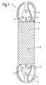
- Figs. 1 to 3 show a typical mandrel arrangement for a cross flow cross corrugated heat exchanger and preferred design features of mandrels and shells manufactured in accordance with aspects of the present invention.
- the example design is particularly suitable for a very lightweight air to air heat exchanger for use on an aero engine.
- Fig. 1 provides a view of a mandrel 1 for an electro formed shell as part of a cross-corrugated heat exchanger.
- the shell as indicated above, is generally formed from an electrically conductive material or from a base material which is coated with an electrically conductive material.
- a number of shells 1 will be produced to allow a stack to be formed and then secured together in association in order to create the heat exchanger.
- Particular features of the mandrel and therefore the shell include a tool hole or attachment point 2 for an electrical connection in an electro plating bath in order to create a shell upon a mandrel 1.
- Dimples 3 are provided in order to provide a location feature for reference or register with regard to subsequent machining of either the mandrel 1 as formed or an electro plated shell formed upon the mandrel 1 by plating or deposition.
- the mandrel 1 includes a number of flat surface areas 4 which will facilitate within the electro formed shell the ability to create brazing or diffusion bonding between the shells in a stack in order to create association and to form a heat exchanger.
- the mandrel 1 and therefore the electro formed shell formed upon the mandrel 1 will include diagonal grooves with a depth which will typically be almost half the thickness of the mandrel 1 in order to create respective cross flow passages in a heat exchanger for lower pressure resistance in a finally formed heat exchanger. It will be understood that similar grooves will be formed in the rear surface of the mandrel 1.
- the grooves 5 as indicated above in Fig. 1 are diagonal but it will be appreciated that other orientations of the grooves may be provided particularly with regard to determining the desired cross angles between respective flow path passages in layers of a finally formed heat exchanger.
- a small hole or aperture 6 may be provided within the mandrel 1 where some or all of the grooves on opposite faces intersect.
- the mandrel 1 may also include larger through holes 7 which can provide various association features in terms of fluid distribution within a final heat exchanger or provide registration for machining purposes.
- the mandrel 1 may also include brace areas 8 which will act to support and keep separate other parts of the mandrel during electro forming of a heat exchanger shell. These brace areas will typically be cut away once the shell has been formed in order to create the heat exchanger. Typically, part of the mandrel 1 will be utilised in order to create through electro forming the walls 9 of an integral manifold in a final heat exchanger comprising a stack of electro formed heat exchanger shells secured together. The manifold sections or walls 9 are brazed or otherwise secured together in order to create a manifold from one or more of the through holes 7.
- Fig. 2 provides a more detailed illustration of part of the mandrel 1 depicted in Fig. 1 .
- the mandrel 1 will create a heat exchanger shell by electro forming which will reflect the mandrel 1 shape.
- a dimple 3 or other feature is used to allow registration and association of the electro formed heat exchanger shell for subsequent machining processes along with location relative to other shells in a stack and the hole 7 may create through a wall portion 9 a manifold for the heat exchanger.
- Fig. 2 Of particular interest in Fig. 2 is the creation of grooves or corrugations 5 on either side of the mandrel 1. It will be noted that the grooves 5 are diagonal but respectively grooves 5a, 5b on each side of the mandrel 1 are substantially perpendicular to each other but the desired angle may typically range from 75° to 105°. At locations of cross over between the grooves 5a, 5b holes or apertures 6 are provided.
- edge 10 all external edges such as edge 10 except those for tooling holes will be smoothly rounded off. Such smoothing is desirable in order to achieve uniform material deposition in order to create heat exchanger shells of the desired thickness and integrity for forming a heat exchanger in accordance with aspects of the present invention.
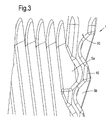
- Fig. 3 provides an edge 10 perspective view of the mandrel 1 depicted in Figs. 1 and 2 .
- the edge 10 develops into grooves 5a, 5b which as described previously are arranged diagonally and to cross at various positions at a desired angle. In such circumstances the edge 10 is generally wavy in the region of the grooves 5a, 5b but as indicated above is generally smooth in order to provide uniform material deposition upon the mandrel 1.
- the processes of electro forming and electro-less deposition are well known and it will be appreciated in such circumstances the mandrel 1 will be located within an appropriate plating bath incorporating an electrolyte.
- an electrical current through the mandrel 1 it will be understood that there will be deposition of a material such as copper upon the mandrel 1 in order to create the electro formed heat exchanger shells in accordance with aspects of the present invention.
- Such an approach enables cross flow designs and thinner plates with deeper corrugations to eliminate many of the bonded joints - increasing the effective surface area of the heat exchanger and it opens up the possibility of more sophisticated heat transfer surface geometries. Because the flattened shells can be manufactured with rounded edges, and with more complex profiles than a simple pressed sheet, the entry and exit losses for an open sided cross flow matrix can be significantly reduced.
- thermo hydraulic performance volume goodness and area goodness
- volume goodness and area goodness of a cross corrugated primary surface heat exchanger matrix, having intersection angles of around 90 degrees between the corrugations and suitable for a cross flow design, is greatly improved by having deeper corrugations of typically 2.2 or less pitch to depth ratio. Deeper corrugations will also result in a stiffer structure for a given density and one that is less prone to buckling on compression. Conversely, they can provide a lighter structure for a given strength, because thinner sections can be used.
- the previous plate cross corrugated heat exchangers and some other proposed matrix designs use shallower corrugations. One reason for this is that it is difficult to produce deep corrugations in a flat sheet simply by pressing.
- a pitch to depth ratio of 2.2 requires an average elongation of about 40%, which is not practical for most materials. Folding can produce deeper corrugations, but then these corrugations will need to be ironed out at the edges of the plates so that the edges of the plates can be joined together and sealed. This is a difficult and labour intensive process that requires special machinery, such as that described in US patent 4434637 .
- the example provided above is generally of an open sided cross flow heat exchanger with electro formed heat exchangers shells secured together to create one set of integral manifolds.
- the same principles can be used to manufacture a counter flow or parallel flow heat exchanger, optionally with two or more pairs of integral manifolds.
- a first fluid may reside in the interstices between the shells containing a second fluid, or alternatively each fluid may be contained within its own set of shells.
- the latter arrangement would be particularly advantageous in a heat exchanger where it is necessary to ensure that one fluid can never contaminate the other and the heat exchanger needs to be provided with a "tell tale" drains system to show up any leaks.
- the heat exchanger may be configured for use with more than two fluid streams.
- the heat exchanger may also be a hybrid design that incorporates secondary heat transfer surfaces on one or more flow sides, typically this will be the side with the lower density fluid.
- the electro formed shells may be clamped together rather than being permanently bonded. Their inherent flexibility can be used to provide a good seal between adjacent shells, with or without separate gaskets.
- heat exchangers in accordance with aspects of the present invention are quite compact and lightweight relative to other heat exchanger designs such that they have particular suitability in weight sensitive applications or other situations such as with automotive or auto sport applications.
- heat exchangers formed by heat exchanger shells in accordance with aspects of the present invention are not limited to air to air heat exchangers, even though they are particularly suitable for such applications.
- a heat exchanger can be provided.
- electro forming of the shells which create the heat exchanger can allow variation in shell thickness without limitations with regard to pressing processes. In such circumstances the thickness of the respective shells can be reduced in comparison with pressed shells and heat exchanger weight adjusted and typically lowered accordingly.
- the overall heat exchanger structure it may be possible, through appropriate techniques with regard to conduction, insulation and adjustment of electrical current flow through the mandrel, and auxiliary electrode placed around the mandrel to define a relatively thick skeleton structure for the heat exchanger shell with thinner wall sections between that skeleton or web reinforcement. This may again reduce the weight of the heat exchanger shell and therefore the stack formed as an overall heat exchanger.
- features such as apertures can be formed in this way
- Methods of forming heat exchangers in accordance with the present invention will include initially defining the mandrel upon which through electro forming the heat exchanger shells will be formed. Typically, as indicated above, these mandrels will be injection moulded with smooth surfaces where required. The mandrels may be reusable or removable as required. In either event it will be understood that the electro formed heat exchanger shell must be detached from the mandrel at some stage. In such circumstances the mandrel will typically include areas which can be removed in order to allow detachment or otherwise separation of the mandrel from the formed shell. Initial design of the mandrel is therefore important in order to create the desired heat exchanger shell geometry for combination in a stack as a heat exchanger.
- the electro forming process to create the heat exchanger shell as well as features necessary in order to create that shell and removal of the shell from the mandrel are known.
- the mandrel must be submersed in an electro plating bath and therefore a tool or method of suspending the mandrel in that bath must be provided along with a means for providing an electrical coupling to the mandrel.
- a tool or method of suspending the mandrel in that bath must be provided along with a means for providing an electrical coupling to the mandrel.
- the mandrel may create non reentrant heat exchanger shells such that flow paths are created by adjacent shells in the stack forming the heat exchanger.
- a mandrel may create a heat exchanger shell which is essentially a hollow structure with the mandrel in the centre and electro forming over the whole surface of the mandrel. In such circumstances the mandrel must be removed and generally this will be achieved through melting, burning, erosion or etching to leave the hollow structure which can then be assembled in a stack to form the heat exchanger.
- the mandrel may incorporate features which have a non or reduced electrically conductive nature in order to vary the shell thickness as required. It will also be understood that positioning of the electrodes may adjust the effectiveness of electro forming and therefore shell thickness as required. Typically an appropriate number of electrodes (anodes) electrically connected to the mandrel will be disposed so as to achieve the desired shell thickness. Mandrel removal may be through melting, evaporation, burning or etching but care must be taken, as the shell will generally be of a thin nature, to avoid distortions within that shell which may result in malformation of the stack and therefore eventual heat exchanger.
- mandrels will be arranged in order that heat exchanger shells are created in pairs which can then be associated together in order to define flow paths and channels through an eventual heat exchanger stack.
- respective heat exchanger shells may incorporate dimples or other features to achieve registration and reference. These dimples will also provide a reference for machining of the respective shells as required subsequent to formation on the mandrel.
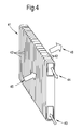
- FIG. 4 provides a schematic illustration of a heat exchanger 41 comprising a number of heat exchanger shells 42 formed into a stack.
- the shells 42 are electro formed upon mandrels as described above and associated appropriately by contacting junctions between parts of the shells 42 or pressed together with bolts (not shown).
- the heat exchanger 41 has a first inlet 43 and outlet 44 pair for a first fluid X and a second inlet 45 and outlet 46 pair for a second fluid Y so that there is cross flow and heat exchange between the fluids X, Y.
Landscapes
- Engineering & Computer Science (AREA)
- Mechanical Engineering (AREA)
- Physics & Mathematics (AREA)
- Thermal Sciences (AREA)
- General Engineering & Computer Science (AREA)
- Chemical & Material Sciences (AREA)
- Chemical Kinetics & Catalysis (AREA)
- Electrochemistry (AREA)
- Materials Engineering (AREA)
- Metallurgy (AREA)
- Organic Chemistry (AREA)
- Heat-Exchange Devices With Radiators And Conduit Assemblies (AREA)
Applications Claiming Priority (1)
| Application Number | Priority Date | Filing Date | Title |
|---|---|---|---|
| GBGB0715979.1A GB0715979D0 (en) | 2007-08-15 | 2007-08-15 | Heat exchanger |
Publications (3)
| Publication Number | Publication Date |
|---|---|
| EP2025427A2 true EP2025427A2 (fr) | 2009-02-18 |
| EP2025427A3 EP2025427A3 (fr) | 2009-04-22 |
| EP2025427B1 EP2025427B1 (fr) | 2010-11-10 |
Family
ID=38566484
Family Applications (1)
| Application Number | Title | Priority Date | Filing Date |
|---|---|---|---|
| EP08252456A Not-in-force EP2025427B1 (fr) | 2007-08-15 | 2008-07-18 | Procédé pour réaliser un échangeur de chaleur et échangeur de chaleur |
Country Status (5)
| Country | Link |
|---|---|
| US (2) | US8387248B2 (fr) |
| EP (1) | EP2025427B1 (fr) |
| KR (1) | KR101455136B1 (fr) |
| DE (1) | DE602008003361D1 (fr) |
| GB (1) | GB0715979D0 (fr) |
Cited By (3)
| Publication number | Priority date | Publication date | Assignee | Title |
|---|---|---|---|---|
| EP2405033A1 (fr) * | 2010-07-07 | 2012-01-11 | Moltex Co | Coque électroformée poreuse pour son procédé de formation et de fabrication |
| EP2599897A4 (fr) * | 2010-07-30 | 2015-09-02 | Donghwa Entec Co Ltd | Procédé de production pour un échangeur de chaleur à plaques |
| WO2019020530A1 (fr) | 2017-07-27 | 2019-01-31 | Fdx Fluid Dynamix Gmbh | Dispositif échangeur de chaleur |
Families Citing this family (13)
| Publication number | Priority date | Publication date | Assignee | Title |
|---|---|---|---|---|
| JP2005513403A (ja) * | 2001-12-21 | 2005-05-12 | ベール ゲーエムベーハー ウント コー カーゲー | 特に自動車用の熱交換器 |
| IT1399277B1 (it) * | 2009-08-03 | 2013-04-11 | Sis Ter Spa | Circuito di scambio termico. |
| EP2964911B1 (fr) | 2013-03-04 | 2022-02-23 | Echogen Power Systems LLC | Systèmes de moteur thermique possédant des circuits de dioxyde de carbone supercritique à haute énergie nette |
| US10837717B2 (en) * | 2013-12-10 | 2020-11-17 | Swep International Ab | Heat exchanger with improved flow |
| WO2016073252A1 (fr) | 2014-11-03 | 2016-05-12 | Echogen Power Systems, L.L.C. | Gestion de poussée active d'une turbopompe à l'intérieur d'un circuit de circulation de fluide de travail supercritique dans un système de moteur thermique |
| US11536521B2 (en) | 2018-02-23 | 2022-12-27 | Unison Industries, Llc | Heat exchanger assembly with a manifold additively manufactured onto a core and method of forming |
| US11187112B2 (en) | 2018-06-27 | 2021-11-30 | Echogen Power Systems Llc | Systems and methods for generating electricity via a pumped thermal energy storage system |
| US11435120B2 (en) | 2020-05-05 | 2022-09-06 | Echogen Power Systems (Delaware), Inc. | Split expansion heat pump cycle |
| US11629638B2 (en) | 2020-12-09 | 2023-04-18 | Supercritical Storage Company, Inc. | Three reservoir electric thermal energy storage system |
| US20220282391A1 (en) * | 2021-03-04 | 2022-09-08 | Unison Industries, Llc | Additive heat exchanger and method of forming |
| US11926006B2 (en) | 2021-03-17 | 2024-03-12 | Raytheon Company | Component manufacture and external inspection |
| US12516855B2 (en) | 2022-10-27 | 2026-01-06 | Supercritical Storage Company, Inc. | High-temperature, dual rail heat pump cycle for high performance at high-temperature lift and range |
| AU2024289421A1 (en) | 2023-02-07 | 2025-09-11 | Supercritical Storage Company, Inc. | Waste heat integration into pumped thermal energy storage |
Citations (2)
| Publication number | Priority date | Publication date | Assignee | Title |
|---|---|---|---|---|
| GB1063098A (en) | 1964-06-03 | 1967-03-30 | Herbert Fernyhough Maddocks | Improvements in heat exchangers |
| US4434637A (en) | 1980-01-28 | 1984-03-06 | Caterpillar Tractor Co. | Method and apparatus for flattening corrugated heat exchanger plate |
Family Cites Families (30)
| Publication number | Priority date | Publication date | Assignee | Title |
|---|---|---|---|---|
| US2540805A (en) * | 1946-04-30 | 1951-02-06 | John C Schwartz | Electrolytic apparatus for making radiator cores |
| US3258832A (en) * | 1962-05-14 | 1966-07-05 | Gen Motors Corp | Method of making sheet metal heat exchangers |
| US3308879A (en) * | 1964-06-10 | 1967-03-14 | Maddocks Herbert Fernyhough | Heat exchangers |
| US3364548A (en) * | 1964-12-08 | 1968-01-23 | Alex A. Marco | Method for producing an electroformed heat exchanger |
| GB1115988A (en) * | 1965-11-03 | 1968-06-06 | Herbert Fernyhough Maddocks | Improvements in heat exchangers |
| US4011905A (en) * | 1975-12-18 | 1977-03-15 | Borg-Warner Corporation | Heat exchangers with integral surge tanks |
| US4249597A (en) * | 1979-05-07 | 1981-02-10 | General Motors Corporation | Plate type heat exchanger |
| DE3017515A1 (de) | 1980-05-07 | 1981-11-12 | Rudolf Ing. Mutters Zlotek sen. | Waermetauscher |
| US4727935A (en) * | 1985-05-13 | 1988-03-01 | Laitram Corporation | Heat exchanger and method for making same |
| US4871623A (en) * | 1988-02-19 | 1989-10-03 | Minnesota Mining And Manufacturing Company | Sheet-member containing a plurality of elongated enclosed electrodeposited channels and method |
| GB8910966D0 (en) * | 1989-05-12 | 1989-06-28 | Du Pont Canada | Panel heat exchangers formed from thermoplastic polymers |
| US5249358A (en) * | 1992-04-28 | 1993-10-05 | Minnesota Mining And Manufacturing Company | Jet impingment plate and method of making |
| FR2728666A1 (fr) * | 1994-12-26 | 1996-06-28 | Valeo Thermique Habitacle | Echangeur de chaleur a trois fluides d'encombrement reduit |
| DE69702723T2 (de) * | 1996-02-05 | 2001-03-29 | Sanden Corp | Wärmetauscher hergestellt durch Hartlöten eines vorläufigen Zusammenbaus und Verfahren zu dessen Herstellung |
| US5871158A (en) * | 1997-01-27 | 1999-02-16 | The University Of Utah Research Foundation | Methods for preparing devices having metallic hollow microchannels on planar substrate surfaces |
| JP4122578B2 (ja) * | 1997-07-17 | 2008-07-23 | 株式会社デンソー | 熱交換器 |
| EP0935115B1 (fr) * | 1998-02-05 | 2003-07-09 | Denso Corporation | Echangeur de chaleur fabriqué avec plusieurs plaques conductrices de chaleur |
| US6401804B1 (en) * | 1999-01-14 | 2002-06-11 | Denso Corporation | Heat exchanger only using plural plates |
| DE10220532A1 (de) * | 2001-05-11 | 2002-11-14 | Behr Gmbh & Co | Wärmetauscher |
| DE20114850U1 (de) * | 2001-09-07 | 2003-01-16 | Behr Gmbh & Co, 70469 Stuttgart | Wärmetauscher |
| US6896043B2 (en) * | 2002-03-05 | 2005-05-24 | Telephonics Corporation | Heat exchanger |
| US20030196451A1 (en) * | 2002-04-11 | 2003-10-23 | Lytron, Inc. | Contact cooling device |
| SE0202747L (sv) * | 2002-09-17 | 2004-02-10 | Valeo Engine Cooling Ab | Anordning vid en plattvärmeväxlare |
| SE524176C2 (sv) * | 2002-11-01 | 2004-07-06 | Ep Technology Ab | Värmeväxlare med förstärkningsorgan |
| DE10322406A1 (de) * | 2003-05-16 | 2004-12-02 | Api Schmidt-Bretten Gmbh & Co. Kg | Platten-Wärmeübertrager |
| EP1692327A2 (fr) * | 2003-11-25 | 2006-08-23 | Media Lario S.r.L. | Fabrication de systemes de transfert de chaleur et de refroidissement par electroformage |
| JP2006010102A (ja) * | 2004-06-22 | 2006-01-12 | Sanden Corp | 積層型熱交換器およびその製造方法 |
| CN100582627C (zh) * | 2005-05-24 | 2010-01-20 | 达纳加拿大公司 | 多流体热交换器 |
| GB0605802D0 (en) | 2006-03-23 | 2006-05-03 | Rolls Royce Plc | A heat exchanger |
| SE530970C2 (sv) * | 2007-03-07 | 2008-11-04 | Airec Ab | Värmeväxlare av korsströmstyp |
-
2007
- 2007-08-15 GB GBGB0715979.1A patent/GB0715979D0/en not_active Ceased
-
2008
- 2008-07-18 EP EP08252456A patent/EP2025427B1/fr not_active Not-in-force
- 2008-07-18 DE DE602008003361T patent/DE602008003361D1/de active Active
- 2008-07-21 US US12/219,373 patent/US8387248B2/en not_active Expired - Fee Related
- 2008-08-14 KR KR1020080080055A patent/KR101455136B1/ko not_active Expired - Fee Related
-
2013
- 2013-02-04 US US13/758,252 patent/US20130186606A1/en not_active Abandoned
Patent Citations (2)
| Publication number | Priority date | Publication date | Assignee | Title |
|---|---|---|---|---|
| GB1063098A (en) | 1964-06-03 | 1967-03-30 | Herbert Fernyhough Maddocks | Improvements in heat exchangers |
| US4434637A (en) | 1980-01-28 | 1984-03-06 | Caterpillar Tractor Co. | Method and apparatus for flattening corrugated heat exchanger plate |
Cited By (4)
| Publication number | Priority date | Publication date | Assignee | Title |
|---|---|---|---|---|
| EP2405033A1 (fr) * | 2010-07-07 | 2012-01-11 | Moltex Co | Coque électroformée poreuse pour son procédé de formation et de fabrication |
| EP2599897A4 (fr) * | 2010-07-30 | 2015-09-02 | Donghwa Entec Co Ltd | Procédé de production pour un échangeur de chaleur à plaques |
| WO2019020530A1 (fr) | 2017-07-27 | 2019-01-31 | Fdx Fluid Dynamix Gmbh | Dispositif échangeur de chaleur |
| DE102017212961A1 (de) | 2017-07-27 | 2019-01-31 | Fdx Fluid Dynamix Gmbh | Fluidisches Bauteil |
Also Published As
| Publication number | Publication date |
|---|---|
| US8387248B2 (en) | 2013-03-05 |
| US20130186606A1 (en) | 2013-07-25 |
| KR20090018002A (ko) | 2009-02-19 |
| GB0715979D0 (en) | 2007-09-26 |
| DE602008003361D1 (de) | 2010-12-23 |
| US20090044933A1 (en) | 2009-02-19 |
| KR101455136B1 (ko) | 2014-10-27 |
| EP2025427B1 (fr) | 2010-11-10 |
| EP2025427A3 (fr) | 2009-04-22 |
Similar Documents
| Publication | Publication Date | Title |
|---|---|---|
| EP2025427B1 (fr) | Procédé pour réaliser un échangeur de chaleur et échangeur de chaleur | |
| KR100436908B1 (ko) | 플레이트식 열교환기 및 그 제조방법 | |
| AU638132B2 (en) | Heat exchangers | |
| US5465484A (en) | Heat exchanger | |
| CN107427920A (zh) | 用于板式热交换器的3d打印加热表面元件 | |
| KR20150040376A (ko) | 열 교환기 및 제작 방법 | |
| WO2008079679A2 (fr) | Procédé de production d'échangeur de chaleur | |
| US9406948B2 (en) | Electroformed bipolar plates for fuel cells | |
| CN117651646A (zh) | 共烧结 | |
| US4807342A (en) | Method for making an improved heat exchanger | |
| JP2013532811A (ja) | プレート式熱交換器の製造方法 | |
| US8347503B2 (en) | Methods of manufacturing brazed aluminum heat exchangers | |
| US4727935A (en) | Heat exchanger and method for making same | |
| JP4482997B2 (ja) | 積層式熱交換器およびその製造方法 | |
| JP2025531925A (ja) | 熱交換器モジュール | |
| JPH01247991A (ja) | 熱交換器およびその製造方法 | |
| EP4023992B1 (fr) | Échangeur de chaleur | |
| JPH1163880A (ja) | 積層式熱交換器の製造方法 | |
| CN121844177A (zh) | 通过叠层实体制造法制造的换热器和冷板 | |
| WO2026090188A1 (fr) | Échangeurs de chaleur métalliques à joints de dilatation thermique | |
| JP2000356491A (ja) | プレート式熱交換器 | |
| JPH04324030A (ja) | ガスタービン燃焼器 | |
| CN117870413A (zh) | 由两种类型的板材制成的热交换器 | |
| KR20260031908A (ko) | 판형 열교환기 및 그 제조방법 | |
| CN121285722A (zh) | 热交换器和具有其的空调机 |
Legal Events
| Date | Code | Title | Description |
|---|---|---|---|
| PUAI | Public reference made under article 153(3) epc to a published international application that has entered the european phase |
Free format text: ORIGINAL CODE: 0009012 |
|
| AK | Designated contracting states |
Kind code of ref document: A2 Designated state(s): AT BE BG CH CY CZ DE DK EE ES FI FR GB GR HR HU IE IS IT LI LT LU LV MC MT NL NO PL PT RO SE SI SK TR |
|
| AX | Request for extension of the european patent |
Extension state: AL BA MK RS |
|
| PUAL | Search report despatched |
Free format text: ORIGINAL CODE: 0009013 |
|
| AK | Designated contracting states |
Kind code of ref document: A3 Designated state(s): AT BE BG CH CY CZ DE DK EE ES FI FR GB GR HR HU IE IS IT LI LT LU LV MC MT NL NO PL PT RO SE SI SK TR |
|
| AX | Request for extension of the european patent |
Extension state: AL BA MK RS |
|
| RIC1 | Information provided on ipc code assigned before grant |
Ipc: F28F 3/02 20060101ALI20090318BHEP Ipc: B21D 53/02 20060101ALI20090318BHEP Ipc: F28D 1/03 20060101AFI20090318BHEP Ipc: C25D 1/02 20060101ALI20090318BHEP Ipc: F28F 3/04 20060101ALI20090318BHEP |
|
| 17P | Request for examination filed |
Effective date: 20091020 |
|
| 17Q | First examination report despatched |
Effective date: 20091113 |
|
| AKX | Designation fees paid |
Designated state(s): DE FR GB |
|
| GRAP | Despatch of communication of intention to grant a patent |
Free format text: ORIGINAL CODE: EPIDOSNIGR1 |
|
| GRAS | Grant fee paid |
Free format text: ORIGINAL CODE: EPIDOSNIGR3 |
|
| GRAA | (expected) grant |
Free format text: ORIGINAL CODE: 0009210 |
|
| AK | Designated contracting states |
Kind code of ref document: B1 Designated state(s): DE FR GB |
|
| REG | Reference to a national code |
Ref country code: GB Ref legal event code: FG4D |
|
| REF | Corresponds to: |
Ref document number: 602008003361 Country of ref document: DE Date of ref document: 20101223 Kind code of ref document: P |
|
| PLBE | No opposition filed within time limit |
Free format text: ORIGINAL CODE: 0009261 |
|
| STAA | Information on the status of an ep patent application or granted ep patent |
Free format text: STATUS: NO OPPOSITION FILED WITHIN TIME LIMIT |
|
| 26N | No opposition filed |
Effective date: 20110811 |
|
| REG | Reference to a national code |
Ref country code: DE Ref legal event code: R097 Ref document number: 602008003361 Country of ref document: DE Effective date: 20110811 |
|
| PGFP | Annual fee paid to national office [announced via postgrant information from national office to epo] |
Ref country code: GB Payment date: 20120719 Year of fee payment: 5 |
|
| PGFP | Annual fee paid to national office [announced via postgrant information from national office to epo] |
Ref country code: DE Payment date: 20120720 Year of fee payment: 5 Ref country code: FR Payment date: 20120806 Year of fee payment: 5 |
|
| GBPC | Gb: european patent ceased through non-payment of renewal fee |
Effective date: 20130718 |
|
| REG | Reference to a national code |
Ref country code: DE Ref legal event code: R119 Ref document number: 602008003361 Country of ref document: DE Effective date: 20140201 |
|
| REG | Reference to a national code |
Ref country code: FR Ref legal event code: ST Effective date: 20140331 |
|
| PG25 | Lapsed in a contracting state [announced via postgrant information from national office to epo] |
Ref country code: GB Free format text: LAPSE BECAUSE OF NON-PAYMENT OF DUE FEES Effective date: 20130718 Ref country code: DE Free format text: LAPSE BECAUSE OF NON-PAYMENT OF DUE FEES Effective date: 20140201 |
|
| PG25 | Lapsed in a contracting state [announced via postgrant information from national office to epo] |
Ref country code: FR Free format text: LAPSE BECAUSE OF NON-PAYMENT OF DUE FEES Effective date: 20130731 |