EP2025436A2 - Plaquette de coupe - Google Patents
Plaquette de coupe Download PDFInfo
- Publication number
- EP2025436A2 EP2025436A2 EP08020126A EP08020126A EP2025436A2 EP 2025436 A2 EP2025436 A2 EP 2025436A2 EP 08020126 A EP08020126 A EP 08020126A EP 08020126 A EP08020126 A EP 08020126A EP 2025436 A2 EP2025436 A2 EP 2025436A2
- Authority
- EP
- European Patent Office
- Prior art keywords
- cutting
- inserts
- cutting edge
- plate
- hard material
- Prior art date
- Legal status (The legal status is an assumption and is not a legal conclusion. Google has not performed a legal analysis and makes no representation as to the accuracy of the status listed.)
- Withdrawn
Links
Images


Classifications
-
- B—PERFORMING OPERATIONS; TRANSPORTING
- B23—MACHINE TOOLS; METAL-WORKING NOT OTHERWISE PROVIDED FOR
- B23B—TURNING; BORING
- B23B27/00—Tools for turning or boring machines; Tools of a similar kind in general; Accessories therefor
- B23B27/14—Cutting tools of which the bits or tips or cutting inserts are of special material
- B23B27/141—Specially shaped plate-like cutting inserts, i.e. length greater or equal to width, width greater than or equal to thickness
- B23B27/145—Specially shaped plate-like cutting inserts, i.e. length greater or equal to width, width greater than or equal to thickness characterised by having a special shape
-
- B—PERFORMING OPERATIONS; TRANSPORTING
- B02—CRUSHING, PULVERISING, OR DISINTEGRATING; PREPARATORY TREATMENT OF GRAIN FOR MILLING
- B02C—CRUSHING, PULVERISING, OR DISINTEGRATING IN GENERAL; MILLING GRAIN
- B02C18/00—Disintegrating by knives or other cutting or tearing members which chop material into fragments
- B02C18/06—Disintegrating by knives or other cutting or tearing members which chop material into fragments with rotating knives
- B02C18/16—Details
- B02C18/18—Knives; Mountings thereof
- B02C18/186—Axially elongated knives
-
- B—PERFORMING OPERATIONS; TRANSPORTING
- B23—MACHINE TOOLS; METAL-WORKING NOT OTHERWISE PROVIDED FOR
- B23B—TURNING; BORING
- B23B27/00—Tools for turning or boring machines; Tools of a similar kind in general; Accessories therefor
- B23B27/10—Cutting tools with special provision for cooling
-
- B—PERFORMING OPERATIONS; TRANSPORTING
- B23—MACHINE TOOLS; METAL-WORKING NOT OTHERWISE PROVIDED FOR
- B23B—TURNING; BORING
- B23B2200/00—Details of cutting inserts
- B23B2200/16—Supporting or bottom surfaces
- B23B2200/165—Supporting or bottom surfaces with one or more grooves
-
- B—PERFORMING OPERATIONS; TRANSPORTING
- B23—MACHINE TOOLS; METAL-WORKING NOT OTHERWISE PROVIDED FOR
- B23B—TURNING; BORING
- B23B2200/00—Details of cutting inserts
- B23B2200/20—Top or side views of the cutting edge
- B23B2200/205—Top or side views of the cutting edge with cutting edge having a wave form
-
- B—PERFORMING OPERATIONS; TRANSPORTING
- B23—MACHINE TOOLS; METAL-WORKING NOT OTHERWISE PROVIDED FOR
- B23B—TURNING; BORING
- B23B2200/00—Details of cutting inserts
- B23B2200/36—Other features of cutting inserts not covered by B23B2200/04 - B23B2200/32
- B23B2200/3618—Fixation holes
-
- B—PERFORMING OPERATIONS; TRANSPORTING
- B23—MACHINE TOOLS; METAL-WORKING NOT OTHERWISE PROVIDED FOR
- B23B—TURNING; BORING
- B23B2210/00—Details of turning tools
- B23B2210/02—Tool holders having multiple cutting inserts
-
- B—PERFORMING OPERATIONS; TRANSPORTING
- B23—MACHINE TOOLS; METAL-WORKING NOT OTHERWISE PROVIDED FOR
- B23B—TURNING; BORING
- B23B2215/00—Details of workpieces
- B23B2215/60—Steel wool
-
- B—PERFORMING OPERATIONS; TRANSPORTING
- B23—MACHINE TOOLS; METAL-WORKING NOT OTHERWISE PROVIDED FOR
- B23B—TURNING; BORING
- B23B2222/00—Materials of tools or workpieces composed of metals, alloys or metal matrices
- B23B2222/21—Copper
-
- B—PERFORMING OPERATIONS; TRANSPORTING
- B23—MACHINE TOOLS; METAL-WORKING NOT OTHERWISE PROVIDED FOR
- B23C—MILLING
- B23C2200/00—Details of milling cutting inserts
- B23C2200/16—Supporting or bottom surfaces
- B23C2200/165—Supporting or bottom surfaces with one or more grooves
-
- B—PERFORMING OPERATIONS; TRANSPORTING
- B26—HAND CUTTING TOOLS; CUTTING; SEVERING
- B26D—CUTTING; DETAILS COMMON TO MACHINES FOR PERFORATING, PUNCHING, CUTTING-OUT, STAMPING-OUT OR SEVERING
- B26D1/00—Cutting through work characterised by the nature or movement of the cutting member or particular materials not otherwise provided for; Apparatus or machines therefor; Cutting members therefor
- B26D1/0006—Cutting members therefor
- B26D2001/0033—Cutting members therefor assembled from multiple blades
Definitions
- the invention relates to cutting plates for cutting tools.
- cutting inserts are made of alloyed steel, carbide or high-alloy powder metallurgy steel, or the like.
- blades which are clamped in special holders, are equipped with different serrations on the blade edge in order to "scrape" long fiber and different "steel wool wire fiber thicknesses” of steel wires according to the respective corrugation pitch.
- the respective desired faction (“steel wool-wire-fiber thickness") are separated from the steel wires according to the respective riffle division of the blade used.
- the invention has for its object a novel cutting plate for cutting tools to develop which has a very high cutting capacity (life) as a result of the invention, which significantly increases the life of these inserts and thus the maintenance and repair of the manufacturing facilities in which the inserts according to the invention
- the availability and thus the production capacity of the production equipment equipped with the novel cutting plates can be significantly increased, and which also due to the significantly improved cutting edge / tool life not only in cutting tools in the metal processing but also in cutting tools in disposal and recycling plants, for cutting tools of the mining and processing industry, for cutting tools of the paper and wood industry, for cutting tools of medical technology but also for cutting be used in the construction and food industries.
- this object is achieved by means of a cutting insert (1) made of alloyed steel, of hard metal, or of high-alloyed powder-metallurgically produced steel, or the like. with one or more cutting edges (6), these cutting edges (6) being formed either directly on the cutting plate (1) or on in Area of the cutting edge / s (6) on the cutting plate (1) fixed hard material / n (22) are arranged, achieved in that in the region of the cutting edge / s (6), ie either on the surface (3) of the cutting plates (1 ) or on the cutting edge (6) of the hard material strip / s (22), groove profiles (17) are arranged.
- the cutting inserts according to the invention therefore not only in cutting tools in the field of metal processing and cutting tools in disposal and recycling plants, cutting tools of the extraction and processing industry, cutting tools of the paper and wood industry, cutting tools in medical technology but also with cutting tools in the construction and the food industry can be used.
- the smaller inner radius (R2) at the tip of the pressing tool more easily penetrates into the powder mass and thereby causes a more uniform distribution of the powder mass in the groove bottom.
- the solution according to the invention has the effect that the inserts (1) made of cemented carbide can be produced automatically at low cost, whereby, of course, different carbide grades which are optimal for the respective application are used.
- the cutting plates (1) are designed as indexable inserts with two opposite cutting edges (6).
- inserts (1) designed as indexable inserts make it possible for even the cutting plates (1) worn on one of the two cutting edges (6) to be readjusted and re-aligned along the respective cutting edge (5) with the uncut cutting edge (6).
- the inventive design as indexable inserts not only doubles the service life of the individual inserts (1) but also causes even different groove profiles, such as different sizes of groove profiles and / or different groove inclinations ( ⁇ ) relative to the cutting edge, for a variety of applications on the two opposite cutting edges (6) of a cutting plate (1) can be arranged.
- the groove profile (17) to the cutting edge (6) is arranged at a groove inclination angle ⁇ from 0 ° to 180 °.
- the invention also provides that the groove profile (17) is arranged crosswise to the cutting edge (6), for example at a groove inclination angle ( ⁇ ) of 45 °.
- Such a groove profile (17) is very well suited, for example, for the comminution of different woods, but also for the comminution of long-fiber wood and also for crushing particleboard or similar materials, since by means of such profiling of these materials small chips are generated whereby a " Blockage "of the plant can be counteracted.
- the cutting inserts (1) according to the invention make it possible for cutting plates (1) to be juxtaposed with different cutting edges (6), for example, along one tool cutting edge (5).
- different sizes of a groove profile (17) can be arranged.
- a further feature of the invention is that a hard material layer is arranged on the respective cutting edge (s) (6) in the cutting inserts (1) according to the invention with only one cutting edge (6), but also in the cutting inserts (1) designed as indexable cutting inserts according to the invention.
- a hard material layer is arranged on the respective cutting edge (s) (6) in the cutting inserts (1) according to the invention with only one cutting edge (6), but also in the cutting inserts (1) designed as indexable cutting inserts according to the invention.
- the tool base body (2) carries a heat-conducting coating (18) at least on the bearing surface (9) of the cutting plate (1).
- this coating (18) consists of copper.
- This thermally conductive layer such as a copper layer is used for optimal heat dissipation from the cutting plates (1) in the tool body (2).
- the sticking tendency becomes the cutting edge (6), especially in the machining of stainless materials significantly reduced.
- one or, alternatively, two hard-material strips (22) according to the invention are soldered or glued on the cutting plate (1), which are respectively provided with the cutting edge (s) (6) equipped with groove profile (21).
- groove profiles 17 are incorporated in the area of the cutting edges 6 on the surface 3 of these cutting inserts 1 according to the invention.
- These groove profiles 17 are perpendicular to the cutting edge 6 and cause a very high cutting capacity (service life) of the tool cutting edge.
- the cutting plates 1 with the groove profile 17 according to the invention can, as in the FIG. 1 also shown, also be designed as inserts with two provided with a groove profiles 17 cutting 6.
- This version as a turning plate allows not only a doubling of the service life of the inserts 1 but also at the same time that different sizes of groove profiles 17 can be arranged on a cutting plate 1.
- a heat-conductive coating 18 is disposed of copper on the support surface 9 of the insert 1.
- This heat-conducting copper layer serves for optimum dissipation of the heat generated in the cutting process from the cutting plates 1 into the tool base body 2.
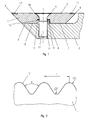
- FIG. 2 now shows a partial section through the groove profile 17 of a cutting insert 1 made of hard metal.
- Such cutting inserts made of hard metal can be produced automatically, ie both press automatically as well as automatically grind.
- the outer radius R1 of the incorporated on the surface of the cutting plate 1 groove profile 17 is greater than the inner radius R2.
- the arranged at the top of the pressing tool smaller radius R2 penetrates more easily into the powder mass, and thus contributes to a more even distribution in the groove bottom.
- Another feature of the invention is that the spacing of the grooves of the groove profile, ie the pitch T across the width of the tool cutting edge 5, but also, the pitch T on the cutting edge 6 within a cutting plate 1 may be uneven.
- Such embodiments are primarily used in the construction industry, but also in the DIY sector as a scraper for paint residues or other impurities.
- Scrapers with the inserts 1 according to the invention allow a lightweight construction and can be both provided with a handle, or arranged by means of an adapter on a vibrating device, or combined with a high-pressure cleaner.
- FIG. 4 shows the top view of an equipped with inserts 1 tool body 2, in the present case an asymmetrically equipped with seven inserts cutting bar a recycling plant.
- the cutting inserts 1 used in this case consist of a high-alloyed powder-metallurgically produced steel.
- FIG. 5 shows the top view of the cutting tool 5 a cutting bar for biomass arranged on the cutting plates 1 soldered on one side, provided with the groove profile 17 according to the invention hard material strips 22nd
- the cutting inserts 1 can also be exchanged individually with the hard material strips 22 according to the invention in this embodiment as well.
- FIG. 6 now shows the partial section at AA by in the FIG. 5 shown cutting strip for biomass with a soldered on one side in the inserts 1 hard material strip according to the invention 22, ie with a arranged in this hard material strip 22 in the region of the cutting edge 6 groove profile 17th
- FIG. 7 is now a partial section through a usable as a turning insert 1 with both sides glued in accordance with the invention, ie provided in the region of the cutting edge 6 with the groove profile 17 hard material strips 22.
- FIG. 8 shows the top view of the section of a tool cutting edge 5 of cutting inserts 1 according to the invention with hard strips 22 arranged on both sides and a groove profile 17 arranged perpendicular to the cutting edge 6 in the hard strips 22.
- This groove profile which is arranged perpendicularly to the cutting edge 6 and has a groove inclination angle ⁇ of 90 °, is effective even in the case of long-chipping materials, such as, for example, for Cu, Mg, Al and their alloys a secured chip breakage.
- FIG. 9 Another possible embodiment of the hard material strips 22 to be arranged on cutting plates 1 is shown with groove profile 17 arranged parallel to the cutting edge 6. This parallel to the cutting edge 6 arranged groove profile 17 with a groove inclination angle ⁇ of 180 ° is also well suited for the crushing of cardboard of different thickness.
- FIG. 10 shows a further possible embodiment of the solution according to the invention with an obliquely arranged to the cutting edge 6 groove profile 17, here especially with a groove inclination angle ⁇ of 30 °.
- Such a groove profile 17 with a groove inclination angle ⁇ of 30 ° with respect to the cutting edge 6 is very well suited for steel wool production, in the context of steel wool production even a much lower groove inclination already ensures a deflection of the cutter bar for take-up, so that disturbances and downtime can be avoided.
- FIG. 11 shows a further possible embodiment of the solution according to the invention with a crosswise to the cutting edge 6 arranged groove profile 17, here with a groove inclination angle ⁇ of 45 ° with respect to the cutting edge.
- inventive groove profile 17 is very well suited for the comminution of different woods, even for crushing long-fiber wood, but also for crushing particleboard or similar materials, since by means of such profiling of these materials small chips are generated whereby a "blockage" of System is counteracted.
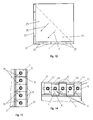
- FIG. 12 shows the front view of a "cutting tooth".
- Such cutting teeth are disposed on rotors of recycling and processing machines which are also capable of rotating at speeds of from 200 rpm to 4000 rpm. Taking into account the resulting during the crushing process Heat the bearing clearances are chosen larger, which inevitably increased vibrations result in increased stress and consequent increased wear of the cutting teeth.
- the inserts are arranged "upright" in this application.
- This particular arrangement according to the invention with frontal, almost frontal load allows a much higher load capacity as well as a resulting from this arrangement much higher stability with a related lower risk of breakage and thus provides on the flanks of the front side of the cutting teeth a very high wear protection.
- the tooth flanks 20 are formed by five inserts 1.
- the tooth surface 25 lying between these tooth flanks 20 is coated with tungsten carbide powder in the direction of the tooth tip 21, so that during use, i. when recycling the form of the armor leads to an additional "tearing" effect, while minimizing the wear of the tooth surface 25 between the tooth flanks 20.
- FIG. 14 now shows the top view of a likewise possible according to the invention embodiment of the tooth flank of the cutting tooth FIG. 12 , namely with along each tooth flank 20 offset in depth arranged cutting plates. 1
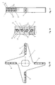
- FIG. 15 is the side view of a four-armed, occupied with the inserts according to the invention in rows, cutting both sides cutting shear knife for biomass shown which operates between two perforated discs, so that the opposing cutting edges are always in use simultaneously.
- FIG. 16 shows in plan view one of the two-sided cutting, equipped with the groove profile according to the invention 17 cutting plate rows.
- FIG. 17 is now the top view of the insert row of a similar to the FIG. 15 trained Schermessers for biomass, but with laterally arranged alternately, provided with the groove profile 17 according to the invention, the cutting edge 5 forming cutting plates 1 shown.
- this embodiment which also operates between two perforated discs, alternately one provided with the groove profile 17 according to the invention tool cutting edge 5 is used.
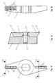
- FIG. 18 now shows the side view of a two-armed, with the cutting inserts 1 according to the invention in series, one-sided cutting shear blade for biomass but which works on only one perforated disc.
- FIG. 19 is now the section at AA through one of the cutting edges of the two-armed, according to invention, ie provided with the groove profile 17 according to the invention cutting inserts 1 occupied, unilaterally cutting shearing blade for biomass according to FIG. 18 shown.
- FIG. 20 shows the top view of the arranged with the groove profile 17 according to the invention in series inserts 1 of the two-armed, one-side cutting shear blade for biomass according to FIG. 18 ,
Landscapes
- Engineering & Computer Science (AREA)
- Food Science & Technology (AREA)
- Mechanical Engineering (AREA)
- Crushing And Pulverization Processes (AREA)
- Milling Processes (AREA)
- Knives (AREA)
Applications Claiming Priority (2)
| Application Number | Priority Date | Filing Date | Title |
|---|---|---|---|
| DE102005007676A DE102005007676B3 (de) | 2005-02-19 | 2005-02-19 | Anordnung und Befestigung von Schneidplatten |
| EP06002597A EP1693132A1 (fr) | 2005-02-19 | 2006-02-09 | Système de montage de plaquettes de coupe |
Related Parent Applications (1)
| Application Number | Title | Priority Date | Filing Date |
|---|---|---|---|
| EP06002597A Division EP1693132A1 (fr) | 2005-02-19 | 2006-02-09 | Système de montage de plaquettes de coupe |
Publications (2)
| Publication Number | Publication Date |
|---|---|
| EP2025436A2 true EP2025436A2 (fr) | 2009-02-18 |
| EP2025436A3 EP2025436A3 (fr) | 2009-09-02 |
Family
ID=36353657
Family Applications (2)
| Application Number | Title | Priority Date | Filing Date |
|---|---|---|---|
| EP06002597A Withdrawn EP1693132A1 (fr) | 2005-02-19 | 2006-02-09 | Système de montage de plaquettes de coupe |
| EP08020126A Withdrawn EP2025436A3 (fr) | 2005-02-19 | 2006-02-09 | Plaquette de coupe |
Family Applications Before (1)
| Application Number | Title | Priority Date | Filing Date |
|---|---|---|---|
| EP06002597A Withdrawn EP1693132A1 (fr) | 2005-02-19 | 2006-02-09 | Système de montage de plaquettes de coupe |
Country Status (2)
| Country | Link |
|---|---|
| EP (2) | EP1693132A1 (fr) |
| DE (1) | DE102005007676B3 (fr) |
Cited By (1)
| Publication number | Priority date | Publication date | Assignee | Title |
|---|---|---|---|---|
| WO2015193249A1 (fr) * | 2014-06-18 | 2015-12-23 | Betek Gmbh & Co. Kg | Contre-lame |
Families Citing this family (11)
| Publication number | Priority date | Publication date | Assignee | Title |
|---|---|---|---|---|
| EP2204251A1 (fr) * | 2008-12-31 | 2010-07-07 | VARGUS Ltd. | Support d'outil pour outil de découpe et outil de découpe |
| US8857748B2 (en) | 2011-11-17 | 2014-10-14 | Kennametal Inc. | Grinding tool |
| DE102012007193B4 (de) * | 2012-04-12 | 2016-06-23 | Karl Eugen Fischer Gmbh | Schneidmesser sowie Stahlcordschere umfassend ein solches Schneidmesser |
| US9370776B2 (en) | 2013-04-29 | 2016-06-21 | Vermeer Manufacturing Company | Mounting block for attaching a reducing element to a rotary drum |
| NL2021389B1 (en) * | 2018-07-24 | 2020-01-30 | Vmi Holland Bv | Round knife, cutting assembly and method for cutting tire components |
| DE102018126283A1 (de) | 2018-10-23 | 2020-04-23 | Bayerische Motoren Werke Aktiengesellschaft | Werkzeug zum Schneiden eines Werkstücks |
| DE102019133124A1 (de) * | 2019-12-05 | 2021-06-10 | Bayerische Motoren Werke Aktiengesellschaft | Werkzeug zum Schneiden von Blechbauteilen |
| CN111112659B (zh) * | 2020-01-09 | 2025-03-18 | 中国工程物理研究院化工材料研究所 | 一种用于加工含能材料的可调式多切削刃车削刀具 |
| CN111633153A (zh) * | 2020-06-04 | 2020-09-08 | 海纳川(滨州)轻量化汽车部件有限公司 | 预铸销剪切刀具和预铸销切断装置 |
| CN113560675A (zh) * | 2021-07-05 | 2021-10-29 | 张�杰 | 一种切削刀片及切削刀具 |
| CN120588396B (zh) * | 2025-07-10 | 2025-12-16 | 埃维恩(上海)机械有限公司 | 一种具备可调节刀刃的破碎机用切割棍 |
Family Cites Families (31)
| Publication number | Priority date | Publication date | Assignee | Title |
|---|---|---|---|---|
| DE7346110U (de) * | 1974-04-04 | Stahlwerke Roechling Burbach Gmbh | Werkzeug mit einem Hartmetalleinsatz zum Herstellen von Stahlfasern oder Stahlwolle | |
| US2365965A (en) * | 1941-12-30 | 1944-12-26 | Cutanit | Cutting tool |
| US3341920A (en) * | 1965-02-16 | 1967-09-19 | Gen Electric | Cutting tool |
| DE7102492U (de) * | 1971-01-23 | 1971-04-29 | Roechlingsche Eisen Und Stahlwerke Gmbh | Werkzeug mit einem hartmetalleinsatz zum herstellen von stahlfasern oder stahlwolle |
| IT990237B (it) * | 1972-08-15 | 1975-06-20 | Malinchak P | Perfezionamento negli inserti ta glienti per macchine per la lavora zione di metalli |
| DE2906148A1 (de) * | 1979-02-17 | 1980-08-28 | Walter Gmbh Montanwerke | Schneidwerkzeug mit wendeplattenbestueckung |
| IL60042A (en) * | 1979-05-16 | 1983-05-15 | De Beers Ind Diamond | Abrasive bodies |
| DE2936869C2 (de) * | 1979-09-12 | 1987-03-12 | Karl-Heinz Arnold, Hartmetallwerkzeuge-Großhandel, 7302 Ostfildern | Schneidwerkzeug für die spanabhebende Bearbeitung |
| IL58378A (en) * | 1979-10-03 | 1981-10-30 | Iscar Ltd | Tool holder for a single cutting insert |
| CH645287A5 (de) * | 1980-04-24 | 1984-09-28 | Herbert Deni | Wendeschneidplattenhalter. |
| EP0090037A1 (fr) * | 1981-10-02 | 1983-10-05 | GARDNER, James Joseph | Outil de coupe et dispositif d'assemblage d'outil |
| JPS59224222A (ja) * | 1983-06-03 | 1984-12-17 | Toyo Seisen Kk | 金属短繊維の製造方法 |
| DD234234A1 (de) * | 1985-01-02 | 1986-03-26 | Thueringer Fleischkombinat Ger | Kreuzmesser fuer fleischwoelfe insbesondere in der fleischindustrie mit hartmetallwendeschneidplattenbestueckung |
| US4871119A (en) * | 1987-03-06 | 1989-10-03 | Kabushiki Kaisha Kobe Seiko Sho | Impact crushing machine |
| DE4201112C2 (de) * | 1992-01-17 | 2002-10-17 | Widia Gmbh | Schneideinsatz |
| CA2062213C (fr) * | 1992-03-03 | 1996-07-16 | Alfonso Minicozzi | Plaquette amovible pour outils de deroulage |
| DE4312719A1 (de) * | 1993-04-20 | 1994-10-27 | Beck August Gmbh Co | Wendeschneidplatte aus Hartmetall |
| SE504205C2 (sv) * | 1994-04-27 | 1996-12-09 | Sandvik Ab | Skär med rillor |
| DE4431796A1 (de) * | 1994-05-02 | 1996-03-14 | Krupp Widia Gmbh | Fräswerkzeug |
| JPH08206902A (ja) * | 1994-12-01 | 1996-08-13 | Sumitomo Electric Ind Ltd | 切削用焼結体チップおよびその製造方法 |
| SE509363C2 (sv) * | 1995-09-25 | 1999-01-18 | Sandvik Ab | Fastspänningsanordning fjör skärplattor samt skärplatta avsedd för dylik anordning |
| US5950945A (en) * | 1998-08-06 | 1999-09-14 | The Monee Group, Ltd. | Impact member for comminuter |
| DE19901441C1 (de) * | 1999-01-15 | 2000-05-25 | Eht Werkzeugmaschinen Gmbh | Maschine zur Herstellung von Stahlwolle |
| JP4338808B2 (ja) * | 1999-02-22 | 2009-10-07 | 株式会社タンガロイ | 破砕機用の固定刃具 |
| EP1210198A4 (fr) * | 1999-07-30 | 2007-12-19 | Nap Tools Llc | Montage et procede d'insertion pour organe de coupe |
| AU2001236931A1 (en) * | 2000-02-14 | 2001-08-27 | U.S. Synthetic Corporation | Chip breaker design using polycrystalline diamond |
| US6599061B1 (en) * | 2000-08-17 | 2003-07-29 | Kennametal Inc. | Cutting insert with radially aligned chip forming grooves |
| DE10043015C2 (de) * | 2000-09-01 | 2002-09-19 | Walter Ag | Zerspanungswerkzeug mit direkter Schneidplattenanlage |
| JP2003039228A (ja) * | 2001-07-25 | 2003-02-12 | Mitsubishi Materials Corp | スローアウェイチップ |
| DE60204391T2 (de) * | 2001-08-02 | 2006-03-16 | Tool Flo Mfg., Inc., Housten | Einsatz für Kugelfräser mit gezahnter Schneidkante |
| DE10248260B4 (de) * | 2002-10-16 | 2006-07-06 | Ask High Technology Technische Entwicklungen Gmbh & Co. Betriebs-Kg | Vorrichtung zum Zerkleinern von Material und Zerkleinerungs-Werkzeug für eine solche Vorrichtung |
-
2005
- 2005-02-19 DE DE102005007676A patent/DE102005007676B3/de not_active Expired - Fee Related
-
2006
- 2006-02-09 EP EP06002597A patent/EP1693132A1/fr not_active Withdrawn
- 2006-02-09 EP EP08020126A patent/EP2025436A3/fr not_active Withdrawn
Cited By (1)
| Publication number | Priority date | Publication date | Assignee | Title |
|---|---|---|---|---|
| WO2015193249A1 (fr) * | 2014-06-18 | 2015-12-23 | Betek Gmbh & Co. Kg | Contre-lame |
Also Published As
| Publication number | Publication date |
|---|---|
| EP2025436A3 (fr) | 2009-09-02 |
| EP1693132A1 (fr) | 2006-08-23 |
| DE102005007676B3 (de) | 2006-07-13 |
Similar Documents
| Publication | Publication Date | Title |
|---|---|---|
| AT507970B1 (de) | Werkzeug zum zerkleinern von holz | |
| DE69201202T2 (de) | Sägeblätter. | |
| EP2025436A2 (fr) | Plaquette de coupe | |
| DE3806959A1 (de) | Meisselhalter fuer eine abbaumaschine | |
| EP1808250A1 (fr) | Lame de scie avec base et denture munie d'une pointe avec couche de protection contre l'usure | |
| DE102009015262A1 (de) | Werkzeug zum Zerspanen von Werkstücken und/oder zum Pulverisieren von Werkstoffen | |
| EP3356073A1 (fr) | Lame de scie à dent diviseuse de copeaux | |
| EP1125662A2 (fr) | Foret à forer de la pierre | |
| DE3925098A1 (de) | Einrichtung zum zerkleinern von material | |
| EP2039482B1 (fr) | Couteau à segment | |
| DE102015005787B4 (de) | Zerkleinerungseinheit für eine Zerkleinerungsvorrichtung zum Zerkleinern von Aufgabegut, insbesondere Messerkorb | |
| DE20313038U1 (de) | Messer für Schneidmaschinen | |
| EP0896860A2 (fr) | Meule de rectification | |
| DE10238451A1 (de) | Scheibenförmiges oder leistenförmiges Werkzeug | |
| DE102019117799B4 (de) | Zerspanungswerkzeug mit asymmetrischen Zähnen mit Schneidpartikeln | |
| DE102008060222A1 (de) | Geschränkte Diamantscheibe | |
| AT518842B1 (de) | Schneidmesser | |
| EP3643467B1 (fr) | Utilisation d'une lame en tant que lame d'enlèvement de copeaux, lame à profiler ou lame à hacher | |
| EP0273172B1 (fr) | Rouleau convoyeur pour l'alimentation d'éléments en bois, en matériaux similaires ou en matière plastique | |
| EP1004414A2 (fr) | Outil de coupe de la pierre ayant des segments de coupe de pcd | |
| EP0595763B1 (fr) | Lame de coupe à haute résistance d'usure et procédé pour sa fabrication | |
| DE102024127630A1 (de) | Refinerplatte für einen Refiner | |
| DE1201656B (de) | Schneidleistenbefestigung fuer Waelzfraeser mit in Laengsnuten eines walzenfoermigen Grundkoerpers eingesetzten Schneidleisten | |
| DE69720545T2 (de) | Blattkonstruktion für schneidmaschine | |
| DE102013012967B4 (de) | Verschleißwerkzeug für Mühlen-, Zerkleinerungsmaschinen oder dergleichen |
Legal Events
| Date | Code | Title | Description |
|---|---|---|---|
| PUAI | Public reference made under article 153(3) epc to a published international application that has entered the european phase |
Free format text: ORIGINAL CODE: 0009012 |
|
| AC | Divisional application: reference to earlier application |
Ref document number: 1693132 Country of ref document: EP Kind code of ref document: P |
|
| AK | Designated contracting states |
Kind code of ref document: A2 Designated state(s): AT BE BG CH CY CZ DE DK EE ES FI FR GB GR HU IE IS IT LI LT LU LV MC NL PL PT RO SE SI SK TR |
|
| PUAL | Search report despatched |
Free format text: ORIGINAL CODE: 0009013 |
|
| AK | Designated contracting states |
Kind code of ref document: A3 Designated state(s): AT BE BG CH CY CZ DE DK EE ES FI FR GB GR HU IE IS IT LI LT LU LV MC NL PL PT RO SE SI SK TR |
|
| AKX | Designation fees paid | ||
| STAA | Information on the status of an ep patent application or granted ep patent |
Free format text: STATUS: THE APPLICATION IS DEEMED TO BE WITHDRAWN |
|
| 18D | Application deemed to be withdrawn |
Effective date: 20100303 |
|
| REG | Reference to a national code |
Ref country code: DE Ref legal event code: 8566 |