EP2025560B1 - Procédé de fabrication d'un agencement de pare-chocs d'un véhicule automobile - Google Patents
Procédé de fabrication d'un agencement de pare-chocs d'un véhicule automobile Download PDFInfo
- Publication number
- EP2025560B1 EP2025560B1 EP08014133A EP08014133A EP2025560B1 EP 2025560 B1 EP2025560 B1 EP 2025560B1 EP 08014133 A EP08014133 A EP 08014133A EP 08014133 A EP08014133 A EP 08014133A EP 2025560 B1 EP2025560 B1 EP 2025560B1
- Authority
- EP
- European Patent Office
- Prior art keywords
- connecting sections
- middle section
- bumper
- blank
- bumper assembly
- Prior art date
- Legal status (The legal status is an assumption and is not a legal conclusion. Google has not performed a legal analysis and makes no representation as to the accuracy of the status listed.)
- Ceased
Links
Images
Classifications
-
- B—PERFORMING OPERATIONS; TRANSPORTING
- B60—VEHICLES IN GENERAL
- B60R—VEHICLES, VEHICLE FITTINGS, OR VEHICLE PARTS, NOT OTHERWISE PROVIDED FOR
- B60R19/00—Wheel guards; Radiator guards, e.g. grilles; Obstruction removers; Fittings damping bouncing force in collisions
- B60R19/02—Bumpers, i.e. impact receiving or absorbing members for protecting vehicles or fending off blows from other vehicles or objects
- B60R19/18—Bumpers, i.e. impact receiving or absorbing members for protecting vehicles or fending off blows from other vehicles or objects characterised by the cross-section; Means within the bumper to absorb impact
-
- B—PERFORMING OPERATIONS; TRANSPORTING
- B60—VEHICLES IN GENERAL
- B60R—VEHICLES, VEHICLE FITTINGS, OR VEHICLE PARTS, NOT OTHERWISE PROVIDED FOR
- B60R19/00—Wheel guards; Radiator guards, e.g. grilles; Obstruction removers; Fittings damping bouncing force in collisions
- B60R19/02—Bumpers, i.e. impact receiving or absorbing members for protecting vehicles or fending off blows from other vehicles or objects
- B60R19/18—Bumpers, i.e. impact receiving or absorbing members for protecting vehicles or fending off blows from other vehicles or objects characterised by the cross-section; Means within the bumper to absorb impact
- B60R2019/1806—Structural beams therefor, e.g. shock-absorbing
- B60R2019/1813—Structural beams therefor, e.g. shock-absorbing made of metal
- B60R2019/1826—Structural beams therefor, e.g. shock-absorbing made of metal of high-tension steel
-
- Y—GENERAL TAGGING OF NEW TECHNOLOGICAL DEVELOPMENTS; GENERAL TAGGING OF CROSS-SECTIONAL TECHNOLOGIES SPANNING OVER SEVERAL SECTIONS OF THE IPC; TECHNICAL SUBJECTS COVERED BY FORMER USPC CROSS-REFERENCE ART COLLECTIONS [XRACs] AND DIGESTS
- Y10—TECHNICAL SUBJECTS COVERED BY FORMER USPC
- Y10T—TECHNICAL SUBJECTS COVERED BY FORMER US CLASSIFICATION
- Y10T29/00—Metal working
- Y10T29/49—Method of mechanical manufacture
- Y10T29/49616—Structural member making
- Y10T29/49622—Vehicular structural member making
Definitions
- the invention relates to a method for producing a bumper assembly of a motor vehicle, and a bumper assembly, produced by the method.
- bumper systems of motor vehicles are of particular importance, since the design of a bumper system has a direct influence on the damage pattern and the damage height of a motor vehicle.
- the damage picture and the amount of damage are used to classify motor vehicles in certain classes of insurance. The lower the expected level of damage, the better the insurance classification.
- crash boxes It is known to couple the cross member of a bumper crash boxes with the longitudinal members of the motor vehicle frame.
- the crash boxes arranged between the side members and cross members can also Part of the longitudinal member and are executed in this case as a repair solution.
- crash boxes are screwed on flange plates with the longitudinal members of the motor vehicle.
- the individual components of the crash box ie the extending in the direction of travel crash box profile and the flange, are usually welded together.
- Such welded joints have the disadvantage that they are susceptible to corrosion, since the material doublings caused by spot welding promote the formation of corrosion.
- a bumper for motor vehicles with a transverse to the longitudinal members of the motor vehicle fixable bending beam is known.
- a formed tube should have a rigid central portion and end deformation portions.
- Such a profile can be produced from tubes which have been made from partially rolled blanks.
- a stiffening of the middle section can take place through additional remuneration.
- the bending support produced therefrom can be at least partially hardened and has high-strength, mechanical characteristics in the tempered areas.
- Another bumper arrangement is known from a tailored welded blank. There are several high-strength steel plates with different strength and strength are connected to a cross-sectionally substantially B-shaped bumper cross member.
- the European patent application EP 1 854 675 A1 discloses a bumper assembly having a bumper cross member made of a hardenable steel. To improve formability, the ends of the bumper cross member made of a high strength steel have been reduced in strength by heating. This makes it easier to flatten the ends. The end portions thus have a lower hardness than the central portion of the bumper cross member.
- WO 2007/084044 A1 includes a further prior art bumper assembly in which a U-shaped configured in cross-section Bumper cross member to be produced by press hardening.
- a U-shaped configured in cross-section Bumper cross member to be produced by press hardening In the connection area "triggers" should be arranged in the form of openings or folds to allow a targeted deformation.
- the WO 2006/126 941 A1 discloses a U-shaped bumper cross member with integrated crash boxes. The entire component is press-hardened. U-shaped cross sections are also from the WO 00/46074 known in different embodiments.
- the invention is based on the object to show a possibility for producing a bumper assembly, which is adapted to reduce the damage pattern and the damage height, but at the same time manages without elaborate welds.
- the bumper assembly according to the invention is characterized in that no weld assembly for connecting a crash box with flange plate of a longitudinal member or the bumper cross member is required for their production.
- the crash box is a one-piece component of the board, from which also the bumper cross member is made, so that the problem of spot welding induced corrosion no longer results from the reduction of the components.
- the center section of the bumper cross member during or after the deformation of the board is provided to subject the center section of the bumper cross member during or after the deformation of the board to a heat treatment and in particular to harden.
- the hardening can be carried out by hot forming of the sheet metal blank in a forming tool in which the hardening process takes place at the same time.
- it is within the scope of the invention also possible to carry out the heat treatment or curing in a separate step following the forming process.
- the area-dependent heat treatment of the steel plate results in regions of different strength and rigidity, wherein in particular the connecting sections are not hardened, so that they behave particularly impact-soft. It is thus a partially annealed component.
- a hardened region such as the center portion, is understood to mean a region that is predominantly cured and that has an overall higher strength and rigidity than a predominantly uncured region.
- the term "predominantly” is to be understood as meaning more than 50%, in particular more than 70% and in particular more than 90%.
- the invention thus does not exclude that even in the hardened middle section a smaller area area remains uncured. The same applies vice versa for the impact-soft connection area.
- it is proposed to connect a plurality of boards of different wall thicknesses and / or material grades to a so-called tailored welded blank and reshape this tailored welded welded to the desired bumper assembly, so that the wall thickness and / or material quality in the middle section of the wall thickness and / or material quality deviates in the connection sections.
- a tailored welded blank in which the individual boards are welded together on the impact side, there are many possible variations with regard to the materials and wall thicknesses.
- connection sections for example, an opening for a towing eye can be arranged in one of the attachment sections, so that this attachment section has a different deformation behavior than the other attachment section.
- connection sections with regard to the choice of material and wall thickness to the respective crash requirements, which are not necessarily the same for both connection sections or crash boxes.
- a tailored rolled blank can also be used to produce the bumper arrangement.
- This is a sheet metal strip with different areas produced by rolling technology Sheet thicknesses.
- An advantage over the tailored welded weld is the homogeneous transition between two thickness ranges. In this way it is possible to avoid strength jumps between the center section and the end sections, so that impact forces acting on the center section, without provoking stress peaks in the material, are introduced into the connection sections. Even when using tailored rolled blanks, it is conceivable that the wall thicknesses of the end sections differ. The bumper assembly is therefore not necessarily symmetrical in terms of the choice of wall thicknesses.
- the bonding portions are additionally hardened.
- partial areas of the connection sections should remain unhardened in order to purposefully reduce the mechanical resistance to microstructural changes and thereby simplify the plastic deformability so that the crash box behaves flexibly in the event of an impact. Since the bumper assembly is configured in a U-shaped cross-section, the uncured regions should be arranged in a top chord and / or a bottom chord extending substantially in the horizontal direction.
- partial areas remain uncured can be achieved by heating partial areas during hardening of the unshaped board within the forming tool or, conversely, intentionally blanking it from cooling. Alternatively, it is possible to partially increase the partial areas even after removal of the bumper cross member from the forming tool heat to reduce the strength locally. The higher the tempered areas are tempered, the more the hardness decreases while the toughness increases.
- a plurality of uncured or heated areas i. those with reduced hardness and increased toughness, are formed consecutively transversely to the longitudinal extent of the bumper cross member.
- the slots can be of different lengths. They can be arranged offset to one another in the longitudinal extent of the bumper sub-carrier. Several short slots or openings may also be arranged side by side in the longitudinal direction of the bumper cross member, ie extend transversely to the vehicle longitudinal direction or impact direction, but lie behind one another as seen in the direction of impact. It is crucial that the deliberately induced weakenings of the structure enable a predictable deformation of the connection sections. In this sense, the above variations with regard to the arrangement of the slots / openings also apply to the reduced in their hardness partial areas.
- the slots are preferably already in the board blank introduced, which is later transformed to the desired bumper cross member.
- the inventive methods provide a bumper arrangement, with which it is possible to completely dispense with crash boxes to be mounted separately, so that the bumper assembly according to the invention can be fastened directly to the longitudinal members of the motor vehicle.
- the stiffness-influencing geometric changes or changes in the structure allow the combination of resistant, rigid middle sections of the bumper cross member with impact softening, i. compliant, connecting sections that act as crash boxes and can be realized inexpensively due to the above-described manufacturing process.
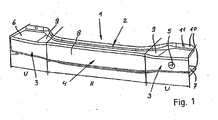
- FIG. 1 shows a bumper assembly 1 for a motor vehicle not shown in detail.
- the bumper assembly 1 is made by forming a board made of a heat-treatable steel and profiled in cross-section U-shaped.
- the bumper assembly 1 comprises two functional components, namely a bumper cross member 2 and integrally formed with the bumper cross member 2 crash boxes, which in this embodiment end-side Form connecting portions 3, for fixing the bumper cross member 2 to longitudinal members of the motor vehicle.
- the area between the attachment sections 3 is referred to as center section 4.
- the U-shaped profiled bumper cross member 2 has with its open side in the direction of the longitudinal members, not shown. Accordingly, its front is closed except for an opening 5 for performing a towing in the right in the image plane connection section 3.
- a in the installation position substantially in the horizontal direction extending upper flange 6 and a lower flange 7 are substantially parallel to each other and are connected to each other via a front web 8.
- the distance between upper flange 6 and lower flange 7 and the width of the web vary over the longitudinal extent of the bumper assembly 1. In particular, the width measured in the vertical direction of the web 8 decreases towards the ends, so that the distance between the upper flange 6 and lower flange 7 in the area The change in the distance is not abrupt, but continuously within transitional sections 9.
- the transition sections 9 are also characterized in that the depth of the U-shaped profiled bumper cross member 2 increases.
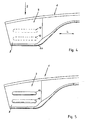
- the width of the upper belt 6 and the lower belt 7 is therefore maximum in the connecting sections 3, which form the crash boxes. This is especially the representations of FIGS. 4 and 5 to recognize. The reason is to be seen in the fact that a sufficient deformation is to be provided in the region of the connecting sections 3, whereas the resulting accumulation of material in the center section 4 is required, so that the width of the upper belt 6 and the lower belt 7 in the middle section 4 are significantly lower can.
- the special thing about the FIG. 1 illustrated bumper assembly is the one-piece nature of the bumper cross member 2 with serving as crash boxes connection sections 3 and the different material properties of the center section 4 and the connection sections 3.
- the area marked H, ie the area of the center section 4 has been cured, whereas with U marked areas, ie the connection sections 3, are uncured. This results in different material properties over the longitudinal course of the bumper assembly 1 with the aim of forming flexurally soft connecting portions 3 of a rigid middle section. 4
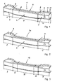
- the embodiment of the FIG. 2 is different from the one of FIG. 1 in that the circuit board from which the bumper arrangement 1 a is manufactured has regions of different wall thicknesses and / or material qualities.
- the starting material used was a tailored welded blank, which was configured such that a steel material A is used in the area of the left attachment section 3 in the image plane, while a steel material B is used in the center section 4 and finally a steel material in the second attachment section 3 C.
- the areas over which the individual materials extend are marked with the letters A, B, C.
- the different materials A, B, C stand for different material grades, but also for different wall thicknesses, so that a tailored bumper arrangement can be produced by the use of tailored welded blanks.
- a bumper assembly 1b is shown consisting of a tailored rolled blank is made.
- the board consists of a single material whose thickness ranges are marked in the present embodiment with I to V. It is conceivable that the wall thickness in the areas I and V is identical. Of course, deviations between all wall thickness ranges and additional heat treatments are possible to produce a crash test requirements sufficient bumper assembly 1b.
- FIG. 4 shows a detail of the bumper assembly 1 in plan view. It is a connection section 3, which is cured with the exception of the dashed line areas 12, 13.
- the areas 12, 13 have either been recessed during the hardening process or deliberately heated in order to reduce the strength again.
- the uncured or heated regions 12, 13 extend transversely to the longitudinal extent L of the bumper assembly 1, so that in the direction of the impact direction indicated by S they effect a specific folding of the attachment portion 3 and thus a desired deformation.
- FIG. 5 is different from the one of FIG. 4 in that likewise in the longitudinal extent L of the bumper cross member 2 successive weakenings in the upper flange 7 are formed. However, these are elongated holes 14, 15, which have the effect of the targeted with respect to the structure-modified areas 12, 13, namely the reduction of the rigidity of the connecting portion 3 to improve the plastic deformability.
Landscapes
- Engineering & Computer Science (AREA)
- Mechanical Engineering (AREA)
- Heat Treatment Of Articles (AREA)
- Body Structure For Vehicles (AREA)
Claims (12)
- Procédé pour la fabrication d'un agencement de pare-chocs (1) d'un véhicule automobile par déformation d'une plaque pour donner une traverse de pare-chocs (2) présentant en section transversale un profil en forme de U qui comporte un tronçon médian (4) et des tronçons de liaison (3), raccordés aux extrémités du tronçon médian (4) et servant de boîtiers déformables dits "crashbox", comprenant les étapes suivantes :a) préparation d'une plaque en acier susceptible d'être traitée ;b) déformation de la plaque pour donner l'agencement de pare-chocs (1);c) durcissement du tronçon médian (4) et des tronçons de liaison (3) pendant l'étape b) ou à la suite de celle-ci, de sorte que, dans une membrure supérieure (6) et/ou dans une membrure inférieure (7), s'étendant sensiblement en direction horizontale, des tronçons de liaison (3), des zones partielles (12, 13)- soit restent non durcies,- soit sont échauffées pour réduire leur solidité.
- Procédé pour la fabrication d'un agencement de pare-chocs (1a) d'un véhicule automobile par déformation d'une plaque pour donner une traverse de pare-chocs (2) présentant en section transversale un profil en forme de U qui comporte un tronçon médian (4) et des tronçons de liaison (3), raccordés aux extrémités du tronçon médian (4) et servant de boîtiers déformables dits "crashbox", comprenant les étapes suivantes :a) préparation de plusieurs plaques en acier susceptibles d'être traitées, avec des épaisseurs différentes et/ou des matériaux de qualités différentes ;b) soudage des plaques pour réaliser un tailored welded blank;c) déformation de la plaque en acier pour donner l'agencement de pare-chocs (1a), de telle manière que l'épaisseur et/ou la qualité du matériau dans le tronçon médian (4) diffère de l'épaisseur et/ou de la qualité du matériau dans les tronçons de liaison (3) ;d) durcissement du tronçon médian (4) et des tronçons de liaison (3) pendant l'étape b) ou à la suite de celle-ci, de sorte que, dans une membrure supérieure (6) et/ou dans une membrure inférieure (7), s'étendant sensiblement en direction horizontale, des tronçons de liaison (3), des zones partielles (12, 13)- soit restent non durcies,- soit sont échauffées pour réduire leur solidité.
- Procédé pour la fabrication d'un agencement de pare-chocs (1b) d'un véhicule automobile par déformation d'une plaque pour donner une traverse de pare-chocs (2) présentant en section transversale un profil en forme de U qui comporte un tronçon médian (4) et des tronçons de liaison (3), raccordés aux extrémités du tronçon médian (4) et servant de boîtiers déformables dits "crashbox", comprenant les étapes suivantes :a) préparation d'une plaque en acier susceptible d'être traitée, à partir d'un tailored rolled blank ;b) déformation de la plaque pour donner l'agencement de pare-chocs (1b), de telle manière que l'épaisseur dans le tronçon médian (4) diffère de l'épaisseur dans les tronçons de liaison (3) ;c) durcissement du tronçon médian (4) et des tronçons de liaison (3) pendant l'étape b) ou à la suite de celle-ci, de sorte que, dans une membrure supérieure (6) et/ou dans une membrure inférieure (7), s'étendant sensiblement en direction horizontale, des tronçons de liaison (3), des zones partielles (12, 13)- soit restent non durcies,- soit sont échauffées pour réduire leur solidité.
- Procédé selon l'une des revendications 1 à 3, caractérisé en ce que plusieurs zones (12, 13) non durcies ou échauffées sont réalisées à la suite les unes des autres transversalement à l'extension longitudinale (c) de l'agencement de pare-chocs (2).
- Procédé selon l'une des revendications 1 à 4, caractérisé en ce qu'au moins deux trous oblongs (14, 15) qui se suivent mutuellement
transversalement à l'extension longitudinale de la traverse de pare-chocs (2) sont ménagés dans la région des tronçons de liaison (3) dans une membrure supérieure (6) et/ou dans une membrure inférieure (7) qui s'étend sensiblement en direction horizontale. - Procédé selon la revendication 5, caractérisé en ce que les trous oblongs (14, 15) sont réalisés avant la déformation de la plaque pour donner une traverse de pare-chocs.
- Agencement de pare-chocs d'un véhicule automobile, comprenant les caractéristiques suivantes :- une plaque en acier susceptible d'être traité qui est déformée pour donner une traverse de pare-chocs (2) présentant en section transversale un profil en forme de U,- la traverse de pare-chocs (2) comporte un tronçon médian (4) et deux tronçons de liaison (3) qui se raccordent aux extrémités au tronçon médian (4),- les tronçons de liaison (3) servent de boîtiers déformables dits "crashbox",- le tronçon médian (4) est durci,- dans une membrure supérieure (6) et/ou dans une membrure inférieure (7), s'étendant sensiblement en direction horizontale, des tronçons de liaison (3), des zones partielles (12, 13) sont réalisées- soit non durcies,- soit avec une solidité réduite par échauffement.
- Agencement de pare-chocs d'un véhicule automobile, comprenant les caractéristiques suivantes :- plusieurs plaques en acier susceptible d'être traité avec des épaisseurs différentes et/ou des matériaux de qualités différentes forment un tailored welded blank qui est déformé pour donner une traverse de pare-chocs (2) présentant en section transversale un profil en forme de U,- la traverse de pare-chocs (2) comporte un tronçon médian (4) et des tronçons de liaison (3) qui se raccordent aux extrémités au tronçon médian (4),- la plaque en acier réalisée sous forme de "tailored welded blank" est configurée de telle manière que l'épaisseur et/ou la qualité du matériau dans le tronçon médian (4) diffère de l'épaisseur et/ou de la qualité du matériau dans les tronçons de liaison (3) ;- les tronçons de liaison (3) servent de boîtiers déformables dits "crashbox",- le tronçon médian (4) est durci,- dans une membrure supérieure (6) et/ou dans une membrure inférieure (7), s'étendant sensiblement en direction horizontale, des tronçons de liaison, des zones partielles (12, 13) sont réalisées- soit non durcies,- soit avec une solidité réduite par échauffement.
- Agencement de pare-chocs d'un véhicule automobile, comprenant les caractéristiques suivantes :- une plaque en acier susceptible d'être traité constituée par un tailored rolled blank qui est déformé pour donner une traverse de pare-chocs (2) présentant en section transversale un profil en forme de U,- la traverse de pare-chocs (2) comporte un tronçon médian (4) et des tronçons de liaison (3) qui se raccordent aux extrémités au tronçon médian (4),- la plaque en acier susceptible d'être traité est configurée de telle manière que l'épaisseur et/ou la qualité du matériau dans le tronçon médian (4) diffère de l'épaisseur et/ou de la qualité du matériau dans les tronçons de liaison (3) ;- les tronçons de liaison (3) servent de boîtiers déformables dits "crashbox",- le tronçon médian (4) est durci,- dans une membrure supérieure (6) et/ou dans une membrure inférieure (7), s'étendant sensiblement en direction horizontale, des tronçons de liaison, des zones partielles (12, 13) sont réalisées- soit non durcies,- soit avec une solidité réduite par échauffement.
- Agencement de pare-chocs selon l'une des revendications 7 à 9, caractérisé en ce que plusieurs zones (12, 13) non durcies ou échauffées sont réalisées à la suite les unes des autres transversalement à l'extension longitudinale (L) de l'agencement de pare-chocs (2).
- Agencement de pare-chocs selon la revendication 10, caractérisé en ce qu'au moins deux trous oblongs (14, 15) qui se suivent mutuellement transversalement à l'extension longitudinale de la traverse de pare-chocs (2) sont ménagés dans la région des tronçons de liaison (3) dans une membrure supérieure (6) et/ou dans une membrure inférieure (7) qui s'étend sensiblement en direction horizontale.
- Agencement de pare-chocs selon la revendication 11, caractérisé en ce que les trous oblongs (14, 15) sont réalisés dans la plaque avant la déformation de la plaque pour donner une traverse de pare-chocs (2).
Applications Claiming Priority (1)
| Application Number | Priority Date | Filing Date | Title |
|---|---|---|---|
| DE102007038496A DE102007038496A1 (de) | 2007-08-14 | 2007-08-14 | Verfahren zur Herstellung einer Stoßfängeranordnung eines Kraftfahrzeugs |
Publications (2)
| Publication Number | Publication Date |
|---|---|
| EP2025560A1 EP2025560A1 (fr) | 2009-02-18 |
| EP2025560B1 true EP2025560B1 (fr) | 2010-08-11 |
Family
ID=39832715
Family Applications (1)
| Application Number | Title | Priority Date | Filing Date |
|---|---|---|---|
| EP08014133A Ceased EP2025560B1 (fr) | 2007-08-14 | 2008-08-07 | Procédé de fabrication d'un agencement de pare-chocs d'un véhicule automobile |
Country Status (3)
| Country | Link |
|---|---|
| US (1) | US20090045638A1 (fr) |
| EP (1) | EP2025560B1 (fr) |
| DE (2) | DE102007063629B4 (fr) |
Families Citing this family (27)
| Publication number | Priority date | Publication date | Assignee | Title |
|---|---|---|---|---|
| DE102009003508B4 (de) * | 2009-02-19 | 2013-01-24 | Thyssenkrupp Steel Europe Ag | Verfahren zur Herstellung eines pressgehärteten Metallbauteils |
| DE102009032651A1 (de) * | 2009-07-09 | 2011-01-13 | Benteler Automobiltechnik Gmbh | Verfahren zur Herstellung einer Karosserie für ein Kraftfahrzeug und Karosserie |
| DE102009043022A1 (de) | 2009-09-28 | 2011-03-31 | Benteler Automobiltechnik Gmbh | Stoßfängerquerträger als Bestandteil eines Stoßfängers eines Kraftfahrzeuges |
| DE102010012831B4 (de) * | 2010-03-25 | 2023-02-16 | Benteler Automobiltechnik Gmbh | Getriebetunnel |
| DE102010012825B4 (de) * | 2010-03-25 | 2012-03-22 | Benteler Automobiltechnik Gmbh | Querträger sowie Stoßträgeranordnung |
| DE102010014999C5 (de) | 2010-04-14 | 2017-12-28 | Benteler Automobiltechnik Gmbh | Kraftfahrzeugstoßfängeranordnung und Stoßfängerbaukastensystem |
| CA2804819A1 (fr) | 2010-08-03 | 2012-02-09 | Cosma Engineering Europe Ag | Ensemble pare-chocs |
| US9302638B2 (en) * | 2010-10-29 | 2016-04-05 | Sabic Global Technologies B.V. | Unitary energy absorbing assembly and method of making the same |
| DE102010050013B4 (de) | 2010-11-02 | 2020-07-09 | Benteler Automobiltechnik Gmbh | Stoßfängeranordnung für ein Kraftfahrzeug |
| DE102010054638A1 (de) | 2010-12-15 | 2012-06-21 | Benteler Automobiltechnik Gmbh | Stoßfänger für ein Kraftfahrzeug |
| DE102012015246A1 (de) * | 2012-06-01 | 2013-12-05 | Westfalia-Automotive Gmbh | Trägeranordnung für eine Anhängekupplung mit einem gehärteten Tragbauteil |
| JP6014417B2 (ja) * | 2012-08-28 | 2016-10-25 | 株式会社アステア | バンパー |
| JP6014430B2 (ja) * | 2012-09-12 | 2016-10-25 | 株式会社アステア | バンパー |
| US20140361558A1 (en) * | 2013-06-10 | 2014-12-11 | Shape Corp. | Variable thickness roll formed beam |
| US8985671B1 (en) | 2013-10-22 | 2015-03-24 | Ford Global Technologies, Llc | V shape bumper extension |
| CN103817192A (zh) * | 2014-01-28 | 2014-05-28 | 无锡红弦汽车轻量化科技有限公司 | 热成形钢板分段强化类零件的压力冷却工艺及模具液压装置 |
| DE102014226542A1 (de) * | 2014-12-19 | 2016-06-23 | Bayerische Motoren Werke Aktiengesellschaft | Pressgehärtetes Blechbauteil mit wenigstens einer Sollbruchstelle, sowie Bauteilverbund und Kraftfahrzeugkarosserie mit solchem Blechbauteil |
| DE102015203644A1 (de) | 2015-03-02 | 2016-09-08 | Bayerische Motoren Werke Aktiengesellschaft | Pressgehärtetes Blechformteil mit unterschiedlichen Blechdicken und Festigkeiten |
| FR3037019A1 (fr) | 2015-06-03 | 2016-12-09 | Peugeot Citroen Automobiles Sa | Dispositif d’absorption de chocs pour structure avant ou arriere d’un vehicule et vehicule equipe d’un tel dispositif. |
| DE102015114105B4 (de) | 2015-08-25 | 2018-11-29 | Benteler Automobiltechnik Gmbh | Aufprallträger für ein Kraftfahrzeug sowie Verfahren zu seiner Herstellung |
| SE541585C2 (en) * | 2016-11-22 | 2019-11-12 | Gestamp Hardtech Ab | Bumper beam |
| US10556624B2 (en) | 2017-06-16 | 2020-02-11 | Ford Global Technologies, Llc | Vehicle underbody component protection assembly |
| US11141769B2 (en) | 2017-06-16 | 2021-10-12 | Ford Global Technologies, Llc | Method and apparatus for forming varied strength zones of a vehicle component |
| US10633037B2 (en) | 2017-06-16 | 2020-04-28 | Ford Global Technologies, Llc | Vehicle underbody assembly with thermally treated rear rail |
| US10399519B2 (en) | 2017-06-16 | 2019-09-03 | Ford Global Technologies, Llc | Vehicle bumper beam with varied strength zones |
| DE102019108907B4 (de) * | 2019-04-04 | 2021-06-02 | Benteler Automobiltechnik Gmbh | Stoßfängeranordnung mit verclinchter Aufnahme |
| FR3126935B1 (fr) * | 2021-09-14 | 2025-09-26 | Psa Automobiles Sa | Traverse de pare-chocs présentant des affaiblissements autour d’une douille d’arrimage. |
Family Cites Families (7)
| Publication number | Priority date | Publication date | Assignee | Title |
|---|---|---|---|---|
| US4010969A (en) * | 1973-05-17 | 1977-03-08 | Houdaille Industries, Inc. | Impact resistant lightweight, low cost automobile bumpers and method of making same |
| DE19849358C2 (de) * | 1998-10-27 | 2000-10-12 | Benteler Werke Ag | Stoßfänger für Kraftfahrzeuge |
| NO990503D0 (no) | 1999-02-03 | 1999-02-03 | Norsk Hydro As | St°tfanger og fremgangsmÕte ved fremstilling av samme |
| JP2001180398A (ja) * | 1999-12-24 | 2001-07-03 | Futaba Industrial Co Ltd | テーラードブランクからなるバンパーリィンホース |
| SE0501173L (sv) | 2005-05-25 | 2006-04-04 | Gestamp Hardtech Ab | Stötfångarbalk |
| SE528353C2 (sv) * | 2005-12-15 | 2006-10-24 | Gestamp Hardtech Ab | Bågformad stötfångarbalk för fordon |
| EP1854675B1 (fr) * | 2006-05-11 | 2011-08-03 | Wagon Automotive GmbH | Poutre de pare-chocs de véhicule automobile |
-
2007
- 2007-08-14 DE DE102007063629.8A patent/DE102007063629B4/de not_active Expired - Fee Related
-
2008
- 2008-08-07 DE DE502008001110T patent/DE502008001110D1/de active Active
- 2008-08-07 EP EP08014133A patent/EP2025560B1/fr not_active Ceased
- 2008-08-14 US US12/191,636 patent/US20090045638A1/en not_active Abandoned
Also Published As
| Publication number | Publication date |
|---|---|
| DE102007063629A1 (de) | 2009-02-26 |
| EP2025560A1 (fr) | 2009-02-18 |
| US20090045638A1 (en) | 2009-02-19 |
| DE502008001110D1 (de) | 2010-09-23 |
| DE102007063629B4 (de) | 2016-07-07 |
Similar Documents
| Publication | Publication Date | Title |
|---|---|---|
| EP2025560B1 (fr) | Procédé de fabrication d'un agencement de pare-chocs d'un véhicule automobile | |
| DE102010014999C5 (de) | Kraftfahrzeugstoßfängeranordnung und Stoßfängerbaukastensystem | |
| DE69807988T2 (de) | Verstärkungselement für Kfz-Hohlprofile, mit verminderter Wanddicke am Endabschnitt | |
| DE102017124590B4 (de) | Einstückiger Doppelquerträger aus Extrusionsprofil | |
| DE102013100720B4 (de) | Querträger für ein Kraftfahrzeug | |
| EP3901006B1 (fr) | Pièce structurale de véhicule automobile | |
| WO2012007346A1 (fr) | Renfort de pied milieu d'un véhicule automobile | |
| DE102007038036B4 (de) | Verfahren zur Herstellung eines rohrförmigen Tragprofils für einen Instrumententräger | |
| DE102007038496A1 (de) | Verfahren zur Herstellung einer Stoßfängeranordnung eines Kraftfahrzeugs | |
| EP4477477A2 (fr) | Agencement de pare-chocs pour un véhicule automobile | |
| DE202021103263U1 (de) | Stoßfängeranordnung mit zusätzlicher Abstützung | |
| DE102020104097B4 (de) | Kraftfahrzeug-Stoßfänger | |
| DE102021128850B4 (de) | Stoßfängerquerträger mit lokaler Deformationszone | |
| DE202021103264U1 (de) | Stoßfängeranordnung für ein Kraftfahrzeug | |
| DE202009002575U1 (de) | Profilteil als Karosseriekomponente eines Kraftfahrzeuges | |
| DE102013107179B4 (de) | Stoßabsorptionsvorrichtung für ein Kraftfahrzeug | |
| DE102018109992B4 (de) | Kraftfahrzeug-Stoßfängeranordnung und Verfahren zur Herstellung | |
| WO2024038194A1 (fr) | Support de tableau de bord | |
| DE102018107846B4 (de) | Verfahren zum Herstellen eines Profilbauteils sowie Fahrzeugquerträger oder Fahrzeuglängsträger | |
| DE102020109579A1 (de) | Träger für ein Kraftfahrzeug und Verfahren zur Herstellung eines Trägers | |
| DE10043880A1 (de) | Stossfänger | |
| DE102023122062B4 (de) | Scheiben- und/oder Dachrahmen für ein Kraftfahrzeug | |
| WO2003041978A1 (fr) | Flan, piece de carrosserie et procede de production d'une telle piece de carrosserie | |
| DE102023123215A1 (de) | Stoßfängeranordnung für ein Kraftfahrzeug | |
| WO2026017773A1 (fr) | Ensemble pare-chocs pour vehicule motorisé |
Legal Events
| Date | Code | Title | Description |
|---|---|---|---|
| PUAI | Public reference made under article 153(3) epc to a published international application that has entered the european phase |
Free format text: ORIGINAL CODE: 0009012 |
|
| AK | Designated contracting states |
Kind code of ref document: A1 Designated state(s): AT BE BG CH CY CZ DE DK EE ES FI FR GB GR HR HU IE IS IT LI LT LU LV MC MT NL NO PL PT RO SE SI SK TR |
|
| AX | Request for extension of the european patent |
Extension state: AL BA MK RS |
|
| 17P | Request for examination filed |
Effective date: 20090404 |
|
| 17Q | First examination report despatched |
Effective date: 20090702 |
|
| AKX | Designation fees paid |
Designated state(s): DE FR IT |
|
| GRAP | Despatch of communication of intention to grant a patent |
Free format text: ORIGINAL CODE: EPIDOSNIGR1 |
|
| GRAS | Grant fee paid |
Free format text: ORIGINAL CODE: EPIDOSNIGR3 |
|
| RAP1 | Party data changed (applicant data changed or rights of an application transferred) |
Owner name: BENTELER AUTOMOBILTECHNIK GMBH |
|
| GRAA | (expected) grant |
Free format text: ORIGINAL CODE: 0009210 |
|
| AK | Designated contracting states |
Kind code of ref document: B1 Designated state(s): DE FR IT |
|
| REF | Corresponds to: |
Ref document number: 502008001110 Country of ref document: DE Date of ref document: 20100923 Kind code of ref document: P |
|
| PLBE | No opposition filed within time limit |
Free format text: ORIGINAL CODE: 0009261 |
|
| STAA | Information on the status of an ep patent application or granted ep patent |
Free format text: STATUS: NO OPPOSITION FILED WITHIN TIME LIMIT |
|
| 26N | No opposition filed |
Effective date: 20110512 |
|
| REG | Reference to a national code |
Ref country code: DE Ref legal event code: R097 Ref document number: 502008001110 Country of ref document: DE Effective date: 20110512 |
|
| REG | Reference to a national code |
Ref country code: FR Ref legal event code: PLFP Year of fee payment: 8 |
|
| REG | Reference to a national code |
Ref country code: FR Ref legal event code: PLFP Year of fee payment: 9 |
|
| REG | Reference to a national code |
Ref country code: FR Ref legal event code: PLFP Year of fee payment: 10 |
|
| PGFP | Annual fee paid to national office [announced via postgrant information from national office to epo] |
Ref country code: IT Payment date: 20170828 Year of fee payment: 10 Ref country code: FR Payment date: 20170822 Year of fee payment: 10 Ref country code: DE Payment date: 20170829 Year of fee payment: 10 |
|
| REG | Reference to a national code |
Ref country code: DE Ref legal event code: R119 Ref document number: 502008001110 Country of ref document: DE |
|
| PG25 | Lapsed in a contracting state [announced via postgrant information from national office to epo] |
Ref country code: IT Free format text: LAPSE BECAUSE OF NON-PAYMENT OF DUE FEES Effective date: 20180807 Ref country code: DE Free format text: LAPSE BECAUSE OF NON-PAYMENT OF DUE FEES Effective date: 20190301 |
|
| PG25 | Lapsed in a contracting state [announced via postgrant information from national office to epo] |
Ref country code: FR Free format text: LAPSE BECAUSE OF NON-PAYMENT OF DUE FEES Effective date: 20180831 |