EP2025621B1 - Conteneur de mélange et procédé de remplissage - Google Patents
Conteneur de mélange et procédé de remplissage Download PDFInfo
- Publication number
- EP2025621B1 EP2025621B1 EP08161164A EP08161164A EP2025621B1 EP 2025621 B1 EP2025621 B1 EP 2025621B1 EP 08161164 A EP08161164 A EP 08161164A EP 08161164 A EP08161164 A EP 08161164A EP 2025621 B1 EP2025621 B1 EP 2025621B1
- Authority
- EP
- European Patent Office
- Prior art keywords
- vessel
- open mouth
- inner vessel
- outer vessel
- closure
- Prior art date
- Legal status (The legal status is an assumption and is not a legal conclusion. Google has not performed a legal analysis and makes no representation as to the accuracy of the status listed.)
- Ceased
Links
Images


Classifications
-
- B—PERFORMING OPERATIONS; TRANSPORTING
- B65—CONVEYING; PACKING; STORING; HANDLING THIN OR FILAMENTARY MATERIAL
- B65D—CONTAINERS FOR STORAGE OR TRANSPORT OF ARTICLES OR MATERIALS, e.g. BAGS, BARRELS, BOTTLES, BOXES, CANS, CARTONS, CRATES, DRUMS, JARS, TANKS, HOPPERS, FORWARDING CONTAINERS; ACCESSORIES, CLOSURES, OR FITTINGS THEREFOR; PACKAGING ELEMENTS; PACKAGES
- B65D81/00—Containers, packaging elements, or packages, for contents presenting particular transport or storage problems, or adapted to be used for non-packaging purposes after removal of contents
- B65D81/32—Containers, packaging elements, or packages, for contents presenting particular transport or storage problems, or adapted to be used for non-packaging purposes after removal of contents for packaging two or more different materials which must be maintained separate prior to use in admixture
- B65D81/3216—Rigid containers disposed one within the other
- B65D81/3222—Rigid containers disposed one within the other with additional means facilitating admixture
Definitions
- the field of the present invention is multi-compartment mixing containers.
- Containers are known for separately storing two liquids and automatically mixing the two liquids when the container is opened. Reference is made to one such example in U.S. Patent No. 3,856,138 . Such containers have utility when the combination of liquids will react or allow a deterioration of the combination.
- Dual mixing containers which automatically mix liquids upon opening tend to be of complicated design. However, where beverages and other price sensitive products are to be mixed, inexpensive and uncomplicated mechanisms are needed to facilitate use, filling operations, sanitation, possible storage and competitiveness of packaging.
- the present invention is directed to a mixing container employing an outer vessel and an inner vessel and a method for filling such a container.
- the vessels each have an end, an open mouth and a peripheral sidewall therebetween.
- An internal seal is defined by the bottom end of the outer vessel and the open mouth of the inner vessel when brought together.
- a closure is positionable to close the open mouth of the outer vessel.
- the invention provides for automatic mixing of liquids contained in the two vessels when the closure is removed.
- the method of filling provides for an inner vessel with one end closed.
- the mixing container employs a socket which is resiliently mounted in the closure.
- the end of the inner vessel is mountable in the socket which, when assembled with the outer vessel, causes the inner vessel to be resiliently biased against the bottom of the outer vessel to define the interior seal.
- the end of the inner vessel is a closed end. This feature allows the inner vessel to be filled independently without complicated mechanisms, sanitary complexity or extraordinary method steps.
- a method of filling mixing containers includes filling the inner vessel separately and placing the outer vessel over the filled inner vessel with at least partial immersion of the outer vessel to then draw liquid into the outer vessel.
- the closure may then be fully assembled with the outer vessel.
- the method may further include compressing the socket during closure.
- Figure 1 illustrates a mixing container, generally designated 10.
- the mixing container 10 includes an outer vessel 12 with a peripheral sidewall 14 which is conveniently cylindrical but may take on other shapes and configurations.
- a bottom 16 is at one end of the peripheral sidewall 14 and includes a raised surface 18 centrally mounted on the interior surface of the bottom 16 and having a circular periphery thereabout.
- An open mouth 20 is located at the other end of the peripheral sidewall 14 from the bottom 16.
- the open mouth 20 includes interior threads 22. Regardless of the configuration of the peripheral sidewall 14, if interior threads 22 are employed, the open mouth 20 is appropriately cylindrical. If a cork mechanism is employed as a closure, the interior threads 22 would not be employed.
- An inner vessel 24 is illustrated to be in the form of a vial which is conveniently circular in lateral cross section. Again, other shapes may be appropriately employed for aesthetic considerations.
- the inner vessel 24 includes a closed end 26, an open mouth 28 and a peripheral sidewall 30 therebetween.
- a circular resilient seal 32 may be employed about the open mouth 28 of the inner vessel 24.
- the open mouth 28 with the circular resilient seal 32 is sized to fit about the raised surface 18 to effect an interior seal when the inner vessel 24 is assembled with the outer vessel 12.
- the fit between the raised surface 18 and the open mouth 28 of the inner vessel 24 may be enhanced with a more extreme rise to the surface 18 than shown where found necessary.
- the inner vessel 24 may be configured to establish a volumetric ratio to fit any given dual liquid product, such as through variation in the relative diameter of the inner vessel 24 relative to the outer vessel 12.
- the open mouth 20 of the outer vessel 12 should be large enough to accommodate passage of the inner vessel 24 therethrough.
- a closure 34 is positionable to close the open mouth 20 of the outer vessel 12.
- the closure 34 has a cap 36 with a depending cylindrical body 38 having external threads to mate with the interior threads 22 of the outer vessel 12.
- the closure 34 is positionable to develop a conventional seal with the outer vessel 12 but is not called upon to seal the inner vessel 24. Both the outer vessel 12 and the inner vessel 24 are accessible only through the single open mouths 20, 28 of each.
- a socket 40 is mounted within the interior of the closure 34, including a cylindrical flange 42 fitting within the cylindrical body 38 such that some force is required to extract the socket 40 from the closure 34 to assure retention of the inner vessel 24 for operation as described below.
- a bead and groove mechanism may increase the force required for extraction of the socket 40 from the closure 34 if necessary.
- the socket 40 includes a circular dished plate spring 44 about which the cylindrical flange 42 extends. This plate spring 44 is positioned within the closure 34 such that the resilience of the spring is directed away from the cap 36.
- the socket 40 further includes a cavity 46 centrally located on the plate spring 44 to receive the closed end 26 of the inner vessel 24. The cavity 46 is intended to receive the closed end 26 and retain the inner vessel 24 through a mechanism such as adhesive, interference fit (if the socket extends down to the peripheral sidewall 30 of the inner vessel 24) or suction.
- the mixing container 10 is assembled with two different liquids 48, 50.
- One liquid 48 is contained within the inner vessel 24 while the other is contained within the outer vessel 12 in the annular space about the inner vessel 24. This arrangement is illustrated in Figure 2 .
- the liquids 48, 50 best advantaged by the separation available with this container are those which will react with one another or allow deterioration when in combination.
- One example would be the preservative effect of alcohol in sufficient concentrations.
- a flavorful drink that is used at an alcohol concentration below that required to preserve the flavor one of the two liquids might be the diluting water while the other might be the flavored drink with a higher alcohol content.
- the liquid with high alcohol content contains oil
- reducing the alcohol content with water through the mixing process can allow the oil to come out of solution and turn the mixture of the two liquids 48, 50 opaque.
- the choice of which liquid goes in which vessel may be based on preference, relative volumetric need where the sizes of the two vessels 12, 24 are already configured, relative opacity or the physical needs of the liquids.
- the outer fluid would appropriately be transparent or at least sufficiently translucent for the inner vessel to be seen.
- light shielding in the inner vessel 24 to accommodate that sensitivity with the sensitive liquid being in the inner vessel still allows viewing of the inner vessel 24 through a transparent or translucent outer vessel 12.
- the closure 34 has been separated from the outer vessel 12 by unscrewing it therefrom.
- the closure 34 with the inner vessel 24 attached, is then lifted from the outer vessel 12.
- the liquid 48 primarily remains within the inner vessel 24 until the mouth 28 of the inner vessel 24 breaks the surface of the liquid 50.
- some mixing occurs as the inner vessel 24 is withdrawn from the outer vessel 12. The amount of mixing depends to a certain extent on the size of the open mouth 28 of the vessel 24. Where the mixing before the open mouth 28 breaks the surface of the liquid 50 is greater than desired, a smaller mouth 28 can be employed regardless of the main diameter of the inner vessel.
- the inner vessel 24 is filled with liquid to an appropriate height with the inner vessel 24 oriented such that the open mouth 28 faces upwardly.
- the inner vessel 24 is filled with the liquid 48 in that orientation. This step may occur just prior to association with the outer vessel 12 or may be accomplished in an assembly context where multiple such inner vessels 24 are filled and possibly even sealed pending assembly as part of the overall mixing container 10.
- the inner vessel 24 is associated, either before or after being filled with the liquid 48, with the socket 40 and with the closure 34.
- the step of filling and the step of associating the inner vessel 24 with the closure 34 need not occur in seriatim.
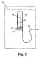
- the outer vessel 12 With the mouth 28 not closed by any temporary seal, the outer vessel 12 is placed over the inner vessel 24 while the inner vessel 24 remains in an orientation with the open mouth 28 facing upwardly.
- the closure is positioned such that it does not fully close the open mouth 20 of the outer vessel 12. This orientation is illustrated in Figure 6 .
- a vacuum tube 52 is introduced into the outer vessel 12 either before or after the outer vessel 12 is placed over the inner vessel 24.
- This vacuum tube 52 is extended upwardly to above the intended level of fill of the outer tube 12 with the liquid 50.
- the open mouth 20 of the outer vessel 12 is immersed in the liquid 50 and vacuum is induced through the vacuum tube 52.
- the entire assembly may be submerged in the liquid 50. However, it is only needed that the outer vessel 12 be immersed into the liquid 50 to the point that the open mouth 20 be covered by the liquid 50.
- the liquid 50 is then drawn into the outer vessel 12 to a level desired by evacuating at least some of the air or other gas within the outer vessel 12. To avoid any mixing of the liquids 48 and 50, the level of fill of the liquid 50 should be below the open mouth 28 of the inner vessel 24. Once the outer vessel 12 is filled, the vacuum tube 52 may be withdrawn from the container.
- the closure 34 is threaded into the open mouth 20 of the outer vessel 12 to close the outer vessel 12.
- the inner vessel 24 is of an appropriate length such that the open mouth 28 of the inner vessel 24 will contact the bottom 16 of the outer vessel 12 as the closure 34 is being installed.
- the dished plate spring 44 is compressed to resiliently bias the open mouth 28 of the inner vessel 24 against the bottom 16 about the raised surface 18 to effect an interior seal.
- the employment of the dished plate spring accommodates variation in manufacturing tolerances, thermal expansion and the like.
- the closed end 26 of the inner vessel 24 allows preloading and easy mating with the closure 34. Once the mixing container is charged, the simple interior seal may then be employed to separate the liquids until automatic mixing for use.
- the filling process disclosed also facilitates the employment of the uncomplicated design.
Landscapes
- Engineering & Computer Science (AREA)
- Mechanical Engineering (AREA)
- Package Specialized In Special Use (AREA)
Claims (7)
- Conteneur de mélange comprenant un récipient externe (12) ayant un fond (16), une bouche ouverte (20) et une paroi latérale périphérique (14) entre la bouche ouverte (20) et le fond (16); un récipient interne (24) ayant une extrémité (26), une bouche ouverte (28) et une paroi latérale périphérique (30) entre l'extrémité (26) et la bouche ouverte (28) ; un joint étanche intérieur défini par le fond du récipient externe (12) et la bouche ouverte (28) du récipient interne (24), la bouche ouverte (28) du récipient interne (24) étant contre le fond (16) du récipient externe (12) ; une fermeture (34) positionnable pour fermer la bouche ouverte (20) du récipient externe (12) ; caractérisé par une douille (40) montée dans la fermeture (34), l'extrémité (26) du récipient interne (24) pouvant être montée dans la douille (40), la bouche ouverte (28) du récipient interne (24) étant pressée de manière élastique contre le fond (16) du récipient externe (12) définissant le joint étanche intérieur.
- Conteneur de mélange selon la revendication 1, dans lequel le joint intérieur comprend un joint étanche élastique (32) sur la bouche ouverte circulaire (28) du récipient interne (24).
- Conteneur de mélange selon la revendication 1, dans lequel la douille (40) comprend un ressort circulaire à lames en tôle emboutie (44) retenue dans la fermeture (34) et une cavité (46) située au centre du ressort circulaire à lames en tôle emboutie (44) et reçoit l'extrémité du récipient interne (24).
- Conteneur de mélange selon la revendication 1, dans lequel la fermeture (34) ne peut être positionnée que pour fermer la bouche ouverte (20) du récipient externe (12), l'extrémité (26) du récipient interne (24) est une extrémité fermée (26) avec un accès au récipient interne (24) uniquement à travers la bouche ouverte (28) du récipient interne (24) et le fond (16) du récipient externe (12) étant un fond fermé (16) avec un accès au récipient externe (12) uniquement à travers la bouche ouverte (20) du récipient externe (12).
- Conteneur de mélange selon la revendication 1, dans lequel le récipient externe (12) est transparent et le récipient interne (24) a une protection contre la lumière.
- Conteneur de mélange selon la revendication 1, comprenant en outreun premier liquide (48) dans le récipient interne (24) ;un second liquide (50) dans le récipient externe (12), le second liquide (50) étant transparent ou au moins suffisamment translucide pour pouvoir observer le récipient interne (24), un mélange du premier liquide (48) et du second liquide (50) étant opaque.
- Procédé pour remplir un conteneur de mélange (10) avec deux liquides (48-50), le conteneur de mélange (10) comprenant un récipient externe (12) ayant un fond (16), une bouche ouverte (20) et une paroi latérale périphérique (14) entre la bouche ouverte (20) et le fond (16) ; un récipient interne (24) ayant une extrémité (26), une bouche ouverte (28) et une paroi latérale périphérique (30) entre l'extrémité (26) et la bouche ouverte (28) ; un joint étanche intérieur défini par le fond (16) du récipient externe (12) et la bouche ouverte (28) du récipient interne (24), la bouche ouverte (28) du récipient interne (24) étant contre le fond (16) du récipient externe (12) ; une fermeture (34) positionnable pour fermer la bouche ouverte (20) du récipient externe (12) ; et une douille (40) montée dans la fermeture (34), l'extrémité (26) du récipient interne (24) pouvant être montée dans la douille (40) avec la bouche ouverte (28) du récipient interne (24) pressée de manière élastique contre le fond (16) du récipient externe (12) définissant le joint étanche intérieur; le procédé comprenant le remplissage du récipient interne (24) avec un premier (48) des deux liquides (48-50) ; le placement du récipient externe (12) par-dessus le récipient interne rempli (24) avec la fermeture (34) assemblée avec le récipient interne (24) et ne fermant pas complètement la bouche (20) du récipient externe (12) ; l'immersion des récipients interne et externe (24, 12) avec la fermeture (34) ne fermant pas complètement la bouche (20) du récipient externe (12) dans un second (50) des deux liquides (48-50) au moins pour recouvrir la bouche (20) du récipient externe (12) ; au moins l'évacuation partielle du récipient externe (12) avec la fermeture (34) ne fermant pas complètement la bouche (20) du récipient externe (12) tandis que les récipients interne et externe (24, 12) immergés au moins pour recouvrir la bouche (20) du récipient externe (12) ; la fermeture de la bouche (20) du récipient externe (12) avec la fermeture comprenant la compression de la douille (40) contre la sollicitation élastique.
Applications Claiming Priority (1)
| Application Number | Priority Date | Filing Date | Title |
|---|---|---|---|
| US11/836,699 US8104611B2 (en) | 2007-08-09 | 2007-08-09 | Mixing container and method of filling |
Publications (2)
| Publication Number | Publication Date |
|---|---|
| EP2025621A1 EP2025621A1 (fr) | 2009-02-18 |
| EP2025621B1 true EP2025621B1 (fr) | 2010-04-28 |
Family
ID=39961943
Family Applications (1)
| Application Number | Title | Priority Date | Filing Date |
|---|---|---|---|
| EP08161164A Ceased EP2025621B1 (fr) | 2007-08-09 | 2008-07-25 | Conteneur de mélange et procédé de remplissage |
Country Status (3)
| Country | Link |
|---|---|
| US (1) | US8104611B2 (fr) |
| EP (1) | EP2025621B1 (fr) |
| DE (1) | DE602008001087D1 (fr) |
Families Citing this family (19)
| Publication number | Priority date | Publication date | Assignee | Title |
|---|---|---|---|---|
| US8875874B2 (en) * | 2007-08-09 | 2014-11-04 | Biosphere Spirits, Llc | Multi-compartment mixing container and method of filling |
| US20090114773A1 (en) * | 2007-11-05 | 2009-05-07 | Helou Jr Elie | Methods for fuel-efficient transportation of cargo by aircraft |
| US20090211927A1 (en) * | 2008-02-21 | 2009-08-27 | Wu Kuo Cheng | Container structure for contain different beverages |
| US20090294397A1 (en) * | 2008-05-27 | 2009-12-03 | Wu Kuo Cheng | Container for contain different beverages |
| JP4696186B2 (ja) * | 2008-06-10 | 2011-06-08 | 容子 中鼻 | 試料収納体 |
| JP5467822B2 (ja) * | 2009-09-07 | 2014-04-09 | 株式会社トクヤマデンタル | 液混合容器 |
| WO2011049534A2 (fr) * | 2009-10-20 | 2011-04-28 | Romchat Sangkavatana | Récipient contenant des liquides séparés |
| US20130026124A1 (en) * | 2011-07-27 | 2013-01-31 | Wu Kuo Cheng | Container Capable of Accommodating Multiple Substances |
| FR2978957A1 (fr) * | 2011-08-12 | 2013-02-15 | Leonore Esther Bacot | Contenant alimentaire permettant deux modes de cuisson simultanes |
| FR2982249B1 (fr) * | 2011-11-07 | 2014-12-26 | Michel Camilleri | Godet jetable pour un produit bi-composant a monter sur un outil de pulverisation |
| USD715343S1 (en) * | 2013-01-10 | 2014-10-14 | Nitto Denko Corporation | Container for mixer |
| USD715346S1 (en) * | 2013-01-10 | 2014-10-14 | Nitto Denko Corporation | Container for mixer |
| USD715345S1 (en) * | 2013-01-10 | 2014-10-14 | Nitto Denko Corporation | Container for mixer |
| USD715344S1 (en) * | 2013-01-10 | 2014-10-14 | Nitto Denko Corporation | Container for mixer |
| JP6167184B2 (ja) * | 2013-01-14 | 2017-07-19 | ミシェル カミレーリ | 調製及び塗装または、少なくとも2つの成分を混合したものに由来する生成物をスプレーするための、スプレーツールのカップとして用いられる使い捨てアセンブリ |
| CN106103305A (zh) * | 2014-03-13 | 2016-11-09 | 普尼娜·阿龙 | 用于储存及混合材料的容器装置 |
| US9114910B1 (en) * | 2014-04-29 | 2015-08-25 | Joel Schommer | Mixing container |
| US20180072481A1 (en) * | 2016-09-12 | 2018-03-15 | Barry Boatner | Multi-Chambered Beverage Container and Mixing Apparatus |
| JP7323460B2 (ja) * | 2017-06-21 | 2023-08-08 | ソシエテ・デ・プロデュイ・ネスレ・エス・アー | 液体供給装置 |
Family Cites Families (42)
| Publication number | Priority date | Publication date | Assignee | Title |
|---|---|---|---|---|
| US933444A (en) | 1909-05-19 | 1909-09-07 | Robert Henke Jr | Paint-can. |
| US1706335A (en) | 1927-06-03 | 1929-03-19 | Standard Varnish Works | Receptacle for paints, etc. |
| US2661870A (en) | 1948-09-28 | 1953-12-08 | Alfred G Huenergardt | Multiple liquid dispensing container |
| US2661871A (en) | 1950-04-17 | 1953-12-08 | Alfred G Huenergardt | Multiple liquid dispensing container |
| US2884149A (en) * | 1956-02-18 | 1959-04-28 | Zimmermann Ehrenfried | Closures for bottles and like containers |
| US3076573A (en) | 1960-05-12 | 1963-02-05 | Bristol Myers Co | Dispensing closure |
| CH399301A (de) * | 1962-07-02 | 1965-09-15 | Ver Aluminiumfabriken Ristau | Gefässverschluss mit federndem Abstandhalter |
| US3275180A (en) * | 1965-01-04 | 1966-09-27 | Lermer Packaging Corp | Mailing container construction |
| US3459295A (en) | 1967-12-04 | 1969-08-05 | Dow Chemical Co | Multiple compartmented container |
| US3705661A (en) | 1970-02-20 | 1972-12-12 | Peter J Davis | Multiple compartment thermally insulated container |
| US3696919A (en) | 1970-10-08 | 1972-10-10 | Colgate Palmolive Co | Double container with mixing means |
| FR2128357B3 (fr) * | 1971-03-12 | 1974-05-10 | Harre & Co A | |
| US3743520A (en) | 1971-09-03 | 1973-07-03 | J Croner | Compartmented beverage container |
| US3856138A (en) | 1973-05-31 | 1974-12-24 | Shionogi & Co | Compartmentalized container |
| US4215786A (en) * | 1978-11-01 | 1980-08-05 | Vertes Michael A | Container cap having means to protect articles |
| AT368463B (de) | 1978-12-21 | 1982-10-11 | Aigner Weinkellerei | Flasche mit getrennten abteilungen |
| DE3109921A1 (de) | 1981-03-14 | 1982-09-23 | Wella Ag, 6100 Darmstadt | Zwei-komponenten-verpackung fuer schuettbare medien |
| US4410085A (en) | 1982-05-03 | 1983-10-18 | Manufacture Lyonnaise De Bouchage | Drinking goblet enabling two doses of constituents to be mixed just before consumption |
| US4585150A (en) | 1983-09-07 | 1986-04-29 | The Clorox Company | Multiple liquid proportional dispensing device |
| CH667437A5 (it) | 1985-12-06 | 1988-10-14 | Intecser Sa | Dispositivo atto a mantenere separate in un contenitore, sino al momento dell'uso e poi a miscelarle immediatamente prima di erogarle, due diverse sostanze, in particolare resine a due componenti. |
| US4765514A (en) | 1987-01-08 | 1988-08-23 | Berglund Albert I | Container |
| FR2612161B1 (fr) * | 1987-03-13 | 1989-06-23 | Air Sec Sa | Tube de conditionnement de comprimes, cachets ou articles similaires, avec boite de reserve |
| GB8726062D0 (en) | 1987-11-06 | 1987-12-09 | Plaspharm Uk Ltd | Fluid dispensing devices |
| US4762224A (en) | 1987-12-21 | 1988-08-09 | Hall John E | Mixing container with segregated ingredient compartments |
| DE3837595A1 (de) | 1988-04-14 | 1990-05-10 | Goldwell Gmbh | Doppelkammer-behaelter |
| DE3816859A1 (de) | 1988-05-18 | 1989-11-23 | Henkel Kgaa | Mehrkomponentenbehaeltnis |
| US4915255A (en) * | 1988-09-22 | 1990-04-10 | Cytosciences, Inc. | Transportable specimen container including removable centrifuge tube |
| IL95985A0 (en) | 1990-10-15 | 1991-07-18 | Shlomo Lev | Multi-compartment liquid storage container |
| US5114411A (en) * | 1990-11-19 | 1992-05-19 | Habley Medical Technology Corporation | Multi-chamber vial |
| US5352196A (en) * | 1990-11-19 | 1994-10-04 | Habley Medical Technology Corporation | Mixing vial |
| US5160791A (en) * | 1990-12-12 | 1992-11-03 | E. I. Du Pont De Nemours And Company | Non-stick coating system with two perfluorocarbon resins in topcoat for concentration gradient |
| US5316146A (en) * | 1991-03-06 | 1994-05-31 | Ulster Scientific, Inc. | Vial transporter |
| US5356040A (en) | 1992-03-31 | 1994-10-18 | Maplast S.R.L. | Container particulary for multicomponent products |
| US5447226A (en) | 1992-06-09 | 1995-09-05 | Societe De Conseils Et D'eutdes Des Emballages (S.C.E.E.) | Dual compartment container with means for mixing and dispensing a product |
| US5217145A (en) | 1992-08-28 | 1993-06-08 | Glaxo Inc. | Multiple product dispenser |
| US5398827A (en) | 1993-08-20 | 1995-03-21 | Flair Communications Agency, Inc. | Multi-vesselled beverage container |
| EP0779050A1 (fr) * | 1995-12-11 | 1997-06-18 | Edward Jonathan Hoffman | Tasse avec figure |
| US6398051B1 (en) * | 2000-07-19 | 2002-06-04 | Owens-Illinois Closure Inc. | Tablet package including a tablet hold-down device |
| US6464078B1 (en) * | 2000-08-08 | 2002-10-15 | Reid A. Grossnickle | Article container with multipurpose outer chamber |
| US7243787B2 (en) * | 2003-03-26 | 2007-07-17 | Nipro Corporation | Medicine bag |
| US7270233B2 (en) * | 2005-07-21 | 2007-09-18 | Kindt John H | Package for separate compounds to be mixed |
| US20090211927A1 (en) * | 2008-02-21 | 2009-08-27 | Wu Kuo Cheng | Container structure for contain different beverages |
-
2007
- 2007-08-09 US US11/836,699 patent/US8104611B2/en not_active Expired - Fee Related
-
2008
- 2008-07-25 DE DE602008001087T patent/DE602008001087D1/de active Active
- 2008-07-25 EP EP08161164A patent/EP2025621B1/fr not_active Ceased
Also Published As
| Publication number | Publication date |
|---|---|
| EP2025621A1 (fr) | 2009-02-18 |
| DE602008001087D1 (de) | 2010-06-10 |
| US20100018880A1 (en) | 2010-01-28 |
| US8104611B2 (en) | 2012-01-31 |
Similar Documents
| Publication | Publication Date | Title |
|---|---|---|
| US8104611B2 (en) | Mixing container and method of filling | |
| JP4217448B2 (ja) | ボトルキャップ | |
| JP4340313B2 (ja) | ボトルキャップ | |
| US9114910B1 (en) | Mixing container | |
| CN111703728B (zh) | 一种下压式即配型容器用瓶盖和容器 | |
| CA2854401C (fr) | Bouteille comprenant une fermeture amovible creuse | |
| JP3139281U (ja) | ボトルキャップ | |
| KR20240015761A (ko) | 음료 즉석 혼합을 위한 뚜껑 구조체 | |
| CN213769842U (zh) | 一种固液隔离即开即溶饮品包装瓶 | |
| CN213057865U (zh) | 一种按压式双物料合装瓶 | |
| JP2025118976A (ja) | ボトルおよび補充容器 | |
| KR20190091840A (ko) | 보조 수용 기구 및 이를 장착한 용기 | |
| CN216003784U (zh) | 一种分离存储饮料瓶盖 | |
| RU65484U1 (ru) | Затвор | |
| KR200475233Y1 (ko) | 주류 용기 | |
| CN215795784U (zh) | 一种即配式饮料瓶 | |
| RU59539U1 (ru) | Пробка-дозатор для бутылки с жидкостью | |
| RU2773546C1 (ru) | Комбинированный контейнер | |
| CN223253744U (zh) | 一种瓶装容器 | |
| CN223117090U (zh) | 一种可存储固体粉末的瓶盖 | |
| CN215852828U (zh) | 一种储物瓶盖及瓶装饮料 | |
| CN217023599U (zh) | 新型浆液分离包装用瓶体密封盖 | |
| CN212710733U (zh) | 一种瓶盖 | |
| KR200396029Y1 (ko) | 가스 누출 방지 마개 | |
| CN212668088U (zh) | 一种即配型容器 |
Legal Events
| Date | Code | Title | Description |
|---|---|---|---|
| PUAI | Public reference made under article 153(3) epc to a published international application that has entered the european phase |
Free format text: ORIGINAL CODE: 0009012 |
|
| AK | Designated contracting states |
Kind code of ref document: A1 Designated state(s): AT BE BG CH CY CZ DE DK EE ES FI FR GB GR HR HU IE IS IT LI LT LU LV MC MT NL NO PL PT RO SE SI SK TR |
|
| AX | Request for extension of the european patent |
Extension state: AL BA MK RS |
|
| RAP1 | Party data changed (applicant data changed or rights of an application transferred) |
Owner name: HELOU, ELIE |
|
| RIN1 | Information on inventor provided before grant (corrected) |
Inventor name: HELOU, ELIE |
|
| 17P | Request for examination filed |
Effective date: 20090811 |
|
| GRAP | Despatch of communication of intention to grant a patent |
Free format text: ORIGINAL CODE: EPIDOSNIGR1 |
|
| AKX | Designation fees paid |
Designated state(s): DE FR GB |
|
| GRAS | Grant fee paid |
Free format text: ORIGINAL CODE: EPIDOSNIGR3 |
|
| GRAA | (expected) grant |
Free format text: ORIGINAL CODE: 0009210 |
|
| AK | Designated contracting states |
Kind code of ref document: B1 Designated state(s): DE FR GB |
|
| REG | Reference to a national code |
Ref country code: GB Ref legal event code: FG4D |
|
| REF | Corresponds to: |
Ref document number: 602008001087 Country of ref document: DE Date of ref document: 20100610 Kind code of ref document: P |
|
| PLBE | No opposition filed within time limit |
Free format text: ORIGINAL CODE: 0009261 |
|
| STAA | Information on the status of an ep patent application or granted ep patent |
Free format text: STATUS: NO OPPOSITION FILED WITHIN TIME LIMIT |
|
| 26N | No opposition filed |
Effective date: 20110131 |
|
| REG | Reference to a national code |
Ref country code: FR Ref legal event code: PLFP Year of fee payment: 9 |
|
| REG | Reference to a national code |
Ref country code: FR Ref legal event code: PLFP Year of fee payment: 10 |
|
| REG | Reference to a national code |
Ref country code: FR Ref legal event code: PLFP Year of fee payment: 11 |
|
| PGFP | Annual fee paid to national office [announced via postgrant information from national office to epo] |
Ref country code: GB Payment date: 20220606 Year of fee payment: 15 |
|
| PGFP | Annual fee paid to national office [announced via postgrant information from national office to epo] |
Ref country code: FR Payment date: 20220609 Year of fee payment: 15 |
|
| PGFP | Annual fee paid to national office [announced via postgrant information from national office to epo] |
Ref country code: DE Payment date: 20220531 Year of fee payment: 15 |
|
| REG | Reference to a national code |
Ref country code: DE Ref legal event code: R119 Ref document number: 602008001087 Country of ref document: DE |
|
| GBPC | Gb: european patent ceased through non-payment of renewal fee |
Effective date: 20230725 |
|
| PG25 | Lapsed in a contracting state [announced via postgrant information from national office to epo] |
Ref country code: DE Free format text: LAPSE BECAUSE OF NON-PAYMENT OF DUE FEES Effective date: 20240201 Ref country code: GB Free format text: LAPSE BECAUSE OF NON-PAYMENT OF DUE FEES Effective date: 20230725 |
|
| PG25 | Lapsed in a contracting state [announced via postgrant information from national office to epo] |
Ref country code: FR Free format text: LAPSE BECAUSE OF NON-PAYMENT OF DUE FEES Effective date: 20230731 |