EP2025646A2 - Vorrichtung zum Dispergieren eines Feststoffs in Abwasser - Google Patents
Vorrichtung zum Dispergieren eines Feststoffs in Abwasser Download PDFInfo
- Publication number
- EP2025646A2 EP2025646A2 EP20080010838 EP08010838A EP2025646A2 EP 2025646 A2 EP2025646 A2 EP 2025646A2 EP 20080010838 EP20080010838 EP 20080010838 EP 08010838 A EP08010838 A EP 08010838A EP 2025646 A2 EP2025646 A2 EP 2025646A2
- Authority
- EP
- European Patent Office
- Prior art keywords
- container
- solid
- waste water
- wastewater
- inlet
- Prior art date
- Legal status (The legal status is an assumption and is not a legal conclusion. Google has not performed a legal analysis and makes no representation as to the accuracy of the status listed.)
- Granted
Links
- 239000002351 wastewater Substances 0.000 title claims abstract description 78
- 239000007787 solid Substances 0.000 title claims abstract description 58
- 239000010802 sludge Substances 0.000 claims abstract description 38
- 229910010272 inorganic material Inorganic materials 0.000 claims abstract description 16
- 239000011147 inorganic material Substances 0.000 claims abstract description 16
- 238000004090 dissolution Methods 0.000 claims abstract description 6
- 238000002156 mixing Methods 0.000 claims abstract description 5
- 230000005484 gravity Effects 0.000 claims abstract description 4
- 238000005086 pumping Methods 0.000 claims abstract description 4
- 229910001220 stainless steel Inorganic materials 0.000 claims abstract description 4
- 239000010935 stainless steel Substances 0.000 claims abstract description 4
- 239000000126 substance Substances 0.000 claims abstract description 4
- 239000004567 concrete Substances 0.000 claims description 48
- 238000004065 wastewater treatment Methods 0.000 claims description 34
- 239000010865 sewage Substances 0.000 claims description 29
- 239000011777 magnesium Substances 0.000 claims description 24
- 239000011575 calcium Substances 0.000 claims description 23
- 238000003756 stirring Methods 0.000 claims description 20
- FYYHWMGAXLPEAU-UHFFFAOYSA-N Magnesium Chemical compound [Mg] FYYHWMGAXLPEAU-UHFFFAOYSA-N 0.000 claims description 19
- 229910052749 magnesium Inorganic materials 0.000 claims description 19
- OYPRJOBELJOOCE-UHFFFAOYSA-N Calcium Chemical compound [Ca] OYPRJOBELJOOCE-UHFFFAOYSA-N 0.000 claims description 17
- 229910052791 calcium Inorganic materials 0.000 claims description 17
- 238000000034 method Methods 0.000 claims description 17
- 230000008569 process Effects 0.000 claims description 16
- CURLTUGMZLYLDI-UHFFFAOYSA-N Carbon dioxide Chemical compound O=C=O CURLTUGMZLYLDI-UHFFFAOYSA-N 0.000 claims description 14
- 239000002904 solvent Substances 0.000 claims description 11
- 229910021532 Calcite Inorganic materials 0.000 claims description 9
- 239000001569 carbon dioxide Substances 0.000 claims description 7
- 229910002092 carbon dioxide Inorganic materials 0.000 claims description 7
- 239000010459 dolomite Substances 0.000 claims description 4
- 229910000514 dolomite Inorganic materials 0.000 claims description 4
- 239000000203 mixture Substances 0.000 claims description 4
- BVKZGUZCCUSVTD-UHFFFAOYSA-M Bicarbonate Chemical compound OC([O-])=O BVKZGUZCCUSVTD-UHFFFAOYSA-M 0.000 claims description 3
- BVKZGUZCCUSVTD-UHFFFAOYSA-L Carbonate Chemical compound [O-]C([O-])=O BVKZGUZCCUSVTD-UHFFFAOYSA-L 0.000 claims description 3
- XLYOFNOQVPJJNP-UHFFFAOYSA-M hydroxide Chemical compound [OH-] XLYOFNOQVPJJNP-UHFFFAOYSA-M 0.000 claims description 2
- 238000000746 purification Methods 0.000 claims description 2
- 239000002253 acid Substances 0.000 description 23
- QAOWNCQODCNURD-UHFFFAOYSA-N Sulfuric acid Chemical compound OS(O)(=O)=O QAOWNCQODCNURD-UHFFFAOYSA-N 0.000 description 18
- VEXZGXHMUGYJMC-UHFFFAOYSA-N Hydrochloric acid Chemical compound Cl VEXZGXHMUGYJMC-UHFFFAOYSA-N 0.000 description 12
- 150000007513 acids Chemical class 0.000 description 12
- XLYOFNOQVPJJNP-UHFFFAOYSA-N water Substances O XLYOFNOQVPJJNP-UHFFFAOYSA-N 0.000 description 12
- BVKZGUZCCUSVTD-UHFFFAOYSA-N carbonic acid Chemical compound OC(O)=O BVKZGUZCCUSVTD-UHFFFAOYSA-N 0.000 description 8
- VTYYLEPIZMXCLO-UHFFFAOYSA-L Calcium carbonate Chemical compound [Ca+2].[O-]C([O-])=O VTYYLEPIZMXCLO-UHFFFAOYSA-L 0.000 description 7
- RWSOTUBLDIXVET-UHFFFAOYSA-N Dihydrogen sulfide Chemical compound S RWSOTUBLDIXVET-UHFFFAOYSA-N 0.000 description 7
- 239000004568 cement Substances 0.000 description 7
- NLXLAEXVIDQMFP-UHFFFAOYSA-N Ammonia chloride Chemical compound [NH4+].[Cl-] NLXLAEXVIDQMFP-UHFFFAOYSA-N 0.000 description 6
- 230000009286 beneficial effect Effects 0.000 description 6
- 230000006378 damage Effects 0.000 description 6
- IXCSERBJSXMMFS-UHFFFAOYSA-N hydrogen chloride Substances Cl.Cl IXCSERBJSXMMFS-UHFFFAOYSA-N 0.000 description 6
- 229910000041 hydrogen chloride Inorganic materials 0.000 description 6
- 239000003921 oil Substances 0.000 description 6
- 239000011241 protective layer Substances 0.000 description 6
- 230000002829 reductive effect Effects 0.000 description 6
- 239000000920 calcium hydroxide Substances 0.000 description 5
- 229910001861 calcium hydroxide Inorganic materials 0.000 description 5
- 239000000470 constituent Substances 0.000 description 5
- 239000006185 dispersion Substances 0.000 description 5
- 229910000037 hydrogen sulfide Inorganic materials 0.000 description 5
- 230000009467 reduction Effects 0.000 description 5
- 150000003839 salts Chemical class 0.000 description 5
- XEEYBQQBJWHFJM-UHFFFAOYSA-N Iron Chemical compound [Fe] XEEYBQQBJWHFJM-UHFFFAOYSA-N 0.000 description 4
- GRYLNZFGIOXLOG-UHFFFAOYSA-N Nitric acid Chemical compound O[N+]([O-])=O GRYLNZFGIOXLOG-UHFFFAOYSA-N 0.000 description 4
- RAHZWNYVWXNFOC-UHFFFAOYSA-N Sulphur dioxide Chemical compound O=S=O RAHZWNYVWXNFOC-UHFFFAOYSA-N 0.000 description 4
- 230000008901 benefit Effects 0.000 description 4
- AXCZMVOFGPJBDE-UHFFFAOYSA-L calcium dihydroxide Chemical compound [OH-].[OH-].[Ca+2] AXCZMVOFGPJBDE-UHFFFAOYSA-L 0.000 description 4
- 235000011116 calcium hydroxide Nutrition 0.000 description 4
- 239000003925 fat Substances 0.000 description 4
- 235000019197 fats Nutrition 0.000 description 4
- 238000002347 injection Methods 0.000 description 4
- 239000007924 injection Substances 0.000 description 4
- 239000010410 layer Substances 0.000 description 4
- 235000019198 oils Nutrition 0.000 description 4
- 239000000243 solution Substances 0.000 description 4
- QTBSBXVTEAMEQO-UHFFFAOYSA-N Acetic acid Chemical compound CC(O)=O QTBSBXVTEAMEQO-UHFFFAOYSA-N 0.000 description 3
- LSNNMFCWUKXFEE-UHFFFAOYSA-N Sulfurous acid Chemical compound OS(O)=O LSNNMFCWUKXFEE-UHFFFAOYSA-N 0.000 description 3
- 229910052782 aluminium Inorganic materials 0.000 description 3
- XAGFODPZIPBFFR-UHFFFAOYSA-N aluminium Chemical compound [Al] XAGFODPZIPBFFR-UHFFFAOYSA-N 0.000 description 3
- 235000019270 ammonium chloride Nutrition 0.000 description 3
- QVGXLLKOCUKJST-UHFFFAOYSA-N atomic oxygen Chemical compound [O] QVGXLLKOCUKJST-UHFFFAOYSA-N 0.000 description 3
- 229910000019 calcium carbonate Inorganic materials 0.000 description 3
- 235000010216 calcium carbonate Nutrition 0.000 description 3
- 238000006243 chemical reaction Methods 0.000 description 3
- 239000007789 gas Substances 0.000 description 3
- 229910017604 nitric acid Inorganic materials 0.000 description 3
- 230000003647 oxidation Effects 0.000 description 3
- 238000007254 oxidation reaction Methods 0.000 description 3
- 229910052760 oxygen Inorganic materials 0.000 description 3
- 239000001301 oxygen Substances 0.000 description 3
- 230000036961 partial effect Effects 0.000 description 3
- 238000004062 sedimentation Methods 0.000 description 3
- 239000004575 stone Substances 0.000 description 3
- UXVMQQNJUSDDNG-UHFFFAOYSA-L Calcium chloride Chemical compound [Cl-].[Cl-].[Ca+2] UXVMQQNJUSDDNG-UHFFFAOYSA-L 0.000 description 2
- UQSXHKLRYXJYBZ-UHFFFAOYSA-N Iron oxide Chemical compound [Fe]=O UQSXHKLRYXJYBZ-UHFFFAOYSA-N 0.000 description 2
- 235000019738 Limestone Nutrition 0.000 description 2
- TWRXJAOTZQYOKJ-UHFFFAOYSA-L Magnesium chloride Chemical compound [Mg+2].[Cl-].[Cl-] TWRXJAOTZQYOKJ-UHFFFAOYSA-L 0.000 description 2
- BPQQTUXANYXVAA-UHFFFAOYSA-N Orthosilicate Chemical compound [O-][Si]([O-])([O-])[O-] BPQQTUXANYXVAA-UHFFFAOYSA-N 0.000 description 2
- 230000015572 biosynthetic process Effects 0.000 description 2
- 239000001110 calcium chloride Substances 0.000 description 2
- 229910001628 calcium chloride Inorganic materials 0.000 description 2
- 239000000292 calcium oxide Substances 0.000 description 2
- 235000012255 calcium oxide Nutrition 0.000 description 2
- ODINCKMPIJJUCX-UHFFFAOYSA-N calcium oxide Inorganic materials [Ca]=O ODINCKMPIJJUCX-UHFFFAOYSA-N 0.000 description 2
- 150000001805 chlorine compounds Chemical class 0.000 description 2
- 238000005352 clarification Methods 0.000 description 2
- 238000010276 construction Methods 0.000 description 2
- 150000002148 esters Chemical class 0.000 description 2
- 229910052742 iron Inorganic materials 0.000 description 2
- JVTAAEKCZFNVCJ-UHFFFAOYSA-N lactic acid Chemical compound CC(O)C(O)=O JVTAAEKCZFNVCJ-UHFFFAOYSA-N 0.000 description 2
- 239000006028 limestone Substances 0.000 description 2
- VTHJTEIRLNZDEV-UHFFFAOYSA-L magnesium dihydroxide Chemical compound [OH-].[OH-].[Mg+2] VTHJTEIRLNZDEV-UHFFFAOYSA-L 0.000 description 2
- 239000000347 magnesium hydroxide Substances 0.000 description 2
- 229910001862 magnesium hydroxide Inorganic materials 0.000 description 2
- -1 mineral acids Chemical class 0.000 description 2
- 239000004033 plastic Substances 0.000 description 2
- 229920003023 plastic Polymers 0.000 description 2
- 239000004800 polyvinyl chloride Substances 0.000 description 2
- 238000009418 renovation Methods 0.000 description 2
- 150000003467 sulfuric acid derivatives Chemical class 0.000 description 2
- 239000000725 suspension Substances 0.000 description 2
- 235000015112 vegetable and seed oil Nutrition 0.000 description 2
- 235000019871 vegetable fat Nutrition 0.000 description 2
- 241000605272 Acidithiobacillus thiooxidans Species 0.000 description 1
- NIXOWILDQLNWCW-UHFFFAOYSA-M Acrylate Chemical compound [O-]C(=O)C=C NIXOWILDQLNWCW-UHFFFAOYSA-M 0.000 description 1
- 241000894006 Bacteria Species 0.000 description 1
- VEXZGXHMUGYJMC-UHFFFAOYSA-M Chloride anion Chemical compound [Cl-] VEXZGXHMUGYJMC-UHFFFAOYSA-M 0.000 description 1
- 239000004593 Epoxy Substances 0.000 description 1
- MBMLMWLHJBBADN-UHFFFAOYSA-N Ferrous sulfide Chemical class [Fe]=S MBMLMWLHJBBADN-UHFFFAOYSA-N 0.000 description 1
- 206010021143 Hypoxia Diseases 0.000 description 1
- OAICVXFJPJFONN-UHFFFAOYSA-N Phosphorus Chemical compound [P] OAICVXFJPJFONN-UHFFFAOYSA-N 0.000 description 1
- ZLMJMSJWJFRBEC-UHFFFAOYSA-N Potassium Chemical compound [K] ZLMJMSJWJFRBEC-UHFFFAOYSA-N 0.000 description 1
- VYPSYNLAJGMNEJ-UHFFFAOYSA-N Silicium dioxide Chemical compound O=[Si]=O VYPSYNLAJGMNEJ-UHFFFAOYSA-N 0.000 description 1
- XUIMIQQOPSSXEZ-UHFFFAOYSA-N Silicon Chemical compound [Si] XUIMIQQOPSSXEZ-UHFFFAOYSA-N 0.000 description 1
- 229910000831 Steel Inorganic materials 0.000 description 1
- NINIDFKCEFEMDL-UHFFFAOYSA-N Sulfur Chemical compound [S] NINIDFKCEFEMDL-UHFFFAOYSA-N 0.000 description 1
- RTAQQCXQSZGOHL-UHFFFAOYSA-N Titanium Chemical compound [Ti] RTAQQCXQSZGOHL-UHFFFAOYSA-N 0.000 description 1
- 230000009471 action Effects 0.000 description 1
- 230000004913 activation Effects 0.000 description 1
- 239000000654 additive Substances 0.000 description 1
- 230000000996 additive effect Effects 0.000 description 1
- 230000002411 adverse Effects 0.000 description 1
- 150000003863 ammonium salts Chemical class 0.000 description 1
- 150000001450 anions Chemical class 0.000 description 1
- 239000011230 binding agent Substances 0.000 description 1
- 230000000035 biogenic effect Effects 0.000 description 1
- 229910052599 brucite Inorganic materials 0.000 description 1
- 150000001669 calcium Chemical class 0.000 description 1
- NKWPZUCBCARRDP-UHFFFAOYSA-L calcium bicarbonate Chemical compound [Ca+2].OC([O-])=O.OC([O-])=O NKWPZUCBCARRDP-UHFFFAOYSA-L 0.000 description 1
- 229910000020 calcium bicarbonate Inorganic materials 0.000 description 1
- BRPQOXSCLDDYGP-UHFFFAOYSA-N calcium oxide Chemical compound [O-2].[Ca+2] BRPQOXSCLDDYGP-UHFFFAOYSA-N 0.000 description 1
- 229940087373 calcium oxide Drugs 0.000 description 1
- SKMZPYILQSEODV-UHFFFAOYSA-N carbon dioxide;carbonic acid Chemical compound O=C=O.OC(O)=O SKMZPYILQSEODV-UHFFFAOYSA-N 0.000 description 1
- 150000004649 carbonic acid derivatives Chemical class 0.000 description 1
- 239000004927 clay Substances 0.000 description 1
- 238000004140 cleaning Methods 0.000 description 1
- 238000000576 coating method Methods 0.000 description 1
- 150000001875 compounds Chemical class 0.000 description 1
- 230000007797 corrosion Effects 0.000 description 1
- 238000005260 corrosion Methods 0.000 description 1
- 238000000354 decomposition reaction Methods 0.000 description 1
- 230000003247 decreasing effect Effects 0.000 description 1
- 230000006866 deterioration Effects 0.000 description 1
- WMWXXXSCZVGQAR-UHFFFAOYSA-N dialuminum;oxygen(2-);hydrate Chemical compound O.[O-2].[O-2].[O-2].[Al+3].[Al+3] WMWXXXSCZVGQAR-UHFFFAOYSA-N 0.000 description 1
- 235000014113 dietary fatty acids Nutrition 0.000 description 1
- 238000009826 distribution Methods 0.000 description 1
- 238000001035 drying Methods 0.000 description 1
- 238000005516 engineering process Methods 0.000 description 1
- 239000000194 fatty acid Substances 0.000 description 1
- 229930195729 fatty acid Natural products 0.000 description 1
- 150000004673 fluoride salts Chemical class 0.000 description 1
- 238000005187 foaming Methods 0.000 description 1
- 239000000446 fuel Substances 0.000 description 1
- 239000000295 fuel oil Substances 0.000 description 1
- 150000002314 glycerols Chemical class 0.000 description 1
- 239000010440 gypsum Substances 0.000 description 1
- 229910052602 gypsum Inorganic materials 0.000 description 1
- 238000005470 impregnation Methods 0.000 description 1
- 239000004615 ingredient Substances 0.000 description 1
- 230000002401 inhibitory effect Effects 0.000 description 1
- 229910052500 inorganic mineral Inorganic materials 0.000 description 1
- 229910003480 inorganic solid Inorganic materials 0.000 description 1
- 235000014413 iron hydroxide Nutrition 0.000 description 1
- 159000000014 iron salts Chemical class 0.000 description 1
- NCNCGGDMXMBVIA-UHFFFAOYSA-L iron(ii) hydroxide Chemical class [OH-].[OH-].[Fe+2] NCNCGGDMXMBVIA-UHFFFAOYSA-L 0.000 description 1
- 239000004310 lactic acid Substances 0.000 description 1
- 235000014655 lactic acid Nutrition 0.000 description 1
- QWDJLDTYWNBUKE-UHFFFAOYSA-L magnesium bicarbonate Chemical compound [Mg+2].OC([O-])=O.OC([O-])=O QWDJLDTYWNBUKE-UHFFFAOYSA-L 0.000 description 1
- 235000014824 magnesium bicarbonate Nutrition 0.000 description 1
- 239000002370 magnesium bicarbonate Substances 0.000 description 1
- 229910000022 magnesium bicarbonate Inorganic materials 0.000 description 1
- 229910001629 magnesium chloride Inorganic materials 0.000 description 1
- 230000007257 malfunction Effects 0.000 description 1
- 238000004519 manufacturing process Methods 0.000 description 1
- 239000000463 material Substances 0.000 description 1
- 229910052751 metal Inorganic materials 0.000 description 1
- 239000002184 metal Substances 0.000 description 1
- 150000002739 metals Chemical class 0.000 description 1
- 244000005700 microbiome Species 0.000 description 1
- 235000010755 mineral Nutrition 0.000 description 1
- 239000011707 mineral Substances 0.000 description 1
- 150000007522 mineralic acids Chemical class 0.000 description 1
- 238000006386 neutralization reaction Methods 0.000 description 1
- 239000010742 number 1 fuel oil Substances 0.000 description 1
- 238000010943 off-gassing Methods 0.000 description 1
- 150000007524 organic acids Chemical class 0.000 description 1
- 235000005985 organic acids Nutrition 0.000 description 1
- 239000002245 particle Substances 0.000 description 1
- 239000011574 phosphorus Substances 0.000 description 1
- 229910052698 phosphorus Inorganic materials 0.000 description 1
- 235000020777 polyunsaturated fatty acids Nutrition 0.000 description 1
- 229920000915 polyvinyl chloride Polymers 0.000 description 1
- 239000011591 potassium Substances 0.000 description 1
- 229910052700 potassium Inorganic materials 0.000 description 1
- 239000000843 powder Substances 0.000 description 1
- 239000002244 precipitate Substances 0.000 description 1
- 230000002265 prevention Effects 0.000 description 1
- 230000003449 preventive effect Effects 0.000 description 1
- 230000002035 prolonged effect Effects 0.000 description 1
- NIFIFKQPDTWWGU-UHFFFAOYSA-N pyrite Chemical compound [Fe+2].[S-][S-] NIFIFKQPDTWWGU-UHFFFAOYSA-N 0.000 description 1
- 229910052683 pyrite Inorganic materials 0.000 description 1
- 239000011028 pyrite Substances 0.000 description 1
- 238000007127 saponification reaction Methods 0.000 description 1
- 239000013535 sea water Substances 0.000 description 1
- 239000000741 silica gel Substances 0.000 description 1
- 229910002027 silica gel Inorganic materials 0.000 description 1
- 150000004760 silicates Chemical class 0.000 description 1
- 229910052710 silicon Inorganic materials 0.000 description 1
- 239000010703 silicon Substances 0.000 description 1
- 239000002689 soil Substances 0.000 description 1
- 230000003381 solubilizing effect Effects 0.000 description 1
- 241000894007 species Species 0.000 description 1
- 230000006641 stabilisation Effects 0.000 description 1
- 238000011105 stabilization Methods 0.000 description 1
- 239000010959 steel Substances 0.000 description 1
- 229910052717 sulfur Inorganic materials 0.000 description 1
- 239000011593 sulfur Substances 0.000 description 1
- 150000003464 sulfur compounds Chemical class 0.000 description 1
- 239000001117 sulphuric acid Substances 0.000 description 1
- 229910052719 titanium Inorganic materials 0.000 description 1
- 239000010936 titanium Substances 0.000 description 1
- 238000009423 ventilation Methods 0.000 description 1
- 230000003313 weakening effect Effects 0.000 description 1
Images

Classifications
-
- C—CHEMISTRY; METALLURGY
- C02—TREATMENT OF WATER, WASTE WATER, SEWAGE, OR SLUDGE
- C02F—TREATMENT OF WATER, WASTE WATER, SEWAGE, OR SLUDGE
- C02F1/00—Treatment of water, waste water, or sewage
- C02F1/68—Treatment of water, waste water, or sewage by addition of specified substances, e.g. trace elements, for ameliorating potable water
- C02F1/685—Devices for dosing the additives
- C02F1/687—Devices for dosing solid compounds
-
- B—PERFORMING OPERATIONS; TRANSPORTING
- B01—PHYSICAL OR CHEMICAL PROCESSES OR APPARATUS IN GENERAL
- B01F—MIXING, e.g. DISSOLVING, EMULSIFYING OR DISPERSING
- B01F23/00—Mixing according to the phases to be mixed, e.g. dispersing or emulsifying
- B01F23/50—Mixing liquids with solids
- B01F23/53—Mixing liquids with solids using driven stirrers
-
- B—PERFORMING OPERATIONS; TRANSPORTING
- B01—PHYSICAL OR CHEMICAL PROCESSES OR APPARATUS IN GENERAL
- B01F—MIXING, e.g. DISSOLVING, EMULSIFYING OR DISPERSING
- B01F27/00—Mixers with rotary stirring devices in fixed receptacles; Kneaders
- B01F27/80—Mixers with rotary stirring devices in fixed receptacles; Kneaders with stirrers rotating about a substantially vertical axis
- B01F27/90—Mixers with rotary stirring devices in fixed receptacles; Kneaders with stirrers rotating about a substantially vertical axis with paddles or arms
-
- B—PERFORMING OPERATIONS; TRANSPORTING
- B01—PHYSICAL OR CHEMICAL PROCESSES OR APPARATUS IN GENERAL
- B01F—MIXING, e.g. DISSOLVING, EMULSIFYING OR DISPERSING
- B01F35/00—Accessories for mixers; Auxiliary operations or auxiliary devices; Parts or details of general application
- B01F35/40—Mounting or supporting mixing devices or receptacles; Clamping or holding arrangements therefor
- B01F35/41—Mounting or supporting stirrer shafts or stirrer units on receptacles
- B01F35/412—Mounting or supporting stirrer shafts or stirrer units on receptacles by supporting both extremities of the shaft
- B01F35/4121—Mounting or supporting stirrer shafts or stirrer units on receptacles by supporting both extremities of the shaft at the top and at the bottom of the receptacle, e.g. for performing a conical orbital movement about a vertical axis
-
- B—PERFORMING OPERATIONS; TRANSPORTING
- B01—PHYSICAL OR CHEMICAL PROCESSES OR APPARATUS IN GENERAL
- B01F—MIXING, e.g. DISSOLVING, EMULSIFYING OR DISPERSING
- B01F35/00—Accessories for mixers; Auxiliary operations or auxiliary devices; Parts or details of general application
- B01F35/50—Mixing receptacles
- B01F35/51—Mixing receptacles characterised by their material
-
- C—CHEMISTRY; METALLURGY
- C02—TREATMENT OF WATER, WASTE WATER, SEWAGE, OR SLUDGE
- C02F—TREATMENT OF WATER, WASTE WATER, SEWAGE, OR SLUDGE
- C02F3/00—Biological treatment of water, waste water, or sewage
- C02F3/02—Aerobic processes
- C02F3/12—Activated sludge processes
-
- B—PERFORMING OPERATIONS; TRANSPORTING
- B01—PHYSICAL OR CHEMICAL PROCESSES OR APPARATUS IN GENERAL
- B01F—MIXING, e.g. DISSOLVING, EMULSIFYING OR DISPERSING
- B01F2215/00—Auxiliary or complementary information in relation with mixing
- B01F2215/04—Technical information in relation with mixing
- B01F2215/0413—Numerical information
- B01F2215/0418—Geometrical information
- B01F2215/0431—Numerical size values, e.g. diameter of a hole or conduit, area, volume, length, width, or ratios thereof
-
- B—PERFORMING OPERATIONS; TRANSPORTING
- B01—PHYSICAL OR CHEMICAL PROCESSES OR APPARATUS IN GENERAL
- B01F—MIXING, e.g. DISSOLVING, EMULSIFYING OR DISPERSING
- B01F2215/00—Auxiliary or complementary information in relation with mixing
- B01F2215/04—Technical information in relation with mixing
- B01F2215/0413—Numerical information
- B01F2215/0436—Operational information
- B01F2215/0481—Numerical speed values
-
- B—PERFORMING OPERATIONS; TRANSPORTING
- B01—PHYSICAL OR CHEMICAL PROCESSES OR APPARATUS IN GENERAL
- B01F—MIXING, e.g. DISSOLVING, EMULSIFYING OR DISPERSING
- B01F27/00—Mixers with rotary stirring devices in fixed receptacles; Kneaders
- B01F27/05—Stirrers
- B01F27/11—Stirrers characterised by the configuration of the stirrers
- B01F27/112—Stirrers characterised by the configuration of the stirrers with arms, paddles, vanes or blades
- B01F27/1123—Stirrers characterised by the configuration of the stirrers with arms, paddles, vanes or blades sickle-shaped, i.e. curved in at least one direction
-
- C—CHEMISTRY; METALLURGY
- C02—TREATMENT OF WATER, WASTE WATER, SEWAGE, OR SLUDGE
- C02F—TREATMENT OF WATER, WASTE WATER, SEWAGE, OR SLUDGE
- C02F1/00—Treatment of water, waste water, or sewage
- C02F1/52—Treatment of water, waste water, or sewage by flocculation or precipitation of suspended impurities
- C02F1/529—Processes or devices for preparing lime water
-
- C—CHEMISTRY; METALLURGY
- C02—TREATMENT OF WATER, WASTE WATER, SEWAGE, OR SLUDGE
- C02F—TREATMENT OF WATER, WASTE WATER, SEWAGE, OR SLUDGE
- C02F1/00—Treatment of water, waste water, or sewage
- C02F1/66—Treatment of water, waste water, or sewage by neutralisation; pH adjustment
-
- C—CHEMISTRY; METALLURGY
- C02—TREATMENT OF WATER, WASTE WATER, SEWAGE, OR SLUDGE
- C02F—TREATMENT OF WATER, WASTE WATER, SEWAGE, OR SLUDGE
- C02F2301/00—General aspects of water treatment
- C02F2301/04—Flow arrangements
- C02F2301/043—Treatment of partial or bypass streams
-
- C—CHEMISTRY; METALLURGY
- C02—TREATMENT OF WATER, WASTE WATER, SEWAGE, OR SLUDGE
- C02F—TREATMENT OF WATER, WASTE WATER, SEWAGE, OR SLUDGE
- C02F2303/00—Specific treatment goals
- C02F2303/08—Corrosion inhibition
-
- C—CHEMISTRY; METALLURGY
- C02—TREATMENT OF WATER, WASTE WATER, SEWAGE, OR SLUDGE
- C02F—TREATMENT OF WATER, WASTE WATER, SEWAGE, OR SLUDGE
- C02F2305/00—Use of specific compounds during water treatment
- C02F2305/12—Inert solids used as ballast for improving sedimentation
-
- C—CHEMISTRY; METALLURGY
- C02—TREATMENT OF WATER, WASTE WATER, SEWAGE, OR SLUDGE
- C02F—TREATMENT OF WATER, WASTE WATER, SEWAGE, OR SLUDGE
- C02F2307/00—Location of water treatment or water treatment device
- C02F2307/08—Treatment of wastewater in the sewer, e.g. to reduce grease, odour
-
- Y—GENERAL TAGGING OF NEW TECHNOLOGICAL DEVELOPMENTS; GENERAL TAGGING OF CROSS-SECTIONAL TECHNOLOGIES SPANNING OVER SEVERAL SECTIONS OF THE IPC; TECHNICAL SUBJECTS COVERED BY FORMER USPC CROSS-REFERENCE ART COLLECTIONS [XRACs] AND DIGESTS
- Y02—TECHNOLOGIES OR APPLICATIONS FOR MITIGATION OR ADAPTATION AGAINST CLIMATE CHANGE
- Y02W—CLIMATE CHANGE MITIGATION TECHNOLOGIES RELATED TO WASTEWATER TREATMENT OR WASTE MANAGEMENT
- Y02W10/00—Technologies for wastewater treatment
- Y02W10/10—Biological treatment of water, waste water, or sewage
Definitions
- the present invention relates to a device for dispersing, in particular for dissolving and / or suspending, a solid in wastewater through the device and their use in a wastewater treatment plant, in particular for increasing the pH of the wastewater or reducing the calcite dissolving capacity of the wastewater ,
- it can be achieved in a reliable and simple way an increase in the supply of an aerobic activated sludge process biological wastewater treatment plant with calcium and magnesium or a solvent attack of concrete in a wastewater treatment or wastewater treatment reduced and at least partially or even completely avoided become.
- the object of the present invention is therefore to avoid or eliminate the disadvantages of the prior art and in particular to provide a device with which a solid can be uniformly and continuously dispersed in wastewater, preferably dissolved, in a reliable, simple and cost-effective manner, to operate a sewage treatment or sewage treatment plant less labor-intensive and costly and with improved cleaning or clarifying power.
- an increase in the pH of the effluent, an advantageous reduction of the calcite capacity of the wastewater, a beneficial increase in the supply of an aerobic activated sludge operated biological wastewater treatment plant with calcium and magnesium and a positive increase in the content of CaCO 3 of the activated sludge flake can be achieved by the aerobic activated sludge process operated biological wastewater treatment plant.
- the apparatus of the invention may additionally comprise a pump for pumping the wastewater through the inlet into the tank and the solid dissolved and / or suspended in the wastewater through the drain from the tank.
- the device may be arranged so that the wastewater is pumpable against gravity through the container.
- the device can be arranged so that the container is open at the top. Through this opening, the solid can be easily filled into the container and distributed by gravity substantially uniformly in the container, preferably also during continuous operation of the device.
- the device according to the invention can also be arranged horizontally.
- the inlet of the device may have a non-return valve. This is advantageous when a malfunction occurs, since it can be avoided so that not yet dissolved or not yet suspended solid enters the pump, which is preferably provided.
- the stirring device may have at least one stirring blade. Instead of a stirring blade, however, any other stirring tools can be used, for. B. a stirring screw. Particularly preferably, the device according to the invention comprises two stirring blades. With two agitator blades, an operational benefit is achieved between equipment expenditure and performance with regard to the uniform and continuous dispersion of the solid in the wastewater.
- the device according to the invention preferably has a cylindrical body as a container.
- a uniform and continuous release and / or suspension can be achieved with a stirring device which uses a rotating stirrer, preferably at least one stirring blade.
- the device according to the invention may comprise a container having a height of up to 4 m, preferably about 2.0 to 2.5 m, more preferably about 2.2 m, and a diameter of up to 3 m, preferably 1.0 to 1.5 m, more preferably about 1.2 m.
- the device can in Wastewater treatment or sewage treatment plants are used for up to 60,000 inhabitant units.
- the dimensions of the device according to the invention can be adjusted.
- the height of the tank is preferably 2.0 to 2.5 m, and the diameter of the tank is preferably 1.0 to 1.5 m. In this order of magnitude, a stirring blade is usually sufficient and preferred.
- the inlet is designed so that the waste water can be introduced into the center of the container. This can be dispensed with for a uniform and continuous dispersion of the solid in the wastewater on multiple pumps, since a pump is sufficient then alone.
- the device according to the invention additionally comprises a distribution device, preferably a distributor cone, for distributing the wastewater fed into the container via the inlet into the container.
- a distribution device preferably a distributor cone
- the device according to the invention can be made of ordinary steel, if sufficient strength, optionally a wear layer is provided, but preferably it is made of stainless steel.
- the wall thickness of the container of the device according to the invention can be up to 6 mm, preferably about 3 mm.
- the stirring device of the device according to the invention may have a shaft with a diameter of up to 80 mm, preferably about 40 mm.
- the wastewater contains activated sludge, preferably in a dry matter content of 0.01% to 15%, more preferably in a dry matter content of 0.1% to 2%.
- dry matter content also called dry matter content
- W 100%
- the wastewater contains an acid, more preferably carbonic acid. Because the device of the invention can then also be used to reduce or avoid wear of concrete by a solvent attack. In particular, concrete of a concrete tank comprehensive wastewater treatment plant or wastewater treatment plant can be protected, especially of coming into contact with wastewater walls of the concrete pool.
- Solvent attack by concrete may be by acids, especially dilute in sewage, inorganic and organic acids, fat and oils and by exchangeable salts.
- the attack by acids depends on the concentration of the dissolved acid and its strength.
- weak acids are those acids which have a pKa value in the range from 1.90 to 9.5, preferably in Range of 3.5 to 7, more preferably in the range of 4.75 to 6.5.
- Carbonic acid for example, is a weak acid that dissolves only 0.1% in water.
- Their pKs value has a pKs value of 6.35 for the acid-base system CO 2 + H 2 O ⁇ H + + HCO 3 - .
- Other weak acids are, for example, acetic acid having a pKa of 4.75 for the acid-base system CH 3 CO 2 H ⁇ H + + CH 3 CO 2 - and lactic acid having a pKa of 3.73.
- a weak acid reacts with Ca (OH) 2 , basic hydrate phases and with carbonates, for example with limestone (CaCO 3 ), to form water-soluble calcium hydrogencarbonate. It can not form soluble salts (bicarbonates) with the clay and iron oxide of the cement.
- carbonic acid in particular lime-soluble carbonic acid, acts on cement stone, aluminum and iron hydroxides or iron or aluminum oxide hydrate therefore remain behind.
- the exhaust gases of many fuels eg. As coal and fuel oil containing sulfur dioxide (SO 2 ), which forms sulfurous acid with water.
- SO 2 sulfur dioxide
- the concentration of sulfur dioxide in the air is much lower than that of carbon dioxide with respect to the exposure time of carbon dioxide (carbonic acid)
- concrete is attacked because of the greater acidity of the sulfuric acid, but damage (depletion of the concrete outer layer) only after prolonged exposure.
- Bog soils may contain iron sulphides (eg pyrite), which form sulphurous acid after oxidation of the sulfur in the presence of water. Since the latter is then present in much greater concentration than in the air, concrete components are attacked thereby much faster.
- by further oxidation of the sulfite with atmospheric oxygen and sulfates can be formed, which lead to a driving attack in concrete structures.
- Hydrogen sulphide is also a weak acid that can attack concrete in the headspace of wastewater treatment plants above the water level.
- the pKs value is 6.99 for the acid-base system H 2 S ⁇ H + + HS - .
- BSK biogenic sulfuric acid corrosion
- Hydrogen sulphide is z. B. formed from sulfates in the presence of sulfate-reducing bacteria, if the Wastewater from oxygen deficiency goes from aerobic to anaerobic state. This process is accelerated by higher temperatures and by decreasing pH of the wastewater.
- the dissolving attack of fats and oils, such as vegetable fats and oils, which are glycerol esters of polyunsaturated fatty acids, on concrete can be accomplished by saponification by the calcium hydroxide of the cementitious stone by cleaving the esters by water uptake.
- the fatty acid calcium salts are water-soluble and lead to the weakening of the concrete structure. Especially at higher temperatures, concretes are heavily attacked by vegetable fats and oils.
- magnesium and ammonium salts such as magnesium chloride and ammonium chloride. They attack the concrete by, on the one hand, forming slightly soluble chlorides with the hydrated lime of the cement paste. Ammonium chloride can escape in gaseous form when ammonium chloride is exposed to basic cement paste. As a result, a neutralization of the calcium hydroxide can take place, with additionally easily soluble calcium chloride being formed.
- Chloride sources are seawater, salt deposits, de-icing solutions and hydrogen chloride.
- Hydrogen chloride is released, for example, in a caused by fire decomposition of polyvinyl chloride (PVC) in pipes, cable sheathing, window frames and containers made of PVC and converted with extinguishing water in hydrochloric acid.
- PVC polyvinyl chloride
- the hydrochloric acid vapors react with the cement stone to form calcium chloride, which initially accumulates in the concrete outer zone.
- a protective layer of plastic or silicate-based has been proposed, for. B. by a post-treatment of concrete with epoxy or acrylate films or a silicate-based impregnation.
- a protective layer can the To prevent actual attack, such a protective layer is however complicated and cost-intensive.
- local damage to the protective layer can nevertheless result in damage that remains unrecognized for a long time and thus leads to a significant attack of the concrete.
- the dissolving attack can preferably be avoided if, with the device according to the invention, a solid is dispersed, preferably dissolved, which stands for an inorganic material which contains both calcium and magnesium.
- This calcium and magnesium containing material further contains a carbonate, bicarbonate, oxide or hydroxide or a mixture of two or more of these anions.
- the inorganic material may also contain other constituents, which are also referred to below as minor constituents. These minor components are z.
- the oxides of silicon, aluminum, iron, potassium, titanium and phosphorus which may be present in amounts of 0.05 to 0.3 weight percent, respectively.
- chlorides, fluorides and various metals may be included as additional minor components.
- the minor components usually constitute less than 5% by weight of the inorganic material, preferably less than 2% by weight, and more preferably less than 1% by weight.
- the inorganic material may, for example, contain any mixture of calcium carbonate and magnesium bicarbonate, or any mixture of calcium oxide and magnesium hydroxide, or it may contain dolomite.
- the inorganic material contains CaCO 3 , MgO, MgCO 3 and CaO, more preferably CaCO 3 , MgO and MgCO 3 , most preferably thermally treated dolomite. Particularly preferred is by using the Device according to the invention a chemical dissolution of the solid in the waste water instead.
- the wear of concrete can be reduced by a loosening attack or partially or even completely avoided.
- the inorganic material can react with water and / or carbon dioxide to form Ca (OH) 2 , Mg (OH) 2 , Ca (HCO 3 ) 2 , Mg (HCO 3 ) 2 .
- Ca (OH) 2 , Mg (OH) 2 , Ca (HCO 3 ) 2 , Mg (HCO 3 ) 2 As soon as these species are present in the wastewater, in particular the balance of the solution reactions of the solvent attack of an acid, in particular carbonic acid, is adversely affected by concrete to the disadvantage of the dissolution reaction and thus the solubilizing attack of concrete is reduced or even completely avoided. In particular, it protects concrete that comes into direct contact with wastewater, but it also protects concrete above a water level because it can be attacked by acids that attack it through the gas phase. B. as explained above with respect to the attack by H 2 S.
- the dissolving attack of fats and oils is reduced or even completely avoided by the inorganic material which can be at least partially dissolved by the device according to the invention, in that the calcium and magnesium components with wastewater sufficiently form calcium and magnesium hydroxide can split the esters in the fats and oils without removing calcium hydroxide from the concrete.
- Dissolved magnesium may precipitate on concrete that reacts essentially basicly as brucite (Mg (OH) 2 ) to form a solvent attack inhibiting layer.
- This has the advantage that older systems do not need to be repaired structurally.
- new plants can be dispensed with the previously proposed measures that affect the concrete itself.
- consuming and expensive coatings with plastics or silicates can be dispensed with.
- the invention can also be used together with the previously proposed measures that relate to the concrete itself, and / or the proposed protective layers.
- the invention can reduce or even completely avoid the wear of concrete by the solvent attack of an acid, preferably carbonic acid.
- an acid preferably carbonic acid.
- the concrete of the walls of an activation and / or secondary sedimentation can be protected in a wastewater treatment plant with nitrification and denitrification particularly advantageous. It has been shown that, especially in activated sludge and secondary sedimentation high carbon dioxide concentrations can occur, especially in Abwasserreinungunsanlagen or sewage treatment plants with nitrification and denitrification.
- a partial volume flow of wastewater is passed through the device according to the invention which contains as solid the inorganic material described above.
- the inorganic material is preferably at least partially dissolved in water.
- a partial volume flow of the wastewater preferably with activated sludge, 1 to 100%, in particular 1 to 20%, of the inflow volume flow of the wastewater treatment plant, removed at a suitable location the clarification process and passed through the device of the invention.
- the introduced into the device according to the invention partial volume flow of sewage or activated sludge is brought to the solid by the device according to claim 1 uniformly and constantly in an intensive contact.
- the wastewater preferably with activated sludge, can be led back out of the device in free flow and into the system of the wastewater treatment plant or sewage treatment plant, for example into an activated sludge basin.
- the waste water which preferably contains activated sludge, there may be sufficient conversion of the ingredients of the inorganic material Ca (OH) 2 , Mg (OH) 2 , Ca (HCO 3 ) 2 , Mg (HCO 3 ) 2 and related compounds.
- the substances are completely dissolved in the course of the operating time and can be deposited on the walls of the plant but also attach to the activated sludge flake.
- the flake structure of activated sludge can advantageously also be stabilized, with the content of CaCO 3 of the flake increasing.
- the sludge in addition to protecting the concrete walls, the sludge can be treated and stabilized in its structure.
- a formation of scum and bulking sludge can be avoided or prevented in a particularly advantageous manner.
- other benefits can be set, such as an improved sedimentation in NachDeutschbecken, stabilization of nitrification, outgassing of carbon dioxide in the digester without foaming or spitting.
- the solid may be present in a particle size ⁇ 20 mm, preferably 2 to 12 mm.
- the bed height of the solid in the container may be 20 to 400 cm, preferably 60 to 250 cm, depending on the dimensions of the device according to the invention.
- a secured operation is possible, in particular when the device according to the invention is charged with 1 to 30 m 3 , preferably 5 to 15 m 3 , wastewater, preferably with activated sludge, per hour and m 2 cross-sectional area of the device.
- the device according to the invention is therefore advantageously used in a wastewater treatment or sewage treatment plant.
- the calcite dissolving power or the calcite saturation which will be abbreviated hereafter as CLV, refers to the lime-carbonic acid balance.
- the CLV is calculated by calculating the saturation pH value according to Strohecker and Langelier in accordance with DIN 38404 part 10 R 2.
- a negative calcite dissolving capacity means that calcium carbonate is deposited after the lime-carbonic acid equilibrium.
- a reduced CLV means that the device according to the invention advantageously provides sufficient calcium and optionally magnesium for the sewage treatment plant.
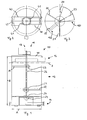
- FIG. 1 shows a longitudinal section through a schematically illustrated device 10 according to the invention for dissolving and / or suspending a solid in effluent through the device wastewater. It comprises the container 12 for receiving the solid, the inlet 14 through which the waste water can be introduced into the container and to the solid, the outlet 16 through which the solid dissolved and / or suspended in the wastewater can be diverted from the container, and the agitator 18 for mixing solid collected in the container and effluent introduced into the container through the inlet.
- the body of the container 12 is (circular) cylindrical.
- the height of the container is in the FIG. 1 indicated by the arrow H.
- the container 12 is arranged so that it stands on its base.
- the diameter of the container 12 is indicated by the arrow A.
- the inlet 14 is designed so that the waste water can be introduced into the center of the container.
- the distributor cone 24 is arranged for distributing the waste water supplied via the inlet 14 into the container in the container.
- the agitator 18 comprises the gear motor 19, which is preferably designed for 1 to 5, preferably about 2.5 revolutions per minute, the shaft 26 with a diameter of 40 mm, the two agitator blades 20 and 22 with the abutments 21 and 23 and the bearing 27.
- the bearing 27 is mounted on the three transverse struts 30, 31 and 32, which in Fig. 3 are shown. On the outer lateral surface of the cylindrical container treads (not shown) may be provided. Thus, the accessibility of the container can be improved.
- the solid which preferably comprises the above-described inorganic material is dispersed, preferably at least partially, particularly preferably completely dissolved. This is usually favored by carbonation in the wastewater.
- the dissolved constituents of the inorganic material can then be at least partially fixed on the activated sludge flake of a biological sewage treatment plant operated according to the aerobic activated sludge process.
- FIG. 2 shows a plan view of the device of FIG. 1 ,
- the geared motor 19 and the stirrer are fixed to the strut 40 and 41 on the device 10.
- FIG. 3 shows a plan view of the device of FIG. 1 in the amount of in the FIG. 1 shown partly dashed, partly dotted line 2.
- FIG. 4 shows the in FIG. 3 marked with the arrow 122 area of the stirring blade 22 in a schematic perspective view.
- the stirring blade 22 has a triangular cross-section.
- FIG. 5 shows the in FIG. 3 marked with the arrow 120 area of the stirring blade 20 in a schematic perspective view.
- the stirring blade 20 is formed as a circular disc sector. Particularly preferably, both stirring blades 20 and 22 have a shape as shown in the FIG. 5 is shown.
Landscapes
- Chemical & Material Sciences (AREA)
- Chemical Kinetics & Catalysis (AREA)
- Life Sciences & Earth Sciences (AREA)
- Environmental & Geological Engineering (AREA)
- Hydrology & Water Resources (AREA)
- Engineering & Computer Science (AREA)
- Water Supply & Treatment (AREA)
- Organic Chemistry (AREA)
- Health & Medical Sciences (AREA)
- Biodiversity & Conservation Biology (AREA)
- Microbiology (AREA)
- Medicinal Chemistry (AREA)
- Dispersion Chemistry (AREA)
- Removal Of Specific Substances (AREA)
Abstract
Description
- Die vorliegende Erfindung betrifft eine Vorrichtung zum Dispergieren, insbesondere zum Lösen und/oder Suspendieren, eines Feststoffs in durch die Vorrichtung leitbarem Abwasser sowie ihre Verwendung in einer Abwasserreinigungs- oder Kläranlage, insbesondere zur Erhöhung des pH-Werts des Abwassers oder Verringerung des Calcitlösevermögens des Abwassers. Außerdem kann mit ihr auf zuverlässige und einfache Weise eine Erhöhung der Versorgung einer nach dem aeroben Belebtschlammverfahren betriebenen biologischen Abwasserreinigungs-oder Kläranlage mit Calcium und Magnesium erreicht werden oder ein lösender Angriff von Beton in einer Abwasserreinigungs- oder Kläranlage verringert und zumindest teilweise oder sogar vollständig vermieden werden.
- Aus der
EP 1 741 679 A2 ist ein Verfahren bekannt zur verbesserten Versorgung von Abwasser mit Calcium und Magnesium. Dabei wird Belebtschlamm enthaltendes Abwasser aus der Biologie einer Abwasserreinigungsanlage oder Kläranlage in einen Reaktor, der einen anorganischen Feststoff, der in dem Abwasser dispergiert werden soll, eingedüst. Beim Betrieb eines solchen Reaktors hat sich gezeigt, dass ein kontinuierliches Dispergieren, insbesondere Lösen und/oder Suspendieren, des Feststoffs ohne Störungen nicht möglich ist. Der in den Reaktor gefüllte Feststoff wird nicht gleichmäßig dispergiert, sondern bevorzugt im Bereich der Eindüsung gelöst und/oder dispergiert. Im Bereich der Eindüsung wird daher der eingefüllte Feststoff schnell verbraucht. Der in den Reaktor gefüllte Feststoff formt sich dort trichterförmig. Ohne ständige Kontrollen durch Betriebspersonal und ein Auffüllen des Trichters mit neuem Feststoff oder Umverteilen des Feststoffs durch das Betriebspersonal ist ein störungsfreier Betrieb nicht möglich. Es kann daher leicht zu Verschlechterungen in der Reinigungs- oder Klärleistung solcher Abwasserreinigungs- oder Kläranlagen kommen. Durch den erhöhten Aufwand an manueller Nachfüll- oder Umverteilungsarbeit steigen die Kosten des Betriebs der gesamten Kläranlage. Ferner ist die gleichmäßige Versorgung des Abwassers mit Calcium und Magnesium nicht möglich. Dadurch kann eine vorteilhafte Erhöhung des pH-Werts des Abwassers, eine vorteilhafte Verringerung des Calcitlösevermögens des Abwassers, eine vorteilhafte Erhöhung der Versorgung einer nach dem aeroben Belebtschlammverfahren betriebenen biologischen Abwasserreinigungsanlage mit Calcium und Magnesium, eine positive Erhöhung des Gehalts an CaCO3 der Belebtschlammflocke einer nach dem aeroben Belebtschlammverfahren betriebenen biologischen Abwasserreinigungsanlage sowie die Verringerung oder Vermeidung eines lösenden Angriffs von Beton in der Abwasserreinigungs- oder Kläranlage nicht sichergestellt werden. - Der Versuch dieses Problem dadurch zu lösen, das Abwasser an mehreren Stellen in den Reaktor einzudüsen, erfordert, dass je weiterer Eindüsung eine zusätzliche Pumpe benötigt wird. Diese Ausgestaltung ist nicht nur konstruktiv deutlich aufwändiger und wegen der mehrfachen Eindüsung komplizierter zu steuern, sondern auch deutlich kostenintensiver, da mehrere Pumpen benötigt werden.
Ein anderer Versuch dieses Problem zu lösen, indem man das in den Reaktor eingeleitete Abwasser gegen eine halbkugelförmige Prallfläche strömen lässt, um das Abwasser gleichmäßig im Reaktor und in dem eingefüllten Feststoff zu verteilen führte ebenfalls zu den oben bereits beschriebenen "Trichtern" in dem Feststoff und zu einer ungleichmäßigen Dispersion des Feststoffs, so dass auch hier nicht auf ständige Kontrollen und häufiges manuelles Nachfüllen oder Umverteilen des Feststoffs durch das Betriebspersonal verzichtet werden konnte. - Die Aufgabe der vorliegenden Erfindung ist es daher, die Nachteile aus dem Stand der Technik zu vermeiden oder zu beseitigen und insbesondere eine Vorrichtung bereitzustellen mit der auf zuverlässige, einfache und kostengünstige Weise ein Feststoff gleichmäßig und kontinuierlich in Abwasser dispergiert, vorzugsweise gelöst, werden kann, um eine Abwasserreinigungs- oder Kläranlage weniger arbeits-und kostenaufwändig sowie mit verbesserter Reinigungs- oder Klärleistung betreiben zu können. Insbesondere soll eine Erhöhung des pH-Werts des Abwassers, eine vorteilhafte Verringerung des Calcitlösevermögens des Abwassers, eine vorteilhafte Erhöhung der Versorgung einer nach dem aeroben Belebtschlammverfahren betriebenen biologischen Abwasserreinigungsanlage mit Calcium und Magnesium sowie eine positive Erhöhung des Gehalts an CaCO3 der Belebtschlammflocke einer nach dem aeroben Belebtschlammverfahren betriebenen biologischen Abwasserreinigungsanlage erreicht werden können.
- Diese Aufgabe wird durch die Vorrichtung nach Anspruch 1 sowie die Verwendung nach Anspruch 18 gelöst. Bevorzugte vorteilhafte Ausführungsformen finden sich in den jeweiligen Unteransprüchen.
- Die erfindungsgemäße Vorrichtung nach Anspruch 1 umfasst zum Dispergieren, insbesondere Lösen und/oder Suspendieren, eines Feststoffs in durch die Vorrichtung leitbarem Abwasser:
- (a) einen Behälter zur Aufnahme des Feststoffs,
- (b) einen Zulauf durch den das Abwasser in den Behälter und zu dem Feststoff einleitbar ist,
- (c) einen Ablauf durch den der in dem Abwasser gelöste und/oder suspendierte Feststoff aus dem Behälter ableitbar ist, und
- (d) eine Rühreinrichtung zum Mischen von in dem Behälter aufgenommenem Feststoff und durch den Zulauf in den Behälter eingeleitetem Abwasser.
Mit dieser Vorrichtung kann ein gleichmäßiges und kontinuierliches Dispergieren, vorzugsweise ein Lösen, des Feststoffs in dem Abwasser erreicht werden. Diese Vorrichtung kann vorteilhaft in einer Abwasserreinigungs- oder Kläranlage verwendet werden, insbesondere um Magnesium und Calcium in dem Abwasser zu lösen. Damit kann eine vorteilhafte Erhöhung des pH-Werts des Abwassers, eine vorteilhafte Verringerung des Calcitlösevermögens des Abwassers, eine vorteilhafte Erhöhung der Versorgung einer nach dem aeroben Belebtschlammverfahren betriebenen biologischen Abwasserreinigungsanlage mit Calcium und Magnesium sowie eine positive Erhöhung des Gehalts an CaCO3 der Belebtschlammflocke einer nach dem aeroben Belebtschlammverfahren betriebenen biologischen Abwasserreinigungs- oder Kläranlage erreicht werden. - Die Vorrichtung der Erfindung kann zusätzlich eine Pumpe zum Pumpen des Abwassers durch den Zulauf in den Behälter und des in dem Abwasser gelösten und/oder suspendierten Feststoffs durch den Ablauf aus dem Behälter umfassen. Damit kann die Vorrichtung so angeordnet sein, dass das Abwasser entgegen der Schwerkraft durch den Behälter pumpbar ist. Dies hat den Vorteil, dass die Vorrichtung so angeordnet werden kann, dass der Behälter nach oben hin offen ist. Durch diese Öffnung kann auf einfache Weise der Feststoff in den Behälter gefüllt werden und mit Hilfe der Schwerkraft im Wesentlichen gleichmäßig in dem Behälter verteilt werden, bevorzugt auch während eines kontinuierlichen Betriebs der Vorrichtung. Die erfindungsgemäße Vorrichtung kann jedoch auch liegend angeordnet sein.
- Der Zulauf der Vorrichtung kann eine Rückschlagklappe aufweisen. Dies ist vorteilhaft, wenn eine Betriebsstörung eintritt, da so vermieden werden kann, dass noch nicht gelöster oder noch nicht suspendierter Feststoff in die Pumpe gelangt, die bevorzugt vorgesehen ist.
- Die Rühreinrichtung kann mindestens ein Rührblatt aufweisen. Anstellte eines Rührblattes können jedoch beliebige andere Rührwerkzeuge eingesetzt werden, z. B. eine Rührschnecke. Besonders bevorzugt weist die erfindungsgemäße Vorrichtung zwei Rührblätter auf. Mit zwei Rührblättern wird ein operativer Nutzen erzielt zwischen apparativem Aufwand und Leistung hinsichtlich der gleichmäßigen und kontinuierlichen Dispersion des Feststoffs in dem Abwasser.
- Die erfindungsgemäße Vorrichtung weist als Behälter vorzugsweise einen zylinderförmigen Körper auf. Damit kann am besten ein gleichmäßiges und kontinuierliches Lösen und/oder Suspendieren mit einer Rühreinrichtung erzielt werden, die ein rotierendes Rührwerk, vorzugsweise mindestens ein Rührblatt, einsetzt.
- Die erfindungsgemäße Vorrichtung kann einen Behälter umfassen, der eine Höhe von bis zu 4 m, vorzugsweise etwa 2,0 bis 2,5 m, besonders bevorzugt etwa 2,2 m, und einen Durchmesser von bis zu 3 m, vorzugsweise 1,0 bis 1,5 m, besonders bevorzugt etwa 1,2 m, aufweist. Mit diesen Dimensionen kann die Vorrichtung in Abwasserreinigungs- oder Kläranlagen für bis zu 60.000 Einwohnereinheiten genutzt werden. Entsprechend der geplanten Nutzung können die Dimensionen der erfindungsgemäßen Vorrichtung angepasst werden. Für bis zu 20.000 Einwohnereinheiten einer Abwasserreinigungs- oder Kläranlage beträgt die Höhe des Behälters vorzugsweise 2,0 bis 2,5 m, und der Durchmesser des Behälters beträgt vorzugsweise von 1,0 bis 1,5 m. Bei dieser Größenordnung ist ein Rührblatt in der Regel ausreichend und bevorzugt.
- Vorzugsweise ist der Zulauf so ausgebildet, dass das Abwasser in die Mitte des Behälters einleitbar ist. Damit kann für eine gleichmäßige und kontinuierliche Dispersion des Feststoffs im Abwasser auf mehrere Pumpen verzichtet werden, da eine Pumpe allein dann ausreichend ist.
- Bei einer bevorzugten Ausführungsform der Erfindung umfasst die erfindungsgemäße Vorrichtung zusätzlich eine Verteilungseinrichtung, vorzugsweise einen Verteilerkegel, zur Verteilung des über den Zulauf in den Behälter zugeführten Abwassers in dem Behälter.
- Die erfindungsgemäße Vorrichtung kann aus gewöhnlichem Stahl gefertigt werden, wenn eine ausreichende Stärke, gegebenenfalls eine Verschleißschicht vorgesehen wird, vorzugsweise ist sie jedoch aus nichtrostendem Stahl gefertigt. Die Wandstärke des Behälters der erfindungsgemäßen Vorrichtung kann bis zu 6 mm, vorzugsweise etwa 3 mm, betragen.
- Die Rühreinrichtung der erfindungsgemäßen Vorrichtung kann eine Welle mit einem Durchmesser von bis zu 80 mm, vorzugsweise etwa 40 mm, aufweisen.
- Bei einer bevorzugten Ausführungsform enthält das Abwasser Belebtschlamm, vorzugsweise in einem Trockenmassegehalt von 0,01 % bis 15 %, besonders bevorzugt in einem Trockenmassegehalt von 0,1 % bis 2 %.
- Der nach völliger Austrocknung von Schlämmen übrig bleibende Rest wird Trockenmasse genannt. Der Trockenmassegehalt (TS), auch Trockensubstanzgehalt genannt, ergänzt sich mit dem Wassergehalt (W) zu 100%: TS + W = 100%.
- Bei einer bevorzugten Ausführungsform der Erfindung enthält das Abwasser eine Säure, besonders bevorzugt Kohlensäure. Denn die Vorrichtung der Erfindung kann dann auch verwendet werden zur Verringerung oder Vermeidung von Verschleiß von Beton durch einen lösenden Angriff. Insbesondere kann Beton einer ein Betonbecken umfassenden Abwasserreinigungsanlage oder Kläranlage geschützt werden, vor allem von mit Abwasser in Kontakt kommenden Wänden des Betonbeckens.
- Ein lösender Angriff von Beton kann durch Säuren, insbesondere in Abwasser verdünnte, anorganische und organische Säuren, Fett und Öle sowie durch austauschfähige Salze erfolgen.
- Der Angriff durch Säuren ist abhängig von der Konzentration der gelösten Säure und ihrer Stärke.
- Starke Säuren, wie Mineralsäuren, z. B. Salzsäure, Salpetersäure und Schwefelsäure, liegen in Wasser vollständig dissoziiert vor. Der pH-Wert einer starken Säure ergibt sich aus der Konzentration der Säure und lässt sich aus der Konzentration der Protonen berechnen. Starke Säuren können alle Bestandteile eines Zementsteins unter Bildung von Calcium-, Aluminium- und Eisensalzen sowie Kieselgel auflösen. Starke Säuren sind gemäß dieser Beschreibung solche Säuren, die einen pKs-Wert, der auch protochemisches Normalpotential eines Brönstedschen Säure-Base-Systems genannt wird, von < 0, vorzugsweise im Bereich von -7,0 bis
- 1,00, aufweisen. Die Säure HCl weist z.B. für das Säure-Base-System HCl ⇆ H+ + Cl- einen pKs-Wert von -7,0 auf. Die Schwefelsäure weist für das Säure-Base-System H2SO4 ⇆ H+ + HSO4 --einen pKs-Wert von -3,0 auf. Die Salpetersäure weist für das Säure-Base-System HNO3 ⇆ H+ + NO3 -einen pKs-Wert von
- 1,37 auf.
- Schwache Säuren liegen in Wasser nicht vollständig dissoziiert vor. Bei der Berechnung des pH-Wertes einer schwachen Säure muss deshalb ihr pKs-Wert berücksichtigt werden. Schwache Säuren sind gemäß dieser Beschreibung solche Säuren, die einen pKs-Wert im Bereich von 1,90 bis 9,5 aufweisen, vorzugsweise im Bereich von 3,5 bis 7, besonders bevorzugt im Bereich von 4,75 bis 6,5. Kohlensäure ist beispielsweise eine schwache Säure, die sich nur zu 0,1 % in Wasser löst. Ihr pKs-Wert weist für das Säure-Base-System CO2 + H2O ⇆ H+ + HCO3 - einen pKs-Wert von 6,35 auf. Weitere schwache Säuren sind beispielsweise Essigsäure mit einem pKs-Wert von 4,75 für das Säure-Base-System CH3CO2H ⇆ H+ + CH3CO2 -sowie Milchsäure mit einem pKs-Wert von 3,73.
- Eine schwache Säure reagiert mit Ca(OH)2, basischen Hydratphasen und mit Carbonaten, zum Beispiel mit Kalkstein (CaCO3), unter Bildung von wasserlöslichem Calciumhydrogencarbonat. Sie kann mit der Tonerde und dem Eisenoxid des Zementes keine löslichen Salze (Hydrogencarbonate) bilden. Beim Einwirken von Kohlensäure, insbesondere Kalk lösender Kohlensäure, auf Zementstein bleiben daher Aluminium- und Eisenhydroxid bzw. Eisen- oder Aluminiumoxidhydrat zurück.
- Die Abgase zahlreicher Brennstoffe, z. B. Kohle und Heizöl, enthalten Schwefeldioxid (SO2), das mit Wasser schweflige Säure bildet. Obwohl die Konzentration von Schwefeldioxid in der Luft wesentlich geringer ist als diejenige von Kohlendioxid bezogen auf die Einwirkungsdauer von Kohlendioxid (Kohlensäure), wird wegen der größeren Säurestärke der schwefligen Säure Beton angegriffen, allerdings zeigen sich Schäden (Abmehlen der Betonaußenschicht) erst nach längerer Einwirkungsdauer. Moorböden können Eisensulfide (z. B. Pyrit) enthalten, die nach Oxidation des Schwefels in Gegenwart von Wasser schweflige Säure bilden. Da letztere dann in wesentlich größerer Konzentration als in der Luft vorliegt, werden Betonbauteile dadurch auch wesentlich rascher angegriffen. Darüber hinaus können durch Weiteroxidation des Sulfits mit Luftsauerstoff auch Sulfate gebildet werden, die bei Betonbauwerken zu einem treibenden Angriff führen.
- Schwefelwasserstoff (H2S) ist ebenfalls eine schwache Säure, die Beton im Gasraum von Abwasserreinigungsanlagen oberhalb des Wasserspiegels angreifen kann. Der pKs-Wert beträgt 6,99 für das Säure-Base-System H2S ⇆ H+ + HS-. Voraussetzung für eine biogene Schwefelsäurekorrosion (BSK) ist jedoch das Vorhandensein von organischen und anorganischen Schwefelverbindungen im Abwasser bzw. in der sogenannten Sielhaut von Abwasserleitungen. Schwefelwasserstoff wird z. B. aus Sulfaten in Gegenwart von sulfatreduzierenden Bakterien gebildet, wenn das Abwasser durch Sauerstoffmangel vom aeroben in den anaeroben Zustand übergeht. Dieser Prozess wird durch höhere Temperaturen und durch fallenden pH-Wert des Abwassers beschleunigt. Derartige Bedingungen treten besonders bei Abwasseranlagen in heißen Ländern auf, haben aber auch in Ländern, wie Deutschland, Schweiz und Österreich, zu erheblichen Schäden in Abwassersystemen, wie Abwasserrohrsystemen oder in Abwasserreinigungsanlagen, geführt. Der Schwefelwasserstoff entweicht, verstärkt im Bereich turbulenter Strömung, in den Gasraum über dem Abwasserspiegel, und kann auf feuchten Betonoberflächen in Anwesenheit von Luftsauerstoff und unter der Wirkung von aeroben Mikroorganismen, z.B. Thiobakterien, wie Thiobazillus concretivorus, Schwefelsäure bilden. Dabei sind neben den angebotenen Schwefelwasserstoffmengen vor allem die Temperaturen in dem Abwasser maßgebend, da die mikrobiologisch gesteuerten Oxidationsvorgänge des Schwefelwasserstoffes zur Schwefelsäure am schnellsten bei Temperaturen von etwa 30 °C ablaufen. Es kann aber schon oberhalb von 18 °C aus Schwefelwasserstoff in Gegenwart von Sauerstoff und Feuchtigkeit eine sehr stark angreifende 6-prozentige Schwefelsäure mit einem pH-Wert von 0,1 gebildet werden. Durch die Schwefelsäure wird der basische Zementstein des Betons und gegebenenfalls carbonatischer Zuschlag einem lösenden Angriff unterzogen. Durch Gips- und Ettringitausscheidungen im Betongefüge kommt es gleichzeitig zu einem treibenden Angriff. Bisher wurde als vorbeugende Maßnahmen gegen Schwefelwasserstoffentwicklung in Abwassersystemen vorgeschlagen in den Abwassersystemen ein gleichmäßiges und ausreichendes Gefälle der Rohrleitungen, keine Turbulenzen, keine Totbereiche zur Vermeidung von Schlammbildung und eine gute Belüftung vorzusehen.
- Der lösende Angriff von Fetten und Ölen, z.B. pflanzlichen Fetten und Ölen, die Glycerinester mehrfach ungesättigter Fettsäuren darstellen, auf Beton kann dadurch erfolgen, dass sie durch das Calciumhydroxid des Zementsteins verseift werden, indem die Ester durch Wasseraufnahme gespalten werden. Die fettsauren Calciumsalze sind wasserlöslich und führen zur Schwächung des Betongefüges. Insbesondere bei höheren Temperaturen werden Betone durch pflanzliche Fette und Öle stark angegriffen.
- Zu den austauschfähigen Salzen, die Beton lösend angreifen können, gehören vor allem Magnesium- und Ammoniumsalze, wie Magnesiumchlorid und Ammoniumchlorid. Sie greifen den Beton an, indem sie einerseits mit dem Kalkhydrat des Zementsteins leicht lösliche Chloride bilden. Beim Einwirken von Ammoniumchlorid auf basischen Zementstein kann Ammoniak in gasförmiger Form entweichen. Dadurch kann eine Neutralisation des Calciumhydroxids erfolgen, wobei zusätzlich leicht lösliches Calciumchlorid gebildet wird. Chloridquellen sind Meerwasser, Salzlagerstätten, Tausalzlösungen und Chlorwasserstoff. Chlorwasserstoff wird beispielsweise bei einer durch Brand verursachten Zersetzung von Polyvinylchlorid (PVC) in Rohrleitungen, Kabelummantelungen, Fensterrahmen und Behältern aus PVC freigesetzt und mit Löschwasser in Salzsäure umgewandelt. Bei Berührung mit Beton reagieren die Salzsäuredämpfe mit dem Zementstein unter Bildung von Calciumchlorid, welches sich zunächst in der Betonaußenzone anreichert.
- Eine der bedeutendsten Ursachen eines lösenden Angriffs von Beton ist jedoch der Angriff durch Kohlensäure, insbesondere freier Kalk lösender Kohlensäure. Bisher von der Österreichischen Vereinigung für Beton- und Bautechnik vorgeschlagene Maßnahmen gegen den Angriff von Kohlensäure, insbesondere Kalk lösender Kohlensäure, auf Beton betreffen Maßnahmen, die hauptsächlich den Beton selbst betreffen. So wurde vorgeschlagen eine Einplanung einer erhöhten Betondeckung bei Neuanlagen als Verschleißschicht vorzusehen, bei der Herstellung von Beton Bindemittel mit einem geringen Ca(OH)2-Gehalt im erhärteten Zementstein einzusetzen und kein Kalksteinmehl als Zusatzstoff zu verwenden. Siehe dazu "Neue Lösungen für Kläranlagenbeton" in bau.zeitung 6/07, Seiten 33 bis 36. Diese Maßnahmen, die den Beton selbst betreffen haben den Nachteil, dass sie nur für den Bau von neuen Abwasserreinigungsanlagen oder Kläranlagen eingesetzt werden können oder bei einer grundlegenden Sanierung solcher Anlagen. Bei Anlagen, die bereits im Betrieb sind und ohne Sanierung weiter betrieben werden müssen, können diese Maßnahmen nicht angewendet werden.
- Ferner wurde eine Schutzschicht aus Kunststoff oder auf Silikatbasis vorgeschlagen, z. B. durch eine Nachbehandlung von Beton mit Epoxid- oder Acrylatfilmen oder eine Imprägnierung auf Silikatbasis. Eine solche Schutzschicht kann zwar den tatsächlichen Angriff verhindern, eine solche Schutzschicht ist jedoch aufwändig und kostenintensiv. Außerdem kann durch eine lokale Beschädigung der Schutzschicht dennoch eine Beschädigung auftreten, die längere Zeit unerkannt bleibt und so zu einem signifikanten Angriff des Betons führen. In dem oben bereits genannten Artikel
- "Neue Lösungen für Kläranlagenbeton" in bau.zeitung 6/07, Seiten 33 bis 36, wird beschrieben, dass eine erhebliche Zahl von Abwasserreinigungsanlagen oder Kläranlagen Betonschäden aufweisen und insbesondere Dichteschäden aufweisen. Das Aufbringen einer Schutzschicht kann aber ebenfalls nur bei neuen Anlagen oder bei Altanlagen nur durch eine Unterbrechung des Betriebs des Systems durchgeführt werden. Dies ist besonders bei Abwasserreinungunsanlagen oder Kläranlagen, Kanalisationssystemen, Abwasserrohren nachteilig, da den Betreibern oft nur eine einzige Anlage zur Verfügung steht.
- Der lösende Angriff kann vorzugsweise dann vermieden werden, wenn mit der erfindungsgemäßen Vorrichtung ein Feststoff dispergiert, vorzugsweise gelöst, wird, der für ein anorganisches Material steht, das sowohl Calcium als auch Magnesium enthält. Dieses calcium- und magnesiumhaltige Material enthält ferner ein Carbonat, Hydrogencarbonat, Oxid oder Hydroxid oder eine Mischung von zwei oder mehreren dieser Anionen. Neben diesen erfindungsgemäßen Bestandteilen kann das anorganische Material noch andere Bestandteile aufweisen, die im Folgenden auch als Nebenbestandteile bezeichnet werden. Diese Nebenbestandteile sind z. B. die Oxide von Silicium, Aluminium, Eisen, Kalium, Titan und Phosphor, die jeweils in Mengen von 0,05 bis 0,3 Gewichtsprozent vorliegen können. Ferner können in Spurenmengen von bis zu 100 ppm Chloride, Fluoride und verschiedene Metalle als weitere Nebenbestandteile enthalten sein. Die Nebenbestandteile machen in der Regel jedoch weniger als 5 Gew.-% des anorganischen Materials aus, vorzugsweise weniger als 2 Gew.-% und besonders bevorzugt weniger als 1 Gew.-%. Das anorganische Material kann zum Beispiel eine beliebige Mischung von Calciumcarbonat und Magnesiumhydrogencarbonat enthalten oder eine beliebige Mischung von Calciumoxid und Magnesiumhydroxid, oder es kann Dolomit enthalten. Vorzugsweise enthält das anorganische Material CaCO3, MgO, MgCO3 und CaO, besonders bevorzugt CaCO3, MgO und MgCO3, ganz besonders bevorzugt thermisch behandelten Dolomit. Besonders bevorzugt findet durch Verwendung der erfindungsgemäßen Vorrichtung eine chemische Auflösung des Feststoffs in dem Abwasser statt.
- Mit der erfindungsgemäßen Vorrichtung kann daher der Verschleiß von Beton durch einen lösenden Angriff verringert oder teilweise oder sogar vollständig vermieden werden.
- Das anorganische Material kann mit Wasser und/oder Kohlendioxid zu Ca(OH)2, Mg(OH)2, Ca(HCO3)2, Mg(HCO3)2 reagieren. Sobald diese Spezies im Abwasser vorliegen, wird insbesondere das Gleichgewicht der Lösungsreaktionen des lösenden Angriff einer Säure, insbesondere der Kohlensäure, von Beton zu ungunsten der Lösungsreaktion beeinflusst und somit der lösende Angriff von Beton verringert oder sogar ganz vermieden. Damit wird vor allem Beton geschützt, der unmittelbar mit Abwasser in Kontakt kommt, aber auch Beton über einem Wasserspiegel wird geschützt, da dieser Beton durch Säuren angegriffen werden kann, die ihn über die Gasphase angreifen, z. B. wie oben in Bezug auf den Angriff durch H2S erläutert. Der lösende Angriff von Fetten und Ölen wird durch das anorganische Material, das durch die erfindungsgemäße Vorrichtung zumindest teilweise gelöst werden kann, insbesondere dadurch verringert oder sogar ganz vermieden, dass die Calcium- und Magnesiumkomponenten mit Abwasser in ausreichendem Umfang Calcium- und Magnesiumhydroxid bilden, welche die Ester in den Fetten und Ölen spalten können ohne dass dafür Calciumhydroxid aus dem Beton herausgelöst wird.
- Ferner wird insbesondere durch die Magnesiumkomponente des anorganischen Materials vor allem der Angriff durch austauschfähige Salze verringert oder sogar ganz vermieden. Gelöstes Magnesium kann sich an Beton, der im Wesentlichen basisch reagiert, als Brucit (Mg(OH)2) abscheiden und so eine den lösenden Angriff hemmende Schicht bilden.
- Damit kann besonders vorteilhaft der Beton von Abwasserreinungunsanlagen oder Kläranlagen oder anderen Systemen, die mit Abwasser in Berührung kommen, insbesondere solche durch die Abwasser geleitet wird, vor einem lösenden Angriff ohne Unterbrechung des Betriebs geschützt werden. Dies hat den Vorteil, dass ältere Anlagen baulich nicht nachgebessert werden müssen. Bei Neuanlagen kann auf die bisher vorgeschlagenen Maßnahmen, die den Beton selbst betreffen, verzichtet werden. Ferner kann auf aufwändige und teure Beschichtungen mit Kunststoffen oder Silikaten verzichtet werden. Bei Anlagen für besonders aggressive Abwässer kann die Erfindung aber auch zusammen mit den bisher vorgeschlagenen Maßnahmen, die den Beton selbst betreffen, und/oder den vorgeschlagenen Schutzschichten gemeinsam eingesetzt werden.
- Die Erfindung kann besonders den Verschleiß von Beton durch den lösenden Angriff einer Säure, vorzugsweise der Kohlensäure, verringern oder sogar ganz vermeiden. Damit kann besonders vorteilhaft der Beton der Wände eines Belebungs- und/oder Nachklärbeckens in einer Abwasserreinigungsanlage mit Nitrifikation und Denitrifikation geschützt werden. Es hat sich nämlich gezeigt, dass insbesondere in Belebungs- und Nachklärbecken hohe Kohlensäurekonzentrationen auftreten können, vor allem bei Abwasserreinungunsanlagen oder Kläranlagen mit Nitrifikation und Denitrifikation.
- Bei einer bevorzugten Ausführungsform wird nur ein Teilvolumenstrom von Abwasser, gegebenenfalls auch Belebtschlamm einer nach dem aeroben Belebtschlammverfahren betriebenen biologischen Abwasserreinungsanlage oder Kläranlage, durch die erfindungsgemäße Vorrichtung geleitet, die als Feststoff das oben beschriebene anorganische Material enthält. In der erfindungsgemäßen Vorrichtung wird das anorganische Material vorzugsweise zumindest teilweise in Wasser gelöst. Bevorzugt werden als Teilvolumenstrom des Abwassers, vorzugsweise mit Belebtschlamm, 1 bis 100 %, insbesondere 1 bis 20 %, des Zulaufvolumenstroms der Abwasserreinigungsanlage, an einer geeigneten Stelle dem Klärprozess entnommen und durch die erfindungsgemäße Vorrichtung geleitet. Der in die erfindungsgemäße Vorrichtung eingeleitete Teilvolumenstrom des Abwassers oder Belebtschlamms wird mit dem Feststoff durch die Vorrichtung nach Anspruch 1 gleichmäßig und konstant in einen intensiven Kontakt gebracht. Das Abwasser, vorzugsweise mit Belebtschlamm, kann im freien Ablauf aus der Vorrichtung heraus und in das System der Abwasserreinigungsanlage oder Kläranlage, beispielsweise in ein Belebtschlammbecken, zurück geführt werden. Im Kontakt mit dem Abwasser, das vorzugsweise Belebtschlamm enthält, kann es zu einer ausreichenden Umwandlung der Inhaltsstoffe des anorganischen Materials zu Ca(OH)2, Mg(OH)2, Ca(HCO3)2, Mg(HCO3)2 sowie verwandten Verbindungen kommen. Die Stoffe werden im Laufe der Betriebszeit vollständig gelöst und können sich an den Wänden der Anlage abscheiden aber auch an die Belebtschlammflocke anlagern. Dadurch kann vorteilhaft auch die Flockenstruktur von Belebtschlamm stabilisiert werden, wobei der Gehalt an CaCO3 der Flocke steigt. Auf diese Weise kann neben dem Schutz der Betonwände auch der Schlamm behandelt und in seiner Struktur stabilisiert werden. Dadurch kann besonders vorteilhaft auch eine Bildung von Schwimmschlamm und Blähschlamm vermieden oder verhindert werden. Darüber hinaus können sich weitere Vorteile einstellen, wie ein verbessertes Absetzverhalten im Nachklärbecken, eine Stabilisierung der Nitrifikation, ein Ausgasen von Kohlensäure im Faulturm ohne Schaumbildung oder Spucken.
- Der Feststoff kann in einer Korngröße < 20 mm, bevorzugt 2 bis 12 mm, vorliegen.
- Die Schütthöhe des Feststoffs in dem Behälter kann in Abhängigkeit von den Dimensionen der erfindungsgemäßen Vorrichtung 20 bis 400 cm, bevorzugt 60 bis 250 cm, betragen. Ein gesicherter Betrieb ist insbesondere bei einer Beschickung der erfindunsgemäßen Vorrichtung mit 1 bis 30 m3, bevorzugt 5 bis 15 m3, Abwasser, vorzugsweise mit Belebtschlamm, pro Stunde und m2 Querschnittsfläche der Vorrichtung möglich.
- Anstelle einer einzigen erfindungsgemäßen Vorrichtung kann auch eine Serie von Vorrichtungen bzw. eine Vorrichtungskaskade eingesetzt werden.
- Die erfindungsgemäße Vorrichtung wird daher vorteilhaft in einer Abwasserreinigungs- oder Kläranlage verwendet.
- Durch ihre Verwendung in einer Abwasserreinigungs- oder Kläranlage kann insbesondere eine vorteilhafte Erhöhung des pH-Werts des Abwassers, eine vorteilhafte Verringerung des Calcitlösevermögens des Abwassers, eine Erhöhung der Versorgung einer nach dem aeroben Belebtschlammverfahren betriebenen biologischen Abwasserreinigungsanlage mit Calcium und Magnesium sowie eine Erhöhung des Gehalts an CaCO3 der Belebtschlammflocke einer nach dem aeroben Belebtschlammverfahren betriebenen biologischen Abwasserreinigungsanlage erreicht werden.
- Das Calcitlösevermögen oder die Calcit-Sättigung, was im Folgenden als CLV abgekürzt wird, betrifft das Kalk-Kohlensäure-Gleichgewicht. Die Berechnung des CLV erfolgt durch die Berechnung des Sättigungs-pH-Wertes nach Strohecker und Langelier gemäß der DIN 38404 Teil 10 R 2. Ein negatives Calcitlösevermögen bedeutet, dass nach dem Kalk-Kohlensäure-Gleichgewicht Calciumcarbonat abgeschieden wird. Bei einer nach dem Belebtschlammverfahren betriebenen biologischen Abwasserreinigungsanlage bedeutet ein verringertes CLV, dass die erfindungsgemäße Vorrichtung für die Abwasserreinigungsanlage vorteilhaft ausreichend Calcium und gegebenenfalls Magnesium bereitstellt.
-
- Figur 1
- einen Längsschnitt durch eine schematisch dargestellte erfindungsgemäße Vorrichtung;
- Figur 2
- eine Draufsicht auf die Vorrichtung der
Figur 1 ; - Figur 3
- eine Draufsicht auf die Vorrichtung der
Figur 1 in Höhe der Linie 2; - Figur 4
- eine schematische Perspektivansicht auf den Bereich 122 des Rührblatts 22 in
Figur 3 ; und - Figur 5
- eine schematische Perspektivansicht auf den Bereich 120 des Rührblatts 20 in
Figur 3 . - In den verschiedenen Figuren sind entsprechende Bauteile, Elemente und Gegenstände mit gleichen Bezugszeichen versehen.
- Die
Figur 1 zeigt einen Längsschnitt durch eine schematisch dargestellte erfindungsgemäße Vorrichtung 10 zum Lösen und/oder Suspendieren eines Feststoffs in durch die Vorrichtung leitbarem Abwasser. Sie umfasst den Behälter 12 zur Aufnahme des Feststoffs, den Zulauf 14 durch den das Abwasser in den Behälter und zu dem Feststoff einleitbar ist, den Ablauf 16 durch den der in dem Abwasser gelöste und/oder suspendierte Feststoff aus dem Behälter ableitbar ist, und die Rühreinrichtung 18 zum Mischen von in dem Behälter aufgenommenem Feststoff und durch den Zulauf in den Behälter eingeleitetem Abwasser. Der Körper des Behälters 12 ist (kreis)zylinderförmig ausgebildet. Die Höhe des Behälters ist in derFigur 1 durch den Pfeil H angegeben. Der Behälter 12 ist so angeordnet, dass er auf seiner Grundfläche steht. Der Durchmesser des Behälters 12 ist durch den Pfeil A angegeben. Der Zulauf 14 ist so ausgebildet, dass das Abwasser in die Mitte des Behälters einleitbar ist. Über dem Zulauf 14 ist der Verteilerkegel 24 angeordnet zur Verteilung des über den Zulauf 14 in den Behälter zugeführten Abwassers in dem Behälter. Die Rühreinrichtung 18 umfasst den Getriebemotor 19, der vorzugsweise für 1 bis 5, vorzugsweise etwa 2,5, Umdrehungen pro Minute ausgelegt ist, die Welle 26 mit einem Durchmesser von 40 mm, die zwei Rührblätter 20 und 22 mit den Gegenlagern 21 und 23 sowie das Lager 27. Das Lager 27 ist auf den drei Querstreben 30, 31 und 32 befestigt, die inFig. 3 gezeigt sind. An der äußeren Mantelfläche des zylinderförmigen Behälters können Trittstufen (nicht gezeigt) vorgesehen sein. Damit kann die Zugänglichkeit des Behälters verbessert werden. Mit der erfindungsgemäßen Vorrichtung kann bei einer bevorzugten Ausführungsform der Erfindung der Feststoff, der vorzugsweise das oben beschriebene anorganische Material umfasst, dispergiert, bevorzugt zumindest teilweise, besonders bevorzugt vollständig, gelöst werden. Dies wird in der Regel begünstigt durch Kohlensäure in dem Abwasser. Besonders bevorzugt können dann die gelösten Bestandteile des anorganischen Materials zumindest teilweise auf der Belebtschlammflocke einer nach dem aeroben Belebtschlammverfahren betriebenen biologischen Abwasserreinigungsanlage fixiert werden. - Die
Figur 2 zeigt eine Draufsicht auf die Vorrichtung derFigur 1 . Der Getriebemotor 19 und die Rühreinrichtung sind mit den Streben 40 und 41 an der Vorrichtung 10 befestigt. - Die
Figur 3 zeigt eine Draufsicht auf die Vorrichtung derFigur 1 in Höhe der in derFigur 1 gezeigten teils gestrichelt, teils punktierten Linie 2. - Die
Figur 4 zeigt den inFigur 3 mit dem Pfeil 122 gekennzeichneten Bereich des Rührblatts 22 in einer schematischen Perspektivansicht. Das Rührblatt 22 weist einen dreiecksförmigen Querschnitt auf. - Die
Figur 5 zeigt den inFigur 3 mit dem Pfeil 120 gekennzeichneten Bereich des Rührblatts 20 in einer schematischen Perspektivansicht. Das Rührblatt 20 ist als Kreisscheibensektor ausgeformt. Besonders bevorzugt weisen beide Rührblätter 20 und 22 eine Form auf, wie sie in derFigur 5 dargestellt ist.
Claims (23)
- Vorrichtung (10) zum Lösen und/oder Suspendieren eines Feststoffs in durch die Vorrichtung leitbarem Abwasser, umfassend:(a) einen Behälter (12) zur Aufnahme des Feststoffs,(b) einen Zulauf (14) durch den das Abwasser in den Behälter und zu dem Feststoff einleitbar ist,(c) einen Ablauf (16) durch den der in dem Abwasser gelöste und/oder suspendierte Feststoff aus dem Behälter ableitbar ist, und(d) eine Rühreinrichtung (18) zum Mischen von in dem Behälter aufgenommenem Feststoff und durch den Zulauf in den Behälter eingeleitetem Abwasser.
- Vorrichtung nach Anspruch 1, zusätzlich umfassend(e) eine Pumpe zum Pumpen des Abwassers durch den Zulauf in den Behälter und des in dem Abwasser gelösten und/oder suspendierten Feststoffs durch den Ablauf aus dem Behälter.
- Vorrichtung nach Anspruch 1 oder 2, die so angeordnet ist, dass das Abwasser entgegen der Schwerkraft durch den Behälter pumpbar ist.
- Vorrichtung nach einem vorstehenden Anspruch, wobei der Zulauf eine Rückschlagklappe aufweist.
- Vorrichtung nach einem vorstehenden Anspruch, wobei die Rühreinrichtung mindestens ein Rührblatt (20), vorzugsweise zwei Rührblätter (20; 22), aufweist.
- Vorrichtung nach einem vorstehenden Anspruch, wobei der Behälter einen zylinderförmigen Körper aufweist.
- Vorrichtung nach einem vorstehenden Anspruch, wobei die Wandstärke des Behälters bis zu 6 mm, vorzugsweise etwa 3 mm, beträgt
- Vorrichtung nach einem vorstehenden Anspruch, wobei der Behälter eine Höhe von bis zu 4 m, vorzugsweise etwa 2,0 bis 2,5 m, besonders bevorzugt etwa 2,2 m, und einen Durchmesser von bis zu 3 m, vorzugsweise 1,0 bis 1,5 m, besonders bevorzugt etwa 1,2 m, aufweist.
- Vorrichtung nach einem vorstehenden Anspruch, wobei der Zulauf so ausgebildet ist, dass das Abwasser in die Mitte des Behälters einleitbar ist.
- Vorrichtung nach einem vorstehenden Anspruch, zusätzlich umfassend:(f) einen Verteilerkegel (24), zur Verteilung des über den Zulauf in den Behälter zugeführten Abwassers in dem Behälter.
- Vorrichtung nach einem vorstehenden Anspruch, die aus nichtrostendem Stahl gefertigt ist.
- Vorrichtung nach einem vorstehenden Anspruch, wobei die Rühreinrichtung eine Welle (26) mit einem Durchmesser von bis zu 80 mm, vorzugsweise etwa 40 mm, aufweist.
- Vorrichtung nach einem vorstehenden Anspruch, wobei das Abwasser Belebtschlamm, vorzugsweise in einem Trockenmassegehalt von 1 bis 15 %, besonders bevorzugt in einem Trockenmassegehalt von 2 bis 5 %, enthält.
- Vorrichtung nach einem vorstehenden Anspruch, wobei das Abwasser Kohlensäure enthält.
- Vorrichtung nach einem vorstehenden Anspruch, wobei eine chemische Auflösung des Feststoffs in dem Abwasser stattfindet.
- Vorrichtung nach einem vorstehenden Anspruch, wobei der Feststoff für ein anorganisches Material steht, das ein Carbonat, Hydrogencarbonat, Oxid oder Hydroxid oder eine Mischung davon von Calcium und Magnesium enthält.
- Vorrichtung nach vorstehendem Anspruch, wobei das anorganische Material Dolomit, vorzugsweise MgO, MgCO3, CaO und CaCO3, besonders bevorzugt thermisch behandelten Dolomit, enthält.
- Verwendung einer Vorrichtung nach einem der Ansprüche 1 bis 17 in einer Abwasserreinigungs- oder Kläranlage.
- Verwendung nach Anspruch 18 zur Erhöhung des pH-Werts des Abwassers.
- Verwendung nach Anspruch 18 oder 19 zur Verringerung des Calcitlösevermögens des Abwassers.
- Verwendung nach einem vorstehenden Anspruch zur Erhöhung der Versorgung einer nach dem aeroben Belebtschlammverfahren betriebenen biologischen Abwasserreinigungsanlage mit Calcium und Magnesium.
- Verwendung nach einem vorstehenden Anspruch zur Erhöhung des Gehalts an CaCO3 der Belebtschlammflocke einer nach dem aeroben Belebtschlammverfahren betriebenen biologischen Abwasserreinigungsanlage.
- Verwendung nach einem vorstehenden Anspruch zur Verringerung oder Vermeidung von Verschleiß von Beton durch einen lösenden Angriff.
Applications Claiming Priority (1)
| Application Number | Priority Date | Filing Date | Title |
|---|---|---|---|
| DE200710035253 DE102007035253A1 (de) | 2007-07-27 | 2007-07-27 | Vorrichtung zum Dispergieren eines Feststoffs in Abwasser |
Publications (3)
| Publication Number | Publication Date |
|---|---|
| EP2025646A2 true EP2025646A2 (de) | 2009-02-18 |
| EP2025646A3 EP2025646A3 (de) | 2010-07-21 |
| EP2025646B1 EP2025646B1 (de) | 2015-12-09 |
Family
ID=40030212
Family Applications (1)
| Application Number | Title | Priority Date | Filing Date |
|---|---|---|---|
| EP08010838.4A Not-in-force EP2025646B1 (de) | 2007-07-27 | 2008-06-13 | Vorrichtung zum Dispergieren eines Feststoffs in Abwasser |
Country Status (2)
| Country | Link |
|---|---|
| EP (1) | EP2025646B1 (de) |
| DE (1) | DE102007035253A1 (de) |
Families Citing this family (1)
| Publication number | Priority date | Publication date | Assignee | Title |
|---|---|---|---|---|
| US20200330936A1 (en) * | 2018-10-05 | 2020-10-22 | University Of Baltimore | Systems, Methods, and Apparatus for Utilizing a Resuspension Tank |
Citations (1)
| Publication number | Priority date | Publication date | Assignee | Title |
|---|---|---|---|---|
| EP1741679A2 (de) | 2005-07-06 | 2007-01-10 | Peter Schöndorfer | Verfahren zur verbesserten Versorgung einer biologischen Kläranlagae mit Calcium und Magnesium |
Family Cites Families (10)
| Publication number | Priority date | Publication date | Assignee | Title |
|---|---|---|---|---|
| CH170458A (de) * | 1933-09-25 | 1934-07-15 | Roggen Hugo | Vorrichtung zur Verhütung der Trichterbildung in der Kalkmilch im Sättiger einer Calciumhydrat-Enthärtungsanlage. |
| GB684607A (en) * | 1949-06-11 | 1952-12-24 | Infilco Inc | Improvements in or relating to a sewage treating process |
| DE2340326A1 (de) * | 1973-08-09 | 1975-02-20 | Gubela Hans Erich | Verfahren zur chemischen abwasseraufbereitung |
| JPH0632820B2 (ja) * | 1989-01-24 | 1994-05-02 | 呉羽化学工業株式会社 | 水道水のランゲリア指数の改善方法および装置 |
| JPH07290067A (ja) * | 1994-04-28 | 1995-11-07 | Suido Kiko Kaisha Ltd | 高濃度消石灰水溶液の製造方法及び装置 |
| DE4420685C1 (de) * | 1994-06-14 | 1995-11-16 | Michael Eumann | Verfahren und Vorrichtung zum Einstellen des Salzgehaltes von Wasser |
| AU695204B2 (en) * | 1995-04-24 | 1998-08-06 | Implico B.V. | Stabilization of water |
| US20040004038A1 (en) * | 2002-07-03 | 2004-01-08 | Jfe Engineering Corporation | Method and apparatus for treating sludge, and method and apparatus for treating wastewater utilizing the same |
| EP1413556B1 (de) * | 2002-10-21 | 2006-09-27 | Frank Lockan | Verfahren und Anlage zur Vorbehandlung von Abwässern durch Chemikalieneinsatz |
| WO2006033522A1 (en) * | 2004-09-23 | 2006-03-30 | Jeongsoo Enginerring Co., Ltd. | Calcium hydroxide feeding apparatus having filter, the calcium hydroxide feeding methods using the same and the water purifying methods thereof |
-
2007
- 2007-07-27 DE DE200710035253 patent/DE102007035253A1/de not_active Ceased
-
2008
- 2008-06-13 EP EP08010838.4A patent/EP2025646B1/de not_active Not-in-force
Patent Citations (1)
| Publication number | Priority date | Publication date | Assignee | Title |
|---|---|---|---|---|
| EP1741679A2 (de) | 2005-07-06 | 2007-01-10 | Peter Schöndorfer | Verfahren zur verbesserten Versorgung einer biologischen Kläranlagae mit Calcium und Magnesium |
Also Published As
| Publication number | Publication date |
|---|---|
| EP2025646B1 (de) | 2015-12-09 |
| EP2025646A3 (de) | 2010-07-21 |
| DE102007035253A1 (de) | 2009-01-29 |
Similar Documents
| Publication | Publication Date | Title |
|---|---|---|
| DE2315911A1 (de) | Verfahren und vorrichtung zum desodorieren von abgasen | |
| DE3006070A1 (de) | Verfahren und vorrichtung zur behandlung von abwasser | |
| EP0950641A2 (de) | Depotsteine und Verfahren zur Verhinderung bzw. Verminderung der Bildung von Ablagerungen in Bauwerksentwässerungssystemen | |
| DE1908596A1 (de) | Verfahren zur aaeroben Zersetzung von Klaerschlamm | |
| EP2025646B1 (de) | Vorrichtung zum Dispergieren eines Feststoffs in Abwasser | |
| EP2554638B1 (de) | Verfahren und vorrichtung zur mechanischen oder mechanisch-biologischen behandlung von abfällen | |
| EP1120380A2 (de) | Reaktor zum Enthärten und/oder Aufbereiten von Wasser | |
| DE3545321A1 (de) | Verfahren zur behandlung von schwermetallhaltigen schlaemmen | |
| DE19927907B4 (de) | Verfahren und Vorrichtung zur Reinigung saurer, eisen- und sulfathaltiger Bergbauwässer | |
| EP0752459A2 (de) | Verfahren und Vorrichtung zum Abtrennen einer hydrophoben flüssigen Fraktion aus einer wässrigen Suspension | |
| DE1956923C3 (de) | Verfahren zum Behandeln kommunaler Abwässer | |
| EP2017232A1 (de) | Verwendung eines anorganischen Materials in Abwasser zur Verringerung oder Vermeidung von Verschleiss von Beton durch einen lösenden Angriff | |
| DE2808012A1 (de) | Verfahren zur neutralisation von saeurehaltigen fluessigkeiten | |
| EP1741679B1 (de) | Verfahren zur verbesserten Versorgung einer biologischen Kläranlagae mit Calcium und Magnesium | |
| DE3129926A1 (de) | Vorrichtung zur biologischen reinigung organischer abwaesser | |
| DE3602736A1 (de) | Verfahren und einrichtung zum biologischen abbau von phosphor aus abwasser | |
| DE102006037197A1 (de) | Verfahren und Anordnung zur Herstellung von Pellets aus Eisenhydroxidschlämmen sowie deren Verwendung | |
| CH668590A5 (de) | Verfahren zum verdicken von digeriertem schlamm. | |
| DE10026867A1 (de) | Reaktor und Verfahren für die Abwasserreinigung | |
| AT393673B (de) | Verfahren und vorrichtung zum behandeln von abwasser in wasserspeichern | |
| EP0659695B1 (de) | Verfahren zum Aufbereiten von Klärschlamm | |
| AT407042B (de) | Verfahren zum reinigen von abwässern | |
| DE102013105166B4 (de) | Verfahren zur bedarfsangepassten alkalischen Konditionierung von Gewässern | |
| DE4311934C2 (de) | Verfahren und Vorrichtung zur Reinigung von Rohabwasser mit Nährstoffelimination | |
| DE10204488A1 (de) | Eisenhydroxidhaltige Suspension zur Bindung von Schwefelwasserstoff in wässrigen Medien |
Legal Events
| Date | Code | Title | Description |
|---|---|---|---|
| PUAI | Public reference made under article 153(3) epc to a published international application that has entered the european phase |
Free format text: ORIGINAL CODE: 0009012 |
|
| 17P | Request for examination filed |
Effective date: 20080613 |
|
| AK | Designated contracting states |
Kind code of ref document: A2 Designated state(s): AT BE BG CH CY CZ DE DK EE ES FI FR GB GR HR HU IE IS IT LI LT LU LV MC MT NL NO PL PT RO SE SI SK TR |
|
| AX | Request for extension of the european patent |
Extension state: AL BA MK RS |
|
| PUAL | Search report despatched |
Free format text: ORIGINAL CODE: 0009013 |
|
| AK | Designated contracting states |
Kind code of ref document: A3 Designated state(s): AT BE BG CH CY CZ DE DK EE ES FI FR GB GR HR HU IE IS IT LI LT LU LV MC MT NL NO PL PT RO SE SI SK TR |
|
| AX | Request for extension of the european patent |
Extension state: AL BA MK RS |
|
| AKX | Designation fees paid |
Designated state(s): AT BE BG CH CY CZ DE DK EE ES FI FR GB GR HR HU IE IS IT LI LT LU LV MC MT NL NO PL PT RO SE SI SK TR |
|
| 17Q | First examination report despatched |
Effective date: 20120817 |
|
| RIC1 | Information provided on ipc code assigned before grant |
Ipc: C02F 1/68 20060101AFI20150507BHEP Ipc: C02F 1/66 20060101ALN20150507BHEP Ipc: C02F 3/12 20060101ALI20150507BHEP |
|
| RIC1 | Information provided on ipc code assigned before grant |
Ipc: C02F 1/66 20060101ALN20150508BHEP Ipc: C02F 3/12 20060101ALI20150508BHEP Ipc: C02F 1/68 20060101AFI20150508BHEP |
|
| GRAP | Despatch of communication of intention to grant a patent |
Free format text: ORIGINAL CODE: EPIDOSNIGR1 |
|
| INTG | Intention to grant announced |
Effective date: 20150619 |
|
| GRAS | Grant fee paid |
Free format text: ORIGINAL CODE: EPIDOSNIGR3 |
|
| GRAA | (expected) grant |
Free format text: ORIGINAL CODE: 0009210 |
|
| AK | Designated contracting states |
Kind code of ref document: B1 Designated state(s): AT BE BG CH CY CZ DE DK EE ES FI FR GB GR HR HU IE IS IT LI LT LU LV MC MT NL NO PL PT RO SE SI SK TR |
|
| REG | Reference to a national code |
Ref country code: GB Ref legal event code: FG4D Free format text: NOT ENGLISH |
|
| REG | Reference to a national code |
Ref country code: AT Ref legal event code: REF Ref document number: 764495 Country of ref document: AT Kind code of ref document: T Effective date: 20151215 Ref country code: CH Ref legal event code: EP |
|
| REG | Reference to a national code |
Ref country code: IE Ref legal event code: FG4D Free format text: LANGUAGE OF EP DOCUMENT: GERMAN |
|
| REG | Reference to a national code |
Ref country code: DE Ref legal event code: R096 Ref document number: 502008013650 Country of ref document: DE |
|
| REG | Reference to a national code |
Ref country code: CH Ref legal event code: NV Representative=s name: ISLER AND PEDRAZZINI AG, CH |
|
| REG | Reference to a national code |
Ref country code: LT Ref legal event code: MG4D |
|
| REG | Reference to a national code |
Ref country code: NL Ref legal event code: MP Effective date: 20151209 |
|
| PG25 | Lapsed in a contracting state [announced via postgrant information from national office to epo] |
Ref country code: LT Free format text: LAPSE BECAUSE OF FAILURE TO SUBMIT A TRANSLATION OF THE DESCRIPTION OR TO PAY THE FEE WITHIN THE PRESCRIBED TIME-LIMIT Effective date: 20151209 Ref country code: NO Free format text: LAPSE BECAUSE OF FAILURE TO SUBMIT A TRANSLATION OF THE DESCRIPTION OR TO PAY THE FEE WITHIN THE PRESCRIBED TIME-LIMIT Effective date: 20160309 Ref country code: ES Free format text: LAPSE BECAUSE OF FAILURE TO SUBMIT A TRANSLATION OF THE DESCRIPTION OR TO PAY THE FEE WITHIN THE PRESCRIBED TIME-LIMIT Effective date: 20151209 |
|
| PG25 | Lapsed in a contracting state [announced via postgrant information from national office to epo] |
Ref country code: NL Free format text: LAPSE BECAUSE OF FAILURE TO SUBMIT A TRANSLATION OF THE DESCRIPTION OR TO PAY THE FEE WITHIN THE PRESCRIBED TIME-LIMIT Effective date: 20151209 Ref country code: LV Free format text: LAPSE BECAUSE OF FAILURE TO SUBMIT A TRANSLATION OF THE DESCRIPTION OR TO PAY THE FEE WITHIN THE PRESCRIBED TIME-LIMIT Effective date: 20151209 Ref country code: GR Free format text: LAPSE BECAUSE OF FAILURE TO SUBMIT A TRANSLATION OF THE DESCRIPTION OR TO PAY THE FEE WITHIN THE PRESCRIBED TIME-LIMIT Effective date: 20160310 Ref country code: SE Free format text: LAPSE BECAUSE OF FAILURE TO SUBMIT A TRANSLATION OF THE DESCRIPTION OR TO PAY THE FEE WITHIN THE PRESCRIBED TIME-LIMIT Effective date: 20151209 Ref country code: FI Free format text: LAPSE BECAUSE OF FAILURE TO SUBMIT A TRANSLATION OF THE DESCRIPTION OR TO PAY THE FEE WITHIN THE PRESCRIBED TIME-LIMIT Effective date: 20151209 |
|
| REG | Reference to a national code |
Ref country code: FR Ref legal event code: PLFP Year of fee payment: 9 |
|
| PG25 | Lapsed in a contracting state [announced via postgrant information from national office to epo] |
Ref country code: IS Free format text: LAPSE BECAUSE OF FAILURE TO SUBMIT A TRANSLATION OF THE DESCRIPTION OR TO PAY THE FEE WITHIN THE PRESCRIBED TIME-LIMIT Effective date: 20151209 |
|
| PG25 | Lapsed in a contracting state [announced via postgrant information from national office to epo] |
Ref country code: CZ Free format text: LAPSE BECAUSE OF FAILURE TO SUBMIT A TRANSLATION OF THE DESCRIPTION OR TO PAY THE FEE WITHIN THE PRESCRIBED TIME-LIMIT Effective date: 20151209 |
|
| PGFP | Annual fee paid to national office [announced via postgrant information from national office to epo] |
Ref country code: CH Payment date: 20160623 Year of fee payment: 9 |
|
| PG25 | Lapsed in a contracting state [announced via postgrant information from national office to epo] |
Ref country code: EE Free format text: LAPSE BECAUSE OF FAILURE TO SUBMIT A TRANSLATION OF THE DESCRIPTION OR TO PAY THE FEE WITHIN THE PRESCRIBED TIME-LIMIT Effective date: 20151209 Ref country code: SK Free format text: LAPSE BECAUSE OF FAILURE TO SUBMIT A TRANSLATION OF THE DESCRIPTION OR TO PAY THE FEE WITHIN THE PRESCRIBED TIME-LIMIT Effective date: 20151209 Ref country code: RO Free format text: LAPSE BECAUSE OF FAILURE TO SUBMIT A TRANSLATION OF THE DESCRIPTION OR TO PAY THE FEE WITHIN THE PRESCRIBED TIME-LIMIT Effective date: 20151209 Ref country code: IS Free format text: LAPSE BECAUSE OF FAILURE TO SUBMIT A TRANSLATION OF THE DESCRIPTION OR TO PAY THE FEE WITHIN THE PRESCRIBED TIME-LIMIT Effective date: 20160409 |
|
| PGFP | Annual fee paid to national office [announced via postgrant information from national office to epo] |
Ref country code: AT Payment date: 20160628 Year of fee payment: 9 Ref country code: FR Payment date: 20160623 Year of fee payment: 9 |
|
| REG | Reference to a national code |
Ref country code: DE Ref legal event code: R097 Ref document number: 502008013650 Country of ref document: DE |
|
| PLBE | No opposition filed within time limit |
Free format text: ORIGINAL CODE: 0009261 |
|
| STAA | Information on the status of an ep patent application or granted ep patent |
Free format text: STATUS: NO OPPOSITION FILED WITHIN TIME LIMIT |
|
| PG25 | Lapsed in a contracting state [announced via postgrant information from national office to epo] |
Ref country code: DK Free format text: LAPSE BECAUSE OF FAILURE TO SUBMIT A TRANSLATION OF THE DESCRIPTION OR TO PAY THE FEE WITHIN THE PRESCRIBED TIME-LIMIT Effective date: 20151209 Ref country code: PL Free format text: LAPSE BECAUSE OF FAILURE TO SUBMIT A TRANSLATION OF THE DESCRIPTION OR TO PAY THE FEE WITHIN THE PRESCRIBED TIME-LIMIT Effective date: 20151209 |
|
| 26N | No opposition filed |
Effective date: 20160912 |
|
| PG25 | Lapsed in a contracting state [announced via postgrant information from national office to epo] |
Ref country code: SI Free format text: LAPSE BECAUSE OF FAILURE TO SUBMIT A TRANSLATION OF THE DESCRIPTION OR TO PAY THE FEE WITHIN THE PRESCRIBED TIME-LIMIT Effective date: 20151209 |
|
| PG25 | Lapsed in a contracting state [announced via postgrant information from national office to epo] |
Ref country code: BE Free format text: LAPSE BECAUSE OF NON-PAYMENT OF DUE FEES Effective date: 20160630 |
|
| PG25 | Lapsed in a contracting state [announced via postgrant information from national office to epo] |
Ref country code: MC Free format text: LAPSE BECAUSE OF FAILURE TO SUBMIT A TRANSLATION OF THE DESCRIPTION OR TO PAY THE FEE WITHIN THE PRESCRIBED TIME-LIMIT Effective date: 20151209 |
|
| GBPC | Gb: european patent ceased through non-payment of renewal fee |
Effective date: 20160613 |
|
| REG | Reference to a national code |
Ref country code: IE Ref legal event code: MM4A |
|
| PG25 | Lapsed in a contracting state [announced via postgrant information from national office to epo] |
Ref country code: GB Free format text: LAPSE BECAUSE OF NON-PAYMENT OF DUE FEES Effective date: 20160613 Ref country code: IE Free format text: LAPSE BECAUSE OF NON-PAYMENT OF DUE FEES Effective date: 20160613 |
|
| REG | Reference to a national code |
Ref country code: CH Ref legal event code: PL |
|
| REG | Reference to a national code |
Ref country code: AT Ref legal event code: MM01 Ref document number: 764495 Country of ref document: AT Kind code of ref document: T Effective date: 20170613 |
|
| REG | Reference to a national code |
Ref country code: FR Ref legal event code: ST Effective date: 20180228 |
|
| PG25 | Lapsed in a contracting state [announced via postgrant information from national office to epo] |
Ref country code: CH Free format text: LAPSE BECAUSE OF NON-PAYMENT OF DUE FEES Effective date: 20170630 Ref country code: LI Free format text: LAPSE BECAUSE OF NON-PAYMENT OF DUE FEES Effective date: 20170630 |
|
| PG25 | Lapsed in a contracting state [announced via postgrant information from national office to epo] |
Ref country code: CY Free format text: LAPSE BECAUSE OF FAILURE TO SUBMIT A TRANSLATION OF THE DESCRIPTION OR TO PAY THE FEE WITHIN THE PRESCRIBED TIME-LIMIT Effective date: 20151209 Ref country code: AT Free format text: LAPSE BECAUSE OF NON-PAYMENT OF DUE FEES Effective date: 20170613 Ref country code: FR Free format text: LAPSE BECAUSE OF NON-PAYMENT OF DUE FEES Effective date: 20170630 Ref country code: HU Free format text: LAPSE BECAUSE OF FAILURE TO SUBMIT A TRANSLATION OF THE DESCRIPTION OR TO PAY THE FEE WITHIN THE PRESCRIBED TIME-LIMIT; INVALID AB INITIO Effective date: 20080613 |
|
| PG25 | Lapsed in a contracting state [announced via postgrant information from national office to epo] |
Ref country code: HR Free format text: LAPSE BECAUSE OF FAILURE TO SUBMIT A TRANSLATION OF THE DESCRIPTION OR TO PAY THE FEE WITHIN THE PRESCRIBED TIME-LIMIT Effective date: 20151209 Ref country code: PT Free format text: LAPSE BECAUSE OF FAILURE TO SUBMIT A TRANSLATION OF THE DESCRIPTION OR TO PAY THE FEE WITHIN THE PRESCRIBED TIME-LIMIT Effective date: 20151209 Ref country code: LU Free format text: LAPSE BECAUSE OF NON-PAYMENT OF DUE FEES Effective date: 20160613 Ref country code: MT Free format text: LAPSE BECAUSE OF FAILURE TO SUBMIT A TRANSLATION OF THE DESCRIPTION OR TO PAY THE FEE WITHIN THE PRESCRIBED TIME-LIMIT Effective date: 20151209 Ref country code: TR Free format text: LAPSE BECAUSE OF FAILURE TO SUBMIT A TRANSLATION OF THE DESCRIPTION OR TO PAY THE FEE WITHIN THE PRESCRIBED TIME-LIMIT Effective date: 20151209 |
|
| PG25 | Lapsed in a contracting state [announced via postgrant information from national office to epo] |
Ref country code: BG Free format text: LAPSE BECAUSE OF FAILURE TO SUBMIT A TRANSLATION OF THE DESCRIPTION OR TO PAY THE FEE WITHIN THE PRESCRIBED TIME-LIMIT Effective date: 20151209 |
|
| PGFP | Annual fee paid to national office [announced via postgrant information from national office to epo] |
Ref country code: DE Payment date: 20190626 Year of fee payment: 12 |
|
| PGFP | Annual fee paid to national office [announced via postgrant information from national office to epo] |
Ref country code: IT Payment date: 20190628 Year of fee payment: 12 |
|
| REG | Reference to a national code |
Ref country code: DE Ref legal event code: R119 Ref document number: 502008013650 Country of ref document: DE |
|
| PG25 | Lapsed in a contracting state [announced via postgrant information from national office to epo] |
Ref country code: DE Free format text: LAPSE BECAUSE OF NON-PAYMENT OF DUE FEES Effective date: 20210101 |
|
| PG25 | Lapsed in a contracting state [announced via postgrant information from national office to epo] |
Ref country code: IT Free format text: LAPSE BECAUSE OF NON-PAYMENT OF DUE FEES Effective date: 20200613 |