EP2025809A2 - Procédé pour influencer de la dualité de l'orientation de couche et caisse de tête destinée à l'exécution du procédé - Google Patents
Procédé pour influencer de la dualité de l'orientation de couche et caisse de tête destinée à l'exécution du procédé Download PDFInfo
- Publication number
- EP2025809A2 EP2025809A2 EP08161250A EP08161250A EP2025809A2 EP 2025809 A2 EP2025809 A2 EP 2025809A2 EP 08161250 A EP08161250 A EP 08161250A EP 08161250 A EP08161250 A EP 08161250A EP 2025809 A2 EP2025809 A2 EP 2025809A2
- Authority
- EP
- European Patent Office
- Prior art keywords
- pulp suspension
- headbox
- jet
- nozzle
- suspension jet
- Prior art date
- Legal status (The legal status is an assumption and is not a legal conclusion. Google has not performed a legal analysis and makes no representation as to the accuracy of the status listed.)
- Withdrawn
Links
- 238000000034 method Methods 0.000 title claims description 13
- 239000000725 suspension Substances 0.000 claims abstract description 100
- 239000012530 fluid Substances 0.000 claims abstract description 11
- 239000010410 layer Substances 0.000 claims description 21
- 210000001331 nose Anatomy 0.000 claims description 15
- 239000002356 single layer Substances 0.000 claims description 4
- 239000003795 chemical substances by application Substances 0.000 claims description 3
- 239000000463 material Substances 0.000 claims description 3
- 239000002184 metal Substances 0.000 claims description 3
- 239000000835 fiber Substances 0.000 abstract description 8
- 238000004519 manufacturing process Methods 0.000 abstract description 4
- 241000446313 Lamella Species 0.000 description 3
- 239000011888 foil Substances 0.000 description 3
- 230000001419 dependent effect Effects 0.000 description 2
- 229920002522 Wood fibre Polymers 0.000 description 1
- 238000010521 absorption reaction Methods 0.000 description 1
- 230000015572 biosynthetic process Effects 0.000 description 1
- 239000006228 supernatant Substances 0.000 description 1
- 230000003746 surface roughness Effects 0.000 description 1
- 239000002025 wood fiber Substances 0.000 description 1
Images

Classifications
-
- D—TEXTILES; PAPER
- D21—PAPER-MAKING; PRODUCTION OF CELLULOSE
- D21F—PAPER-MAKING MACHINES; METHODS OF PRODUCING PAPER THEREON
- D21F1/00—Wet end of machines for making continuous webs of paper
- D21F1/02—Head boxes of Fourdrinier machines
- D21F1/028—Details of the nozzle section
-
- D—TEXTILES; PAPER
- D21—PAPER-MAKING; PRODUCTION OF CELLULOSE
- D21F—PAPER-MAKING MACHINES; METHODS OF PRODUCING PAPER THEREON
- D21F1/00—Wet end of machines for making continuous webs of paper
- D21F1/02—Head boxes of Fourdrinier machines
- D21F1/026—Details of the turbulence section
Definitions
- the invention relates to a method for influencing the two-sidedness of the layer orientation in a pulp suspension jet guided in a headbox of a headbox of a machine for producing a fibrous web, in particular a paper or board web, as a pulp suspension stream and discharged from the headbox nozzle as a free jet.
- the invention relates to a headbox for a machine for producing an at least single-layer fibrous web, in particular a paper or board web, having a nozzle upper wall and a lower nozzle wall and two side walls, tapering to a nozzle gap and a flowed through by at least one fibrous suspension nozzle chamber having headbox nozzle, which performs the at least one pulp suspension as a pulp suspension stream and discharges as a pulp suspension jet.
- Such a headbox is for example from the European patent application EP 1 452 640 A2 known. Its asymmetrical headbox nozzle leads to a more or less pronounced two-sidedness of the so-called layer orientation between the top and bottom of the finished fibrous web.
- a layer here is a height range formed from a pulp suspension partial stream in the height direction of the finished fibrous web. In the layer is formed by the given flow conditions and the generated shear forces or the generated velocity profile in the headbox, in particular in the headbox, a certain orientation of the fibers contained in the pulp suspension partial flow, the so-called fiber main orientation.
- the orientation of the fibers in a layer is defined by the ratio of machine direction (MD) orientation and cross machine direction (CD) orientation.
- the layer orientation can be determined either optically or by the ratio of the layer strength in the machine direction (MD) and the layer strength in the cross machine direction (CD).
- the curl can be cited for copying papers which may no longer be usable, that is to say salable, due to too great a curl tendency.
- the curl arises from the fact that the leaf halves, ie the layers, expand differently during recontamination and the associated change in moisture, since the shrinkage or elongation of the fibers in the fiber direction is about 10 times smaller in a moisture absorption than in their height direction.
- the two-sidedness of the layer orientation between the top and the bottom of the pulp suspension jet and ultimately the finished fibrous web can be selectively influenced, the headbox, and even the machine can be adapted to the requirements of various woodfiber fibrous webs.
- the pulp suspension stream is acted upon by at least one agent on its two surfaces immediately prior to its discharge from the headbox nozzle.
- the pulp suspension jet is acted upon immediately after its application from the headbox on one of its two surfaces or on its two surfaces of at least one means.
- the pulp suspension jet formed as a free jet is acted upon by at least one agent on one of its two surfaces or on its two surfaces.
- All preferred embodiments have at least the advantageous property that the pulp suspension stream or pulp suspension jet is acted upon effectively and efficiently for the purpose of changing turbulence and fluid friction. This results in the aforementioned advantages of the method according to the invention.
- the object of the invention is achieved in a headbox of the type mentioned in that means for influencing the two-sidedness of the layer orientation in the pulp suspension stream or pulp suspension jet are provided, the pulp suspension stream or pulp suspension jet at least on one of its two surfaces for the purpose of changing turbulence and fluid friction apply.
- the means comprise at least two positionable elements, which are arranged on both sides acting on at least mutually in the inner side outlet region of the two nozzle walls and the pulp suspension stream. This can be taken very early influence on the turbulence in the pulp suspension stream or later pulp suspension jet. Any turbulence differences in the pulp suspension stream or subsequent pulp suspension jet due to increased fluid friction can be efficiently generated.
- the positionable element has a substantially circular main body with a nose pointing in the direction of flow of the pulp suspension jet, with the respective nose forming an area which is preferably tangential to the inside nozzle wall.
- the body thus formed allows a simple and precise positioning of the element, for example by a rotation about the longitudinal axis of the body.
- the preferably tangentially extending region of the respective nose preferably has a length in the range from 0 to 200 mm, preferably from 2 to 30 mm.
- the substantially circular basic body can ideally have a diameter in the range of 2 to 200 mm, preferably of 5 to 50 mm.
- the preferably tangentially extending regions of the lugs of the two elements can preferably be aligned at an angle of -10 to 180 °, preferably from 0 to 90 °.
- both the beam direction and the jet launch angle of the pulp suspension jet can be actively influenced or determined.
- a nose has a lower lip board preferably in the range of 0 to 50 mm, preferably of 0 to 20 mm.
- the means comprise at least one positionable element which is arranged in the outlet region of a nozzle wall and in which the fibrous suspension jet is formed in its initial region to act on at least one side.
- the means may also comprise at least two positionable elements, which are formed on both sides acting on each other at least in the outlet region of the two nozzle walls and the pulp suspension jet in its initial region. This can be taken very early influence on the turbulence in the pulp suspension jet. Any turbulence differences in the pulp suspension jet due to increased fluid friction can be efficiently generated.
- the positionable element comprises a film that can be adjusted in the flow direction of the pulp suspension jet and can be wound up and unwound on a base body to form an extendable flow wall that provides the technologically necessary effective length of the element.
- the film may consist of a flexible material, in particular a metal, a plastic or the like.
- the extendable flow walls of the two elements may be symmetrical or asymmetrical depending on the operating requirements.
- an element may have a supernatant in the range of 0 to 400 mm, preferably from 0 to 50 mm.
- the extendable flow wall of the element has a wall length in the range of 0 to 400 mm, preferably from 0 to 50 mm, so that there is always a technologically sufficient effective length.
- the film In order for the film to provide technologically sufficient rigidity even at higher grammages, it preferably has a thickness in the range of 0.1 to 5.0 mm, preferably 0.1 to 1.0 mm.
- the means comprise at least one positionable element, which is arranged in the region of the pulp suspension jet and at least one side acting on it.
- the means may also comprise at least two positionable elements, which are arranged at least mutually in the area of the pulp suspension jet and acting on both sides.
- the element comprises a brake shoe with at least one effective surface which acts on the pulp suspension jet and which produces the technologically necessary effective length of the element.
- the brake shoe is preferably adjustable in the height direction and / or in the flow direction of the pulp suspension jet by means of at least one adjusting device, so that optimal conditions for the production of a high-quality fibrous web are always provided.
- the active surface of the brake shoe is preferably in the range of 2 to 400 mm, preferably from 5 to 50 mm, so that all technological requirements are met.
- the brake shoe preferably has a distance from the headbox nozzle in the range of 0 to 500 mm, preferably from 0 to 50 mm.
- the selected distance is ultimately dependent on the former configuration adjoining the headbox, together with the associated former geometry.
- the means are preferably provided with a multiplicity of individually positionable graduations.
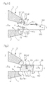
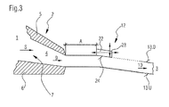
- FIGS. 1A to 1C, 2 and 3 show at least in each case a schematic and sectional side view of the downstream part of a headbox 2 of a headbox 1 for a machine for producing a merely schematically indicated fibrous web 3 from at least one pulp suspension 4.
- the fibrous web 3 formed from the at least one pulp suspension 4 may be in particular a paper, board or tissue web.
- the headbox 2 of the headbox 1 has an upper nozzle wall 5 and a lower nozzle wall 6 and two side walls, not shown, which form a nozzle chamber 7.
- the nozzle chamber 7 through which the at least one pulp suspension 3 flows narrows in the flow direction S (arrow) to form a nozzle gap 8.
- the headbox nozzle 2 carries the at least one pulp suspension 3 as a pulp suspension stream 9 (arrow) and discharges it as a pulp suspension jet 10 (arrow) via the nozzle gap 8.
- means 12 for influencing the two-sidedness of the layer orientation in the pulp suspension stream 9 (arrow) or pulp suspension jet 10 (arrow) are provided which at least impart the pulp suspension stream 9 (arrow) or pulp suspension jet 10 (arrow) at one of its two surfaces 13.O, 13.U apply to change turbulence and fluid friction.
- the surfaces 13.0, 13.U are merely exemplary of the respective pulp suspension jet 10 (arrow) indicated.
- the means 12 may be provided with a plurality of individually positionable divisions.
- the means 12 illustrated in exemplary operating settings comprise at least one positionable element 14.1, 14.2, which is arranged in the inside outlet region of a nozzle wall 5, 6 and the pulp suspension stream 9 (arrow) at least on one side.
- the positionable elements 14.1, 14.2 are arranged correspondingly on both nozzle walls 5, 6.
- the individual element 14.1, 14.2 has a substantially circular basic body 15.1, 15.2 with a nose 16.1, 16.2 pointing in the flow direction S (arrow) of the pulp suspension jet 10 (arrow), the respective nose 16.1, 16.2 preferably being tangential to the corresponding inside nozzle wall extending portion 17.1, 17.2 forms.
- the respective substantially circular basic body 15.1, 15.2 has a diameter D.1, D.2 in the range of 2 to 200 mm, preferably of 5 to 50 mm, and the preferably tangentially extending portion 17.1, 17.2 of the nose 16.1, 16.2 points a length L.1, L.2 in the range of 0 to 200 mm, preferably from 2 to 30 mm, on.
- the positioning of the respective element 14.1, 14.2 is effected by a rotation about the longitudinal axis A.1, A.2 of the associated main body 15.1, 15.2.
- Figure 1A In the execution of Figure 1A are the preferably tangentially extending portions 17.1, 17.2 of the lugs 16.1, 16.2 of the two elements 14.1, 14.2, symmetrical whereas they are in the execution of the Figure 1C also aligned in parallel. However, they can only be aligned parallel to one another.
- FIG. 1A And in the execution of Figure 1A are the preferably tangentially extending portions 17.1, 17.2 of the lugs 16.1, 16.2 of the two elements 14.1, 14.2 aligned asymmetrically and the nose 16.1 of the upper element 14.1 has a lower lip board V in the range of 0 to 50 mm, preferably from 0 to 20 mm opposite the nose 16.2 of the lower element 14.2.
- the means 12 illustrated in an exemplary operating setting comprise at least one positionable element 18.1, 18.2, which is arranged in the outlet region of a nozzle wall 5, 6 and forms the pulp suspension jet 10 (arrow) in its initial region at least on one side.
- the positionable elements 18.1, 18.2 on both nozzle walls 5, 6 are arranged accordingly.
- the individual element 18.1, 18.2 comprises a foil 19.1, 19.2, which can be wound up and unwound on a base body 20.1, 20.2 in the flow direction S (arrow) of the pulp suspension jet 10 (arrow) and for the purpose of forming an extendable flow wall 21.1, 21.2.
- the extendable flow walls 21.1, 21.2 of the two elements 18.1, 18.2 can be aligned symmetrically or asymmetrically.
- the extendable flow wall 21.1 of the upper element 18.1 has a projection Ü in the range of 0 to 400 mm, preferably 0 to 50 mm, compared to the extendable flow wall 21.2 of the lower element 18.2.
- the extendable flow wall 21.1, 21.2 of the individual element 18.1, 18.2 has a wall length W.1, W.2 in the range from 0 to 400 mm, preferably from 0 to 50 mm.
- the respective film 19.1, 19.2 has a thickness T.1, T.2 in the range from 0.1 to 5.0 mm, preferably from 0.1 to 1.0 mm.
- the individual film 19.1, 19.2 is preferably made of a flexible material, in particular a metal, a plastic or the like.
- the means 12 illustrated in an exemplary operating setting comprise at least one positionable element 22 which is arranged in the area of the pulp suspension jet 10 (arrow) and acts on it at least on one side.
- only one positionable element 22 is provided;
- the one-sided loading of the pulp suspension jet 10 (arrow) on its upper surface 13.0 by the positionable element 22 causes its at least one-sided deflection, which is shown in dashed form.
- the at least one-sided deflection will generally lead to a deflection of the entire pulp suspension jet 10 (arrow).
- the positionable element 22 comprises a brake shoe 23 with at least one active surface 24 acting on the pulp suspension jet 10 (arrow).
- the brake shoe 23 is in the height direction (H) and / or in the flow direction (S) of the pulp suspension jet 10 (arrow) by means of at least one known to the person skilled in the art Adjustable adjusting device, wherein the adjustability or positioning is indicated by means of double arrows by way of example.
- the one in the five FIGS. 1A to 1C, 2 and 3 described headbox 1 is suitable in a particular extent for carrying out the method according to the invention for influencing the two-sidedness of the layer orientation in a in a headbox of a headbox of a machine for producing an at least single-layer fibrous web, in particular a paper or board web, as a pulp suspension flow and guided by the Headbox nozzle discharged as a free jet pulp suspension jet.
- pulp suspension flow 9 or pulp suspension jet 10 (arrow) at least on one of its two surfaces 13.O, 13.U of at least one means 12 (14.1, 14.2; 18.1, 18.2; Turbulence and fluid friction is applied.
- FIGS. 1A to 1C, 2 and 3 Headbox described in a special degree for carrying out the dependent method claims.
- the invention provides a method and a headbox with which the two-sidedness of the layer orientation between the top and the bottom of the pulp suspension jet and ultimately the finished fibrous web can be influenced in a targeted manner.
Landscapes
- Paper (AREA)
Applications Claiming Priority (1)
| Application Number | Priority Date | Filing Date | Title |
|---|---|---|---|
| DE200710036945 DE102007036945A1 (de) | 2007-08-04 | 2007-08-04 | Verfahren zur Beeinflussung der Zweiseitigkeit der Layer Orientation und Stoffauflauf zur Durchführung des Verfahrens |
Publications (2)
| Publication Number | Publication Date |
|---|---|
| EP2025809A2 true EP2025809A2 (fr) | 2009-02-18 |
| EP2025809A3 EP2025809A3 (fr) | 2012-10-31 |
Family
ID=39876829
Family Applications (1)
| Application Number | Title | Priority Date | Filing Date |
|---|---|---|---|
| EP08161250A Withdrawn EP2025809A3 (fr) | 2007-08-04 | 2008-07-28 | Procédé pour influencer de la dualité de l'orientation de couche et caisse de tête destinée à l'exécution du procédé |
Country Status (2)
| Country | Link |
|---|---|
| EP (1) | EP2025809A3 (fr) |
| DE (1) | DE102007036945A1 (fr) |
Cited By (1)
| Publication number | Priority date | Publication date | Assignee | Title |
|---|---|---|---|---|
| WO2010149413A3 (fr) * | 2009-06-22 | 2011-02-24 | Voith Patent Gmbh | Caisse de tête pour une machine servant à fabriquer une bande de matériau fibreux |
Citations (1)
| Publication number | Priority date | Publication date | Assignee | Title |
|---|---|---|---|---|
| EP1452640A2 (fr) | 2003-02-27 | 2004-09-01 | Voith Paper Patent GmbH | Caisse de tête |
Family Cites Families (6)
| Publication number | Priority date | Publication date | Assignee | Title |
|---|---|---|---|---|
| FI905896A7 (fi) * | 1990-11-29 | 1992-05-30 | Valmet Paper Machinery Inc | Formningsgapsarrangemang i en dubbelviraformare av en pappersmaskin. |
| US6146501A (en) * | 1997-12-15 | 2000-11-14 | Kimberly Clark Worldwide | Cross-machine direction stiffened dividers for a papermaking headbox |
| US6117271A (en) * | 1998-04-15 | 2000-09-12 | Beloit Technologies, Inc. | Slice lip apparatus |
| AU6400399A (en) * | 1998-09-30 | 2000-04-17 | Kimberly-Clark Worldwide, Inc. | Bridge device for paper forming equipment and method |
| DE102006033847A1 (de) * | 2006-07-21 | 2008-01-24 | Voith Patent Gmbh | Stoffauflauf einer Maschine zur Herstellung einer Faserstoffbahn |
| DE102006049025A1 (de) * | 2006-10-13 | 2008-04-17 | Voith Patent Gmbh | Vorrichtung und Verfahren zur Herstellung einer Faserstoffbahn |
-
2007
- 2007-08-04 DE DE200710036945 patent/DE102007036945A1/de not_active Withdrawn
-
2008
- 2008-07-28 EP EP08161250A patent/EP2025809A3/fr not_active Withdrawn
Patent Citations (1)
| Publication number | Priority date | Publication date | Assignee | Title |
|---|---|---|---|---|
| EP1452640A2 (fr) | 2003-02-27 | 2004-09-01 | Voith Paper Patent GmbH | Caisse de tête |
Cited By (2)
| Publication number | Priority date | Publication date | Assignee | Title |
|---|---|---|---|---|
| WO2010149413A3 (fr) * | 2009-06-22 | 2011-02-24 | Voith Patent Gmbh | Caisse de tête pour une machine servant à fabriquer une bande de matériau fibreux |
| CN102428228A (zh) * | 2009-06-22 | 2012-04-25 | 福伊特专利公司 | 用于制造纤维材料幅的机器所用的流浆箱 |
Also Published As
| Publication number | Publication date |
|---|---|
| EP2025809A3 (fr) | 2012-10-31 |
| DE102007036945A1 (de) | 2009-02-05 |
Similar Documents
| Publication | Publication Date | Title |
|---|---|---|
| EP0711869B1 (fr) | Caisse de tête à plusieurs couches | |
| EP2379801B1 (fr) | Système de mise en bande destiné à une machine de production d'une bande de matière fibreuse multicouche | |
| DE69707256T2 (de) | DOPPELSIEBFORMER MIT ROLLE UND KLINGE FüR EINE PAPIERMASCHINE | |
| EP0581051B1 (fr) | Caisse de tête à plusieurs couches pour une machine à papier ou analogue | |
| EP2739780B1 (fr) | Système de formation de feuille pour une machine de fabrication d'une bande de matière fibreuse à deux couches ou plus | |
| WO2010046312A2 (fr) | Caisse de tête bicouches pour une machine de fabrication d'une bande bicouches de matière fibreuse | |
| DE2716598A1 (de) | Doppelsiebteil einer papiermaschine | |
| EP2446083B1 (fr) | Tête de caisse pour une machine servant à fabriquer une bande de matériau fibreux | |
| EP1881106B1 (fr) | Caisse de tête d'une machine destinée à la fabrication d'une bande de matière fibreuse | |
| DE69810980T2 (de) | Doppelsiebformer in einer Papiermaschine mit einer Entwässerungsvorrichtung | |
| DE102007036945A1 (de) | Verfahren zur Beeinflussung der Zweiseitigkeit der Layer Orientation und Stoffauflauf zur Durchführung des Verfahrens | |
| EP0899376B1 (fr) | Section de formage avec chariot de format | |
| DE2626262A1 (de) | Zweisiebformer in einer papiermaschine | |
| EP4328376B1 (fr) | Formeur à tamis oblique | |
| EP2085511B1 (fr) | Caisse de tête multicouche pour une machine destinée à la fabrication d'une bande de matière fibreuse multicouche | |
| EP1659211B1 (fr) | Système de formation d'une machine pour fabriquer une bande fibreuse | |
| DE102010041332A1 (de) | Blattbildungssystem | |
| EP2205792B1 (fr) | Formeur à double toile | |
| EP2072677B1 (fr) | Partie humide à deux toiles pour une machine destinée à la fabrication d'une bande de matière fibreuse à partir d'au moins une suspension de matière fibreuse | |
| EP1953296A1 (fr) | Procédé de fabrication d'une bande de matière fibreuse et section de formage à deux toiles pour la mise en oeuvre du procédé | |
| DE102005010628A1 (de) | Stoffauflauf | |
| DE10245156A1 (de) | Stoffauflauf | |
| DE102007035488A1 (de) | Verfahren zur Herstellung einer Faserstoffbahn und Doppelsiebformer zur Durchführung des Verfahrens | |
| DE10318035A1 (de) | Stoffauflauf | |
| DE10256510A1 (de) | Stoffauflauf einer Papier- oder Kartonmaschine zur Herstellung einer Faserstoffbahn |
Legal Events
| Date | Code | Title | Description |
|---|---|---|---|
| PUAI | Public reference made under article 153(3) epc to a published international application that has entered the european phase |
Free format text: ORIGINAL CODE: 0009012 |
|
| AK | Designated contracting states |
Kind code of ref document: A2 Designated state(s): AT BE BG CH CY CZ DE DK EE ES FI FR GB GR HR HU IE IS IT LI LT LU LV MC MT NL NO PL PT RO SE SI SK TR |
|
| AX | Request for extension of the european patent |
Extension state: AL BA MK RS |
|
| PUAL | Search report despatched |
Free format text: ORIGINAL CODE: 0009013 |
|
| AK | Designated contracting states |
Kind code of ref document: A3 Designated state(s): AT BE BG CH CY CZ DE DK EE ES FI FR GB GR HR HU IE IS IT LI LT LU LV MC MT NL NO PL PT RO SE SI SK TR |
|
| AX | Request for extension of the european patent |
Extension state: AL BA MK RS |
|
| RIC1 | Information provided on ipc code assigned before grant |
Ipc: D21F 1/02 20060101AFI20120921BHEP |
|
| AKY | No designation fees paid | ||
| REG | Reference to a national code |
Ref country code: DE Ref legal event code: R108 |
|
| REG | Reference to a national code |
Ref country code: DE Ref legal event code: R108 Effective date: 20130703 |
|
| STAA | Information on the status of an ep patent application or granted ep patent |
Free format text: STATUS: THE APPLICATION IS DEEMED TO BE WITHDRAWN |
|
| 18D | Application deemed to be withdrawn |
Effective date: 20130503 |