EP2025843B1 - Fenêtre ou porte et composition d'un verrou pour une fenêtre ou une porte - Google Patents
Fenêtre ou porte et composition d'un verrou pour une fenêtre ou une porte Download PDFInfo
- Publication number
- EP2025843B1 EP2025843B1 EP08104496A EP08104496A EP2025843B1 EP 2025843 B1 EP2025843 B1 EP 2025843B1 EP 08104496 A EP08104496 A EP 08104496A EP 08104496 A EP08104496 A EP 08104496A EP 2025843 B1 EP2025843 B1 EP 2025843B1
- Authority
- EP
- European Patent Office
- Prior art keywords
- locking
- roller
- window
- main body
- leaf
- Prior art date
- Legal status (The legal status is an assumption and is not a legal conclusion. Google has not performed a legal analysis and makes no representation as to the accuracy of the status listed.)
- Active
Links
Images


Classifications
-
- E—FIXED CONSTRUCTIONS
- E05—LOCKS; KEYS; WINDOW OR DOOR FITTINGS; SAFES
- E05C—BOLTS OR FASTENING DEVICES FOR WINGS, SPECIALLY FOR DOORS OR WINDOWS
- E05C9/00—Arrangements of simultaneously actuated bolts or other securing devices at well-separated positions on the same wing
- E05C9/18—Details of fastening means or of fixed retaining means for the ends of bars
- E05C9/1808—Keepers
-
- E—FIXED CONSTRUCTIONS
- E05—LOCKS; KEYS; WINDOW OR DOOR FITTINGS; SAFES
- E05D—HINGES OR SUSPENSION DEVICES FOR DOORS, WINDOWS OR WINGS
- E05D15/00—Suspension arrangements for wings
- E05D15/48—Suspension arrangements for wings allowing alternative movements
- E05D15/52—Suspension arrangements for wings allowing alternative movements for opening about a vertical as well as a horizontal axis
- E05D15/526—Safety devices
-
- E—FIXED CONSTRUCTIONS
- E05—LOCKS; KEYS; WINDOW OR DOOR FITTINGS; SAFES
- E05F—DEVICES FOR MOVING WINGS INTO OPEN OR CLOSED POSITION; CHECKS FOR WINGS; WING FITTINGS NOT OTHERWISE PROVIDED FOR, CONCERNED WITH THE FUNCTIONING OF THE WING
- E05F7/00—Accessories for wings not provided for in other groups of this subclass
- E05F7/06—Devices for taking the weight of the wing, arranged away from the hinge axis
-
- E—FIXED CONSTRUCTIONS
- E05—LOCKS; KEYS; WINDOW OR DOOR FITTINGS; SAFES
- E05Y—INDEXING SCHEME ASSOCIATED WITH SUBCLASSES E05D AND E05F, RELATING TO CONSTRUCTION ELEMENTS, ELECTRIC CONTROL, POWER SUPPLY, POWER SIGNAL OR TRANSMISSION, USER INTERFACES, MOUNTING OR COUPLING, DETAILS, ACCESSORIES, AUXILIARY OPERATIONS NOT OTHERWISE PROVIDED FOR, APPLICATION THEREOF
- E05Y2900/00—Application of doors, windows, wings or fittings thereof
- E05Y2900/10—Application of doors, windows, wings or fittings thereof for buildings or parts thereof
- E05Y2900/13—Type of wing
- E05Y2900/132—Doors
-
- E—FIXED CONSTRUCTIONS
- E05—LOCKS; KEYS; WINDOW OR DOOR FITTINGS; SAFES
- E05Y—INDEXING SCHEME ASSOCIATED WITH SUBCLASSES E05D AND E05F, RELATING TO CONSTRUCTION ELEMENTS, ELECTRIC CONTROL, POWER SUPPLY, POWER SIGNAL OR TRANSMISSION, USER INTERFACES, MOUNTING OR COUPLING, DETAILS, ACCESSORIES, AUXILIARY OPERATIONS NOT OTHERWISE PROVIDED FOR, APPLICATION THEREOF
- E05Y2900/00—Application of doors, windows, wings or fittings thereof
- E05Y2900/10—Application of doors, windows, wings or fittings thereof for buildings or parts thereof
- E05Y2900/13—Type of wing
- E05Y2900/148—Windows
Definitions
- the invention relates to a window or a door according to the preamble of claim 1.
- the invention also relates to a component set for a window or a door.
- a latch part in which a U-shaped latch plate is associated with a base body.
- the latch plate has a latch slot for engaging a via a drive rod fitting longitudinally displaceable locking element with mushroom shape.
- the locking slot is adapted to the tapered shaft and the head of the locking element so that the shaft can enter laterally into the slot, but the head is dimensioned larger than the inside width of the slot. As a result, the locking element can not be led out of the locking slot perpendicular to the folding plane.
- the body is used in addition to the adaptation to different profiles of the spar of the window or the door and the support of the locking element, the shaft of which remains spaced from the longitudinal edges of the locking slot.
- different base bodies matched to the dimensions of the profile, are coupled with identical locking plates. The coupling is done by clipping, the assembly of the latch parts is done by means of fastening screws, which penetrate both the latch plate and the base body.
- a latch member is known in which the side of a latch plate next to a ramp is attached to which a mounted on the wing role in the leading of the wing is supported on the frame.
- Bearing block and roller are used for relative alignment of the wing to the frame to a terminals of the relative to the frame, if necessary after a time lapse and wear of the hinges moved wing to achieve.
- roller casserole or wing lifter designated facilities are from the AT-PS 286820 , of the DE-PS 336544 , and the German utility model 1813011 known.
- From the FR 1012426 of the DE-GM 1978136 and the DE 29511379 U1 Embodiments are known in which the rollers are fixedly mounted on the frame.
- the invention is therefore based on the object to remedy these disadvantages.
- a universal handling of the latch part should be achieved.
- the invention provides that the base body has a receptacle for at least one roller, and the role of the wing is assigned a casserole.
- This standardization of the Riegeteils and a wing lifter is achieved in each of which a single body can be used.
- the support in the region of the latch part is advantageous since the space between the wing and the frame free space is severely limited by the latch member itself and therefore it can come especially in this area to a terminals.
- the at least one component less must be mounted because the roller casserole or the wing lifter and the closing part are combined into one component.
- roller is associated with an opening in the latch plate, which covers the receptacle at least partially, so that the role can protrude through the latch plate, without the mechanical stability of the latch plate is reduced by an extended opening area.
- the role is determined by the latch plate on the base body, since the latch plate covers the receptacle at least partially.
- the receptacle for the roll consists of a pocket which is open approximately perpendicular to the fold.
- a simple storage of the role is achieved.
- the applied through the wing load is introduced into the body and can be optimally absorbed by the closed in the loading direction pocket.
- the base body is a symmetrical shaped body relative to its longitudinal axis, the base body can be used universally.
- roller is a roller having longitudinally identical bearing journals.
- latch member has two latch slots, then there is uniform use in right and left opening windows.
- the universal handling of the latch member is particularly effected by a component set according to claim 7.
- the latch member can be used by optional use of a base body without roller and a closed latch plate as the exclusive latch part.
- the latch part contains no openings that can absorb dirt or interfere with the cleaning of the window.
- Of the Base can be equipped with an additional wing lifter by adding a roller and using a latch plate having a corresponding opening for the roller.
- the production of the base body to be adapted to the profiling of the frame can be done more cost-effectively by a higher number of pieces and there are no new tooling and handling costs due to a further base body.
- Such a component set can be used universally in that at least one latch plate is intended for engagement of a locking element causing the tilt lock.
- the base body is a symmetrical shaped body relative to the longitudinal center axis, at least the base body can be used for windows opening to the right and to the left.
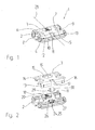
- latch member is a main body with 2 and a latch plate 3.
- the locking plate 3 has two opposite locking slots 4, 5 and two holes 6, 7.
- the locking slots 4, 5 are used for engagement of locking elements, as will be shown below.
- the holes 6, 7 serve to pass through fastening screws, with which the latch part 1 can be fixed to a frame rail of a window.
- the holes 6, 7 are with Countersinks for receiving the screw head provided.
- the latch part 1 is screwed to the fold of the frame, wherein the base body 2 is adapted to the underside of a profiling of the fold.
- the base body 2 has clearances 8, 9 in the region of the locking slots 4, 5, so that a locking element entering into the locking slots 4, 5 has sufficient free space.
- a roller 11 is attached near a front edge 10 of the latch part 1.
- the roller 11 is arranged so that its circumference projects beyond an approximately parallel to the fold extending surface 12 of the latch plate 3 and also projects beyond a radius 13.
- the edge 10 of the latch part 1 is located in the opening direction of the wing, so that it is associated with an approach to the frame, when closing the wing, the wing first.
- the latch plate 3 is formed as an L-shaped plate.
- the leg 14 includes the holes 6, 7 and an opening 15. At the approximately perpendicular to the leg 14 perpendicular leg 16 is an open-edged opening 17 is attached, which serves to pass through the roller 11.
- the latch plate 3 can be produced by stamping bending from a thin metal sheet by this configuration.
- the opening 15 can be assigned to a latching device 18 of the main body 2.
- the edge 19 of the opening 15 is thereby overlapped by a detent 20, which is designed as a latching tooth and with respect to a survey 21 is elastically deformable.
- the main body 2 engages over the locking plate 3 along the front edge 10.
- a receptacle 24 for the roller 11 is provided in the main body 2. This has an approximately perpendicular to the surface 12 and thus also perpendicular to the fold of the frame aligned open pocket 25 to which two storage pockets 26, 27 connect, which are transverse to the longitudinal central axis 28 (FIG. Fig. 1 ).
- the roller 11 is formed as a roller, the coaxial identical bearing pins 29, 30 beivi that the bearing pockets 26, 27 can be assigned. While the pocket 25 corresponds in its position and dimension approximately to the opening 17, the bearing pockets 26, 27 are covered by the locking plate 3, so that the roller 11 is fixed by the locking plate 3 on the base body 2.
- the latch plate 3 with the opening 17 provides an axial fixation in that the opening 17 engages around the roller 11 fork-shaped. An axial fixation in the body is thus unnecessary.
- the base body 2 relative to its longitudinal central axis 28 is a symmetrical molded body, which can be inexpensively made of plastic.
- the loads of the blade acting on the roller 11 can be received positively on the exclusively upward, in the direction of the wing, open trough-like bearing pockets 26, 27.
- the latch part 1 can be used both with the window opening to the right and to the left.
- a latch part 1 'visible which is also composed of a base body 2 and a latch plate 3'.
- the locking plate 3 ' but without the opening 17 ( Fig. 2 ) carried out, so that in addition to the bearing pockets 26, 27 and the bag 25 is covered.
- the latch part 1 ' is designed as a latch part without the roller casserole.
- a corresponding component set for a latch part 1 with roller casserole and a latch part 1 'without roller casserole is therefore always based on a uniform base body 2, which advantageously still has a relation to its longitudinal central axis 28 (FIG. Fig. 1 ) is designed symmetrically.
- the locking plates 3, 3 ' are of identical construction with respect to the coupling elements 18, 19, 20 cooperating with the base body 2 and differ only in that the first locking plate 1 has the opening 17 for the passage of the roller 11, while a second locking plate 3' the installation space of the roller 11, so the bag 25, the base body 2 covers when no roller 11 is attached.
- the thus configured latch member 1 can be converted by use of another latch plate 3 'in an ordinary latch part 1' or vice versa. This can also be done later, without the bolt part 1 or 1 'has to be realigned to the frame itself. It can be done according to the Fig. 5 be provided that at least the locking plate 3 or 3 'for engaging a tilt locking of the window causing locking element 31 is determined.
- the locking element 31 is mounted in the embodiment on a corner drive 32, which is part of a drive rod fitting of the window.
- the tilt lock is according to the EP 0 628 691 B2 to which reference is made in full.
- a second locking element 33 is provided, which is also designed as a mushroom pin.
- the locking elements 31, 33 depart from the in the Fig. 5 illustrated opening position of the espagnolette fitting mutually in the locking slots 4, 5, wherein the locking element 31 due to the slimmer shaft allows an inclination of the wing relative to the frame. From the Fig. 5 can still be seen that on the faceplate 34 of the corner 32 a casserole 35 is mounted, which cooperates with the roller 11.
- the casserole 35 is attached to the corner drive 32 and the wing via a fastening screw, which must be installed anyway.
- the assembly therefore represents only a small overhead.
- already assembled latch parts 1 'can be converted into latch parts 1. It can also be provided that a plurality of latch parts 1 are provided on the lower horizontal frame edge.
Landscapes
- Engineering & Computer Science (AREA)
- Mechanical Engineering (AREA)
- Support Devices For Sliding Doors (AREA)
- Lock And Its Accessories (AREA)
- Window Of Vehicle (AREA)
- Extensible Doors And Revolving Doors (AREA)
- Wing Frames And Configurations (AREA)
Claims (9)
- Fenêtre ou porte, qui est dotée d'une pièce de verrouillage (1, 1'), en particulier d'un dispositif de blocage en basculement, qui est disposée dans la feuillure, entre le battant et le cadre dormant, et d'une ferrure à crémone (32), agencée sur le battant, et d'au moins un élément de verrouillage (31, 33), qui peut être mû par l'intermédiaire de la ferrure à crémone (32) et auquel est associé la pièce de verrouillage (1, 1'), sur le cadre dormant, sachant que le battant peut être amené, par l'intermédiaire de la ferrure à crémone (32), au moins d'une position de fermeture à au moins une position d'ouverture, dans laquelle ledit battant peut être pivoté hors du cadre dormant, la pièce de verrouillage (1, 1') consistant au moins en un corps de base (2) et une plaque de verrouillage (3, 3'), qui peut être couplée avec celui-ci, caractérisée en ce que le corps de base (2) est pourvu d'un réceptacle (24) pour au moins un rouleau (11) et qu'une surface de roulement (35) peut être associée au rouleau (11), sur le battant.
- Fenêtre ou porte selon la revendication 1, caractérisée en ce qu'au rouleau (11) est associée une ouverture (17), pratiquée dans la plaque de verrouillage (3), qui recouvre au moins partiellement le réceptacle (24).
- Fenêtre ou porte selon revendication 1 ou 2, caractérisée en ce que le réceptacle (24), prévu pour le rouleau (11), consiste en une poche (25), qui est ouverte à peu près perpendiculairement à la feuillure.
- Fenêtre ou porte selon l'une des revendications 1 à 3, caractérisée en ce que le corps de base (2) est un corps moulé, symétrique par rapport à son axe central, longitudinal (28).
- Fenêtre ou porte selon l'une des revendications 1 à 4, caractérisée en ce que le rouleau (11) est un cylindre, qui est doté de bouts d'arbre (29, 30) identiques, orientés dans la direction longitudinale.
- Fenêtre ou porte selon l'une des revendications 1 à 5, caractérisée en ce que la pièce de verrouillage (1, 1') est dotée de deux fentes de verrouillage (4, 5).
- Jeu de composants pour des pièces de verrouillage (1, 1'), en particulier pour une fenêtre ou une porte selon la revendication 1, avec une ferrure à crémone, dotée d'éléments de verrouillage (31, 33) déplaçables, qui consiste en un corps de base (2) et au moins deux plaques de verrouillage (3, 3'), qui peuvent être couplées, alternativement, avec celui-ci, sachant que le corps de base (2) est doté d'au moins un réceptacle (24) pour au moins un rouleau (11), auquel est associé, sur le battant, une surface de roulement(35), sachant que les plaques de verrouillage (3, 3') sont de conception identique, au moins en ce qui concerne les organes de couplage (18, 19, 20), qui coopèrent avec le corps de base (2), et qu'une première plaque de verrouillage (3) est dotée d'une ouverture (17) pour le passage du rouleau (11), tandis qu'une deuxième plaque de verrouillage (3') recouvre le logement du rouleau (11), pratiqueé dans le corps de base (2), quand aucun rouleau (11) n'est installé.
- Jeu de composants selon la revendication 7, caractérisé en ce qu'au moins une plaque de verrouillage (3, 3') est destinée à entrer en prise avec un élément de verrouillage (31), pour la réalisation d'un verrouillage par blocage en basculement.
- Jeu de composants selon revendication 7 ou 8, caractérisé en ce que le corps de base (2) est un corps moulé, symétrique par rapport à l'axe central, longitudinal (28).
Priority Applications (1)
| Application Number | Priority Date | Filing Date | Title |
|---|---|---|---|
| PL08104496T PL2025843T3 (pl) | 2007-08-14 | 2008-06-20 | Okno lub drzwi i zestaw części rygla dla okna lub drzwi |
Applications Claiming Priority (1)
| Application Number | Priority Date | Filing Date | Title |
|---|---|---|---|
| DE202007011394U DE202007011394U1 (de) | 2007-08-14 | 2007-08-14 | Fenster oder Tür und Bauteilsatz eines Riegelteils für ein Fenster oder eine Tür |
Publications (3)
| Publication Number | Publication Date |
|---|---|
| EP2025843A2 EP2025843A2 (fr) | 2009-02-18 |
| EP2025843A3 EP2025843A3 (fr) | 2010-08-04 |
| EP2025843B1 true EP2025843B1 (fr) | 2011-11-30 |
Family
ID=39846576
Family Applications (1)
| Application Number | Title | Priority Date | Filing Date |
|---|---|---|---|
| EP08104496A Active EP2025843B1 (fr) | 2007-08-14 | 2008-06-20 | Fenêtre ou porte et composition d'un verrou pour une fenêtre ou une porte |
Country Status (4)
| Country | Link |
|---|---|
| EP (1) | EP2025843B1 (fr) |
| AT (1) | ATE535670T1 (fr) |
| DE (1) | DE202007011394U1 (fr) |
| PL (1) | PL2025843T3 (fr) |
Cited By (1)
| Publication number | Priority date | Publication date | Assignee | Title |
|---|---|---|---|---|
| DE202019106095U1 (de) | 2019-11-04 | 2019-11-15 | Siegenia-Aubi Kg | Bauteilsystem für einen Riegeleingriff |
Families Citing this family (1)
| Publication number | Priority date | Publication date | Assignee | Title |
|---|---|---|---|---|
| DE102015215458B3 (de) * | 2015-08-13 | 2016-12-22 | Roto Frank Ag | Beschlagteil mit schräg zur Schließrichtung eines Fensters oder einer Tür angeordneter Walze sowie ein Fenster oder eine Tür mit einem solchen Beschlagteil |
Family Cites Families (10)
| Publication number | Priority date | Publication date | Assignee | Title |
|---|---|---|---|---|
| DE336544C (de) | 1921-05-09 | Edouard Debant | Vorrichtung zum Heben von Tueren mittels Laufrolle und Auflaufbahn | |
| FR1012426A (fr) | 1949-08-26 | 1952-07-09 | Dispositif destiné à empêcher le coincement et le frottement des battants de fenêtres, ou autres, dans leurs encadrements | |
| DE1813011U (de) | 1960-03-28 | 1960-06-09 | Hartmann & Co W | Vorrichtung zum wahlweisen drehen und kippen von metallfenstern. |
| DE1978136U (de) | 1967-07-18 | 1968-02-01 | Eugen Notter O H G | Fenster mit stockrahmen und fluegelrahmen. |
| AT286820B (de) | 1967-11-30 | 1970-12-28 | Ver Baubeschlag Gretsch Co | Einstellbare Auflaufvorrichtung zum Anheben der sich beim Öffnen senkenden Flügel von Fenstern, Türen od.dgl. in eine vorbestimmte Schließstellung |
| DE1813011A1 (de) | 1968-12-06 | 1970-07-09 | Basf Ag | Photopolymerisierbare Stoffmischungen |
| DE9308472U1 (de) | 1993-06-07 | 1993-09-02 | Pax Schweikhard GmbH, 55218 Ingelheim | Dreh-Kipp-Beschlag für Fenster, Türen o.dgl. |
| DE29511379U1 (de) | 1995-07-14 | 1996-11-14 | Niemann, Hans Dieter, 50169 Kerpen | Auflaufbock |
| DE29914072U1 (de) | 1999-08-16 | 1999-11-18 | Siegenia-Frank Kg, 57074 Siegen | Verriegelungsbeschlag |
| DE10009288A1 (de) | 2000-02-28 | 2001-08-30 | Siegenia Frank Kg | Auflaufbock |
-
2007
- 2007-08-14 DE DE202007011394U patent/DE202007011394U1/de not_active Expired - Lifetime
-
2008
- 2008-06-20 AT AT08104496T patent/ATE535670T1/de active
- 2008-06-20 EP EP08104496A patent/EP2025843B1/fr active Active
- 2008-06-20 PL PL08104496T patent/PL2025843T3/pl unknown
Cited By (2)
| Publication number | Priority date | Publication date | Assignee | Title |
|---|---|---|---|---|
| DE202019106095U1 (de) | 2019-11-04 | 2019-11-15 | Siegenia-Aubi Kg | Bauteilsystem für einen Riegeleingriff |
| EP3816375A1 (fr) | 2019-11-04 | 2021-05-05 | Siegenia-Aubi Kg | Système de composants pour l'enclenchement d'un verrou |
Also Published As
| Publication number | Publication date |
|---|---|
| ATE535670T1 (de) | 2011-12-15 |
| EP2025843A3 (fr) | 2010-08-04 |
| PL2025843T3 (pl) | 2012-04-30 |
| DE202007011394U1 (de) | 2008-12-24 |
| EP2025843A2 (fr) | 2009-02-18 |
Similar Documents
| Publication | Publication Date | Title |
|---|---|---|
| EP2085553B1 (fr) | Ferrure pour palier d'angle | |
| EP3102759B1 (fr) | Ferrure d'un battant de fenêtres ou de portes, au moins relevable et coulissant | |
| EP3060737B1 (fr) | Fenêtre ou porte équipée d'une ferrure | |
| EP1568833B1 (fr) | Gâche pour une fenêtre ou une porte | |
| EP2251508B1 (fr) | Gâche pour fenêtres ou portes | |
| EP2025843B1 (fr) | Fenêtre ou porte et composition d'un verrou pour une fenêtre ou une porte | |
| DE3904210C2 (fr) | ||
| DE3619682C2 (fr) | ||
| DE19911893C2 (de) | Beschlaganordnung | |
| EP1580374B1 (fr) | Fenêtre ou porte | |
| DE10056607C1 (de) | Fehlbedienungssperre für Treibstangenbeschläge | |
| EP1498563B1 (fr) | Dispositif pour créer une fente d'aération | |
| EP1425489B1 (fr) | Ferrure oscillobattante | |
| EP2122092B1 (fr) | Ferrure | |
| EP3371397A1 (fr) | Ensemble ferrure | |
| EP0246431A2 (fr) | Dispositif déflecteur pour panneau basculant, en particulier panneau oscillo-battant ou battant coulissant et basculant, de fenêtres, portes ou similaires | |
| EP3350394B1 (fr) | Ferrure du type crémone | |
| EP0887501A2 (fr) | Ferrure arrangée en feuillure pour fenêtre, porte ou similaire | |
| EP1582672B1 (fr) | Renvoi d'angle pour ventilation réglable et limitation d'ouverture dans une condamnation centrale | |
| EP2090730B1 (fr) | Dispositif de verrouillage | |
| EP4685318A1 (fr) | Ferrure avec un pêne auxiliaire, en particulier pour fenêtres ou portes à deux vantaux sans montant central | |
| DE7713995U1 (de) | Eckumlenkung fuer einen stellstangenbeschlag eines drehkippfensters o.dgl. | |
| DE10009288A1 (de) | Auflaufbock | |
| DE202018000955U1 (de) | Beschlagteil für ein Fenster oder eine Tür | |
| EP2154318A1 (fr) | Fenêtre ou porte avec limiteur d'ouverture |
Legal Events
| Date | Code | Title | Description |
|---|---|---|---|
| PUAI | Public reference made under article 153(3) epc to a published international application that has entered the european phase |
Free format text: ORIGINAL CODE: 0009012 |
|
| AK | Designated contracting states |
Kind code of ref document: A2 Designated state(s): AT BE BG CH CY CZ DE DK EE ES FI FR GB GR HR HU IE IS IT LI LT LU LV MC MT NL NO PL PT RO SE SI SK TR |
|
| AX | Request for extension of the european patent |
Extension state: AL BA MK RS |
|
| PUAL | Search report despatched |
Free format text: ORIGINAL CODE: 0009013 |
|
| AK | Designated contracting states |
Kind code of ref document: A3 Designated state(s): AT BE BG CH CY CZ DE DK EE ES FI FR GB GR HR HU IE IS IT LI LT LU LV MC MT NL NO PL PT RO SE SI SK TR |
|
| AX | Request for extension of the european patent |
Extension state: AL BA MK RS |
|
| RIC1 | Information provided on ipc code assigned before grant |
Ipc: E05F 7/06 20060101ALI20100628BHEP Ipc: E05C 9/18 20060101AFI20100628BHEP |
|
| 17P | Request for examination filed |
Effective date: 20100818 |
|
| AKX | Designation fees paid |
Designated state(s): AT BE BG CH CY CZ DE DK EE ES FI FR GB GR HR HU IE IS IT LI LT LU LV MC MT NL NO PL PT RO SE SI SK TR |
|
| REG | Reference to a national code |
Ref country code: DE Ref legal event code: R079 Ref document number: 502008005727 Country of ref document: DE Free format text: PREVIOUS MAIN CLASS: E05C0009000000 Ipc: E05C0009180000 |
|
| GRAP | Despatch of communication of intention to grant a patent |
Free format text: ORIGINAL CODE: EPIDOSNIGR1 |
|
| RIC1 | Information provided on ipc code assigned before grant |
Ipc: E05F 7/06 20060101ALI20110714BHEP Ipc: E05C 9/18 20060101AFI20110714BHEP |
|
| GRAS | Grant fee paid |
Free format text: ORIGINAL CODE: EPIDOSNIGR3 |
|
| GRAA | (expected) grant |
Free format text: ORIGINAL CODE: 0009210 |
|
| AK | Designated contracting states |
Kind code of ref document: B1 Designated state(s): AT BE BG CH CY CZ DE DK EE ES FI FR GB GR HR HU IE IS IT LI LT LU LV MC MT NL NO PL PT RO SE SI SK TR |
|
| REG | Reference to a national code |
Ref country code: GB Ref legal event code: FG4D Free format text: NOT ENGLISH Ref country code: CH Ref legal event code: EP |
|
| REG | Reference to a national code |
Ref country code: IE Ref legal event code: FG4D Free format text: LANGUAGE OF EP DOCUMENT: GERMAN |
|
| REG | Reference to a national code |
Ref country code: DE Ref legal event code: R096 Ref document number: 502008005727 Country of ref document: DE Effective date: 20120216 |
|
| REG | Reference to a national code |
Ref country code: NL Ref legal event code: VDEP Effective date: 20111130 |
|
| LTIE | Lt: invalidation of european patent or patent extension |
Effective date: 20111130 |
|
| PG25 | Lapsed in a contracting state [announced via postgrant information from national office to epo] |
Ref country code: IS Free format text: LAPSE BECAUSE OF FAILURE TO SUBMIT A TRANSLATION OF THE DESCRIPTION OR TO PAY THE FEE WITHIN THE PRESCRIBED TIME-LIMIT Effective date: 20120330 Ref country code: LT Free format text: LAPSE BECAUSE OF FAILURE TO SUBMIT A TRANSLATION OF THE DESCRIPTION OR TO PAY THE FEE WITHIN THE PRESCRIBED TIME-LIMIT Effective date: 20111130 Ref country code: NO Free format text: LAPSE BECAUSE OF FAILURE TO SUBMIT A TRANSLATION OF THE DESCRIPTION OR TO PAY THE FEE WITHIN THE PRESCRIBED TIME-LIMIT Effective date: 20120229 |
|
| REG | Reference to a national code |
Ref country code: PL Ref legal event code: T3 |
|
| PG25 | Lapsed in a contracting state [announced via postgrant information from national office to epo] |
Ref country code: HR Free format text: LAPSE BECAUSE OF FAILURE TO SUBMIT A TRANSLATION OF THE DESCRIPTION OR TO PAY THE FEE WITHIN THE PRESCRIBED TIME-LIMIT Effective date: 20111130 Ref country code: NL Free format text: LAPSE BECAUSE OF FAILURE TO SUBMIT A TRANSLATION OF THE DESCRIPTION OR TO PAY THE FEE WITHIN THE PRESCRIBED TIME-LIMIT Effective date: 20111130 Ref country code: LV Free format text: LAPSE BECAUSE OF FAILURE TO SUBMIT A TRANSLATION OF THE DESCRIPTION OR TO PAY THE FEE WITHIN THE PRESCRIBED TIME-LIMIT Effective date: 20111130 Ref country code: SI Free format text: LAPSE BECAUSE OF FAILURE TO SUBMIT A TRANSLATION OF THE DESCRIPTION OR TO PAY THE FEE WITHIN THE PRESCRIBED TIME-LIMIT Effective date: 20111130 Ref country code: SE Free format text: LAPSE BECAUSE OF FAILURE TO SUBMIT A TRANSLATION OF THE DESCRIPTION OR TO PAY THE FEE WITHIN THE PRESCRIBED TIME-LIMIT Effective date: 20111130 Ref country code: PT Free format text: LAPSE BECAUSE OF FAILURE TO SUBMIT A TRANSLATION OF THE DESCRIPTION OR TO PAY THE FEE WITHIN THE PRESCRIBED TIME-LIMIT Effective date: 20120330 |
|
| REG | Reference to a national code |
Ref country code: IE Ref legal event code: FD4D |
|
| PG25 | Lapsed in a contracting state [announced via postgrant information from national office to epo] |
Ref country code: CY Free format text: LAPSE BECAUSE OF FAILURE TO SUBMIT A TRANSLATION OF THE DESCRIPTION OR TO PAY THE FEE WITHIN THE PRESCRIBED TIME-LIMIT Effective date: 20111130 |
|
| PG25 | Lapsed in a contracting state [announced via postgrant information from national office to epo] |
Ref country code: BG Free format text: LAPSE BECAUSE OF FAILURE TO SUBMIT A TRANSLATION OF THE DESCRIPTION OR TO PAY THE FEE WITHIN THE PRESCRIBED TIME-LIMIT Effective date: 20120229 Ref country code: DK Free format text: LAPSE BECAUSE OF FAILURE TO SUBMIT A TRANSLATION OF THE DESCRIPTION OR TO PAY THE FEE WITHIN THE PRESCRIBED TIME-LIMIT Effective date: 20111130 Ref country code: EE Free format text: LAPSE BECAUSE OF FAILURE TO SUBMIT A TRANSLATION OF THE DESCRIPTION OR TO PAY THE FEE WITHIN THE PRESCRIBED TIME-LIMIT Effective date: 20111130 Ref country code: IE Free format text: LAPSE BECAUSE OF FAILURE TO SUBMIT A TRANSLATION OF THE DESCRIPTION OR TO PAY THE FEE WITHIN THE PRESCRIBED TIME-LIMIT Effective date: 20111130 Ref country code: CZ Free format text: LAPSE BECAUSE OF FAILURE TO SUBMIT A TRANSLATION OF THE DESCRIPTION OR TO PAY THE FEE WITHIN THE PRESCRIBED TIME-LIMIT Effective date: 20111130 Ref country code: SK Free format text: LAPSE BECAUSE OF FAILURE TO SUBMIT A TRANSLATION OF THE DESCRIPTION OR TO PAY THE FEE WITHIN THE PRESCRIBED TIME-LIMIT Effective date: 20111130 |
|
| PG25 | Lapsed in a contracting state [announced via postgrant information from national office to epo] |
Ref country code: RO Free format text: LAPSE BECAUSE OF FAILURE TO SUBMIT A TRANSLATION OF THE DESCRIPTION OR TO PAY THE FEE WITHIN THE PRESCRIBED TIME-LIMIT Effective date: 20111130 |
|
| PLBE | No opposition filed within time limit |
Free format text: ORIGINAL CODE: 0009261 |
|
| STAA | Information on the status of an ep patent application or granted ep patent |
Free format text: STATUS: NO OPPOSITION FILED WITHIN TIME LIMIT |
|
| 26N | No opposition filed |
Effective date: 20120831 |
|
| REG | Reference to a national code |
Ref country code: DE Ref legal event code: R097 Ref document number: 502008005727 Country of ref document: DE Effective date: 20120831 |
|
| BERE | Be: lapsed |
Owner name: SIEGENIA-AUBI K.G. Effective date: 20120630 |
|
| PG25 | Lapsed in a contracting state [announced via postgrant information from national office to epo] |
Ref country code: MC Free format text: LAPSE BECAUSE OF NON-PAYMENT OF DUE FEES Effective date: 20120630 |
|
| REG | Reference to a national code |
Ref country code: CH Ref legal event code: PL |
|
| REG | Reference to a national code |
Ref country code: CH Ref legal event code: PL |
|
| GBPC | Gb: european patent ceased through non-payment of renewal fee |
Effective date: 20120620 |
|
| REG | Reference to a national code |
Ref country code: HU Ref legal event code: AG4A Ref document number: E015003 Country of ref document: HU |
|
| PG25 | Lapsed in a contracting state [announced via postgrant information from national office to epo] |
Ref country code: CH Free format text: LAPSE BECAUSE OF NON-PAYMENT OF DUE FEES Effective date: 20120630 Ref country code: GB Free format text: LAPSE BECAUSE OF NON-PAYMENT OF DUE FEES Effective date: 20120620 Ref country code: BE Free format text: LAPSE BECAUSE OF NON-PAYMENT OF DUE FEES Effective date: 20120630 Ref country code: LI Free format text: LAPSE BECAUSE OF NON-PAYMENT OF DUE FEES Effective date: 20120630 |
|
| PG25 | Lapsed in a contracting state [announced via postgrant information from national office to epo] |
Ref country code: FI Free format text: LAPSE BECAUSE OF FAILURE TO SUBMIT A TRANSLATION OF THE DESCRIPTION OR TO PAY THE FEE WITHIN THE PRESCRIBED TIME-LIMIT Effective date: 20111130 |
|
| PG25 | Lapsed in a contracting state [announced via postgrant information from national office to epo] |
Ref country code: MT Free format text: LAPSE BECAUSE OF FAILURE TO SUBMIT A TRANSLATION OF THE DESCRIPTION OR TO PAY THE FEE WITHIN THE PRESCRIBED TIME-LIMIT Effective date: 20111130 |
|
| PG25 | Lapsed in a contracting state [announced via postgrant information from national office to epo] |
Ref country code: ES Free format text: LAPSE BECAUSE OF FAILURE TO SUBMIT A TRANSLATION OF THE DESCRIPTION OR TO PAY THE FEE WITHIN THE PRESCRIBED TIME-LIMIT Effective date: 20120311 |
|
| PG25 | Lapsed in a contracting state [announced via postgrant information from national office to epo] |
Ref country code: TR Free format text: LAPSE BECAUSE OF FAILURE TO SUBMIT A TRANSLATION OF THE DESCRIPTION OR TO PAY THE FEE WITHIN THE PRESCRIBED TIME-LIMIT Effective date: 20111130 |
|
| PG25 | Lapsed in a contracting state [announced via postgrant information from national office to epo] |
Ref country code: LU Free format text: LAPSE BECAUSE OF NON-PAYMENT OF DUE FEES Effective date: 20120620 |
|
| PG25 | Lapsed in a contracting state [announced via postgrant information from national office to epo] |
Ref country code: GR Free format text: LAPSE BECAUSE OF FAILURE TO SUBMIT A TRANSLATION OF THE DESCRIPTION OR TO PAY THE FEE WITHIN THE PRESCRIBED TIME-LIMIT Effective date: 20111130 |
|
| REG | Reference to a national code |
Ref country code: FR Ref legal event code: PLFP Year of fee payment: 9 |
|
| REG | Reference to a national code |
Ref country code: FR Ref legal event code: PLFP Year of fee payment: 10 |
|
| REG | Reference to a national code |
Ref country code: FR Ref legal event code: PLFP Year of fee payment: 11 |
|
| PGFP | Annual fee paid to national office [announced via postgrant information from national office to epo] |
Ref country code: IT Payment date: 20230629 Year of fee payment: 16 |
|
| PG25 | Lapsed in a contracting state [announced via postgrant information from national office to epo] |
Ref country code: IT Free format text: LAPSE BECAUSE OF NON-PAYMENT OF DUE FEES Effective date: 20240620 |
|
| PGFP | Annual fee paid to national office [announced via postgrant information from national office to epo] |
Ref country code: PL Payment date: 20250522 Year of fee payment: 18 |
|
| PGFP | Annual fee paid to national office [announced via postgrant information from national office to epo] |
Ref country code: HU Payment date: 20250530 Year of fee payment: 18 Ref country code: FR Payment date: 20250617 Year of fee payment: 18 |
|
| PGFP | Annual fee paid to national office [announced via postgrant information from national office to epo] |
Ref country code: AT Payment date: 20250618 Year of fee payment: 18 |
|
| PGFP | Annual fee paid to national office [announced via postgrant information from national office to epo] |
Ref country code: DE Payment date: 20250630 Year of fee payment: 18 |