EP2025860A1 - Dispositif de forage en profondeur et procédé d'érection d'un dispositif de forage en profondeur - Google Patents
Dispositif de forage en profondeur et procédé d'érection d'un dispositif de forage en profondeur Download PDFInfo
- Publication number
- EP2025860A1 EP2025860A1 EP07016205A EP07016205A EP2025860A1 EP 2025860 A1 EP2025860 A1 EP 2025860A1 EP 07016205 A EP07016205 A EP 07016205A EP 07016205 A EP07016205 A EP 07016205A EP 2025860 A1 EP2025860 A1 EP 2025860A1
- Authority
- EP
- European Patent Office
- Prior art keywords
- mast
- carriage
- support
- drilling device
- deep drilling
- Prior art date
- Legal status (The legal status is an assumption and is not a legal conclusion. Google has not performed a legal analysis and makes no representation as to the accuracy of the status listed.)
- Withdrawn
Links
- 238000005553 drilling Methods 0.000 title claims abstract description 38
- 238000000034 method Methods 0.000 title claims abstract description 15
- 238000006073 displacement reaction Methods 0.000 abstract 1
- 238000004519 manufacturing process Methods 0.000 abstract 1
- 238000010276 construction Methods 0.000 description 2
- 230000001419 dependent effect Effects 0.000 description 1
Images
Classifications
-
- E—FIXED CONSTRUCTIONS
- E21—EARTH OR ROCK DRILLING; MINING
- E21B—EARTH OR ROCK DRILLING; OBTAINING OIL, GAS, WATER, SOLUBLE OR MELTABLE MATERIALS OR A SLURRY OF MINERALS FROM WELLS
- E21B7/00—Special methods or apparatus for drilling
- E21B7/02—Drilling rigs characterised by means for land transport with their own drive, e.g. skid mounting or wheel mounting
- E21B7/023—Drilling rigs characterised by means for land transport with their own drive, e.g. skid mounting or wheel mounting the mast being foldable or telescopically retractable
-
- E—FIXED CONSTRUCTIONS
- E21—EARTH OR ROCK DRILLING; MINING
- E21B—EARTH OR ROCK DRILLING; OBTAINING OIL, GAS, WATER, SOLUBLE OR MELTABLE MATERIALS OR A SLURRY OF MINERALS FROM WELLS
- E21B15/00—Supports for the drilling machine, e.g. derricks or masts
Definitions
- the invention relates to a deep drilling device according to the preamble of claim 1.
- a deep drilling device is formed with a mast, a mast support for supporting the mast, wherein the mast support has a mast guide on which the mast is guided vertically displaceable, and a working carriage which vertically slidably guided on the mast and has at least one carriage drive for moving the working carriage relative to the mast.
- the invention further relates to a method for constructing a deep drilling device according to the preamble of claim 1-1.
- a generic Tiefbohrvortechnisch is for example from the WO 94/23173 known.
- This document describes a mast, which has a plurality of mast members, which can be folded down during dismantling of the mast. To erect the mast a winch is provided, with which the individual mast members are pulled up successively on the mast support.
- the US 4,837,992 discloses a two-part mast, the upper part of which is pulled up by means of a pulling-in unit.
- WO 2005/073471 A1 is another deep drilling with a mast known, the mast can be completely folded here.
- a work slide is provided, which is movable by a rack drive.
- the object of the invention is to provide a deep drilling device and a method which make it possible to erect a mast of the deep drilling device in a particularly simple and economical manner.
- the object is achieved by a deep hole drilling with the features of claim 1 and a method for erecting a deep hole drilling device with the features of claim 11.
- the deep drilling device is characterized in that means for fixing the working carriage are provided on the mast support, so that the mast is displaceable vertically by actuating the carriage drive relative to the mast support.
- a basic idea of the invention can be seen in using the carriage drive of the working carriage not only for moving the working carriage relative to the mast. Rather, according to the invention, the carriage drive of the work slide is also used to move the mast relative to the mast support. For this purpose, according to the invention, the working carriage is fixed to the mast support. If the carriage drive is then actuated, a relative movement occurs between the mast and the work slide, which, since the work slide is fixed to the mast support, is accompanied by a relative movement between the mast and the mast support. To set up the mast, no additional lifting means are thus required according to the invention. Consequently, a particularly simple and inexpensive deep drilling device is obtained.
- the provided according to the invention working carriage is suitably used for operating a drill string.
- the means for fixing the work carriage on the mast support are preferably designed for fixing the work carriage on the mast guide, that is, the working carriage is set for moving the mast on the mast guide of the mast carrier.
- the mast has at least two mast members.
- the mast members are preferably coupled together via at least one pivot joint, wherein the pivot axis of the pivot joint expediently extends horizontally.
- Such a pivot joint allows the erection of the mast in the so-called "bootstrap" method.
- the mast members are first coupled together, in particular on the ground, via the pivot joint.
- This first mast member carries with it the coupled second mast member, wherein the second mast member is successively pivoted about the pivot joint from the horizontal to the vertical.
- It can also be provided more than two mast members, wherein adjacent mast members are each coupled via at least one pivot joint. In this case, the mast members are successively brought into the vertical and raised over the respective pivot joints. If several mast members are present, they are suitably coupled together prior to erection of the mast.
- the mast members have securing means, for example a locking device, by means of which a pivoting movement about the pivot joint can be selectively prevented.
- securing means for example a locking device
- adjacent mast members can be secured in an aligned position after they have been brought into the vertical.
- the means for fixing the work carriage to the mast support may, for example, comprise bolts by means of which the work carriage can be fastened to the mast guide.
- a particularly low operating costs result from the fact that the means for fixing the work carriage on the mast support have a stop.
- the stopper is suitably provided on the mast support.
- the stop on the mast guide in particular in an upper region of the mast guide, is provided.
- the means for determining the work slide on the mast support does not have to determine the work slides in all spatial directions. Rather, it may be sufficient to set the work carriage only in the opposite direction to the desired direction of movement of the mast. However, for a particularly high level of operational reliability, in particular when the mast support is moved during construction or dismantling, it may also be provided to fix the work carriage on all sides on the mast support.
- the means for fixing the work carriage are expediently used to set the work carriage in a position arranged on the mast and / or in a position above the mast carrier, in particular above the mast guide.
- the mast guide is expediently designed as a linear guide.
- it may be formed as a guide sleeve through which the mast is performed.
- the mast expediently has an at least approximately rectangular, in particular square, outer cross section.
- the lateral outer walls of the mast can be formed over the entire surface.
- the carriage drive has at least one drive motor arranged on the working carriage.
- the drive motor may in particular be an electric motor.
- four rotary motors are provided on the working carriage, which are arranged for example in each case in a corner of the working slide.
- a particularly high level of operational reliability is achieved according to the invention in that at least one rack is provided on the mast, and that the carriage drive has at least one drive gear, which engages in the rack.
- the drive gear is expediently arranged on the working carriage and operable by the drive motor.
- the rack preferably extends along the mast and is suitably provided on a plurality of mast members. With regard to the introduction of force, it is advantageous that two toothed racks are provided which run parallel to one another and are expediently arranged in two adjacent corner regions of the mast cross section.
- a total of four drive motors are provided with at least one drive gear, wherein two of the drive motors of the first rack and the remaining two drive motors of the second rack are assigned.
- a particularly compact carriage arrangement results from the fact that the rack is arranged in the region of a mast front side facing the work carriage.
- the cost-effectiveness can be further improved by providing a receptacle for a drill pipe on the work carriage and / or by providing a rotary motor and / or a pulling device for the drill pipe on the work carriage.
- the working carriage not only for adjusting the mast relative to the mast carrier but also, especially after it has been released from the mast carrier, also serve to handle the drill string.
- the pivot joint is provided on a side facing away from the working carriage of the mast. This arrangement allows a particularly reliable assembly of the rack after the pivoting together of two adjacent mast members.
- the mast support has a base and at least one support which is pivotally mounted on the base about a, preferably horizontal, pivot axis, and on which the mast guide is arranged.
- Such an arrangement makes it possible to swing the mast guide for transport and thus to reduce the transport dimensions.
- it can be provided to bring the support with the mast guide arranged thereon for transport in a horizontal position and for operation in an approximately vertical position.
- the work slide is set before pivoting the support in the horizontal transport position by means of the means for determining the working carriage on the support.
- At least one linear drive in particular hydraulic cylinder, is provided for pivoting the support with the mast guide relative to the substructure.
- the hydraulic cylinder can in particular be telescopically multiple times.
- the mast When erecting or dismantling the mast can be provided that the mast members are successively moved from the horizontal to the vertical or in the horizontal back.
- a guide support for guiding at least one mast member, in particular for its assembly and / or disassembly, is provided.
- the mast member may be guided on the guide support, in particular in an at least approximately horizontal position.
- the mast members are passed during erection or dismantling of the mast between two linear drives.
- a drilling platform and / or a control station is arranged.
- the elements By arranging the elements on a mast member they can be automatically brought into its intended position when setting up the mast.
- the drilling platform and / or the control station are provided on an end, in particular the lowest, mast member.
- the inventive method is characterized in that the working carriage is fixed to the mast support and that the mast is then moved by operating the carriage drive relative to the mast support vertically upwards.
- the method according to the invention can be carried out in particular with a deep drilling device according to the invention, whereby the advantages explained in this connection can be achieved.
- the mast has at least two mast members, which are coupled to each other via at least one pivot joint, and that when moving the mast up a lower mast member is taken from a mast member arranged above it and the lower mast member in this case is pivoted from the horizontal to the vertical.
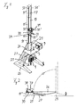
- FIG. 1 A first embodiment of a deep drilling device according to the invention is in Fig. 1 shown.
- the device has a mast support 20 with a U-shaped substructure 25, wherein the substructure 25 rests on the ground.
- two supports 26 are provided, which extend in a V-shaped manner to one another and which are articulated pivotably about a horizontal pivot axis on the substructure 25.
- At the apex of these supports 26 designed as a guide sleeve with approximately rectangular inner cross-section mast guide 21 is provided.
- this mast guide 21 a designed with approximately square outer cross section mast 10 is linearly displaceable.
- the mast carrier 20 has two hydraulic drives designed as a hydraulic cylinder 27, which are articulated on the one hand to the substructure 25 and on the other hand to the mast guide 21. These linear drives allow pivoting of the support 26 with the mast guide 21 from a in Fig. 1 shown vertical operating position in an in Fig. 2 illustrated horizontal transport position.
- a guide support 29 is provided for guiding mast members 11 described in greater detail below in the construction of the mast.
- This guide support 29 is arranged centrally with respect to the two linear drives 27.
- a work carriage 30 is mounted longitudinally displaceable on the mast 10.
- a receptacle 37 and a rotary motor 38 are provided for a drill pipe not shown in the figures on this work carriage 30.
- the in Fig. 1 consists of a total of four mast members 11, 11 ', 11 "and 11''', each having approximately the same length.A longitudinal of the individual mast members 11 to 11 '''and thus along the mast 10 extend two racks 50, 50th These toothed racks 50, 50 'are arranged in the region of a mast front side 17 of the mast 10 facing the working carriage 30. The two toothed racks 50, 50' are arranged on opposite mast sides in the area of the mast front edges formed toward the mast front side 17.
- the working carriage 30 is formed with an approximately rectangular base plate.
- a drive motor 33, 33 ', 33 ", 33” is arranged in the four corners of this base plate.
- a drive gear wheel 34 is assigned to each drive motor 33 to 33 '" in that the drive gears 34 of the motors 33, 33 'engage the right rack 50' and the drive gears 34 of the drive motors 33 ", 33"'engage the left rack 50.
- the drive motors 33 to 33 ''' form a slide drive 31 with their drive gearwheels 34.
- Fig. 1 shows the deep drilling device according to the invention on a drilling platform 5, which extends in the horizontal, and a control station 9, which is arranged on the drilling platform 5.
- the drilling platform 5 can be arranged, for example, on the lowest mast member 11. Additionally or alternatively, it may be attached to the mast carrier 20, in particular to the mast guide 21.
- a Blowoutpreventer 1 is provided below the drilling platform 5, below the drilling platform 5, a Blowoutpreventer 1 is provided below the drilling platform 5, a Blowoutpreventer 1 is provided below the drilling platform 5, a Blowoutpreventer 1 is provided below the drilling platform 5, a Blowoutpreventer 1 is provided below the drilling platform 5, a Blowoutpreventer 1 is provided below the drilling platform 5, a Blowoutpreventer 1 is provided below the drilling platform 5, a Blowoutpreventer 1 is provided below the drilling platform 5.
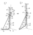
- FIGS. 3 and 4 Successive stages of the process when erecting the mast 10 of the device Fig. 1 are in the FIGS. 3 and 4 shown.
- a pivot joint 15 is provided with a horizontally extending pivot axis.
- FIGS. 3 and 4 show the work carriage 30 is established for erecting the mast relative to the mast support 20.
- a stop 40 is provided in the upper region of the mast guide 21, on which the working carriage 30 rests.
- the mast 10 lying on the ground, that is, in a horizontal position, ready to assemble and assemble the base 25, the mast support 20 and the mast guide 21.
- the support 26 is erected with the mast guide 21 by means of the linear drives 27, wherein only the uppermost mast member 11 '''is erected and the remaining mast members 11 to 11' remain folded on the ground
- Mast guide 21 connected carriage drive 31 of the mast 10 so far raised until the subsequent mast member 11 "in about is vertical.
- the two uppermost mast members 11 '''and11''are then firmly connected.
- the mast members 11 '"and 11" are moved further upwards in the direction of the drilling position by means of the carriage drive 31, so that the next following mast member 11' can also be vertically connected and connected, thus making the entire mast 10
- the mast 10 has reached its operating height and is in its drilling position, that is, in particular all the mast members 11 are in the vertical position, the mast 10 with the mast carrier 20, in particular in the mast guide 21, are firmly connected.
Landscapes
- Engineering & Computer Science (AREA)
- Life Sciences & Earth Sciences (AREA)
- Geology (AREA)
- Mining & Mineral Resources (AREA)
- Physics & Mathematics (AREA)
- Environmental & Geological Engineering (AREA)
- Fluid Mechanics (AREA)
- General Life Sciences & Earth Sciences (AREA)
- Geochemistry & Mineralogy (AREA)
- Mechanical Engineering (AREA)
- Earth Drilling (AREA)
Priority Applications (1)
| Application Number | Priority Date | Filing Date | Title |
|---|---|---|---|
| EP07016205A EP2025860A1 (fr) | 2007-08-17 | 2007-08-17 | Dispositif de forage en profondeur et procédé d'érection d'un dispositif de forage en profondeur |
Applications Claiming Priority (1)
| Application Number | Priority Date | Filing Date | Title |
|---|---|---|---|
| EP07016205A EP2025860A1 (fr) | 2007-08-17 | 2007-08-17 | Dispositif de forage en profondeur et procédé d'érection d'un dispositif de forage en profondeur |
Publications (1)
| Publication Number | Publication Date |
|---|---|
| EP2025860A1 true EP2025860A1 (fr) | 2009-02-18 |
Family
ID=38692006
Family Applications (1)
| Application Number | Title | Priority Date | Filing Date |
|---|---|---|---|
| EP07016205A Withdrawn EP2025860A1 (fr) | 2007-08-17 | 2007-08-17 | Dispositif de forage en profondeur et procédé d'érection d'un dispositif de forage en profondeur |
Country Status (1)
| Country | Link |
|---|---|
| EP (1) | EP2025860A1 (fr) |
Cited By (2)
| Publication number | Priority date | Publication date | Assignee | Title |
|---|---|---|---|---|
| ITTO20120414A1 (it) * | 2012-05-09 | 2013-11-10 | Drillmec Spa | Apparato di trivellazione e metodo di assemblaggio e disassemblaggio. |
| CN116255093A (zh) * | 2023-02-27 | 2023-06-13 | 浙江正匠建设工程有限公司 | 一种特殊地质旋挖桩装置及工艺 |
Citations (3)
| Publication number | Priority date | Publication date | Assignee | Title |
|---|---|---|---|---|
| DE1228040B (de) * | 1961-09-19 | 1966-11-03 | Markus Schmidt Tychsen Derrick | Kran, dessen Saeule aus einer Mehrzahl von Mastelementen aufgebaut ist |
| DE1481809A1 (de) * | 1966-02-24 | 1969-09-04 | Richier Fa | Vorrichtung zum Aufrichten und Umlegen von Masten oder Gittermasten,anwendbar insbesondere bei Kraenen und Hebezeugen |
| DE9110495U1 (de) * | 1991-08-24 | 1991-10-17 | Ing. G. Klemm, Bohrtechnik GmbH, 5962 Drolshagen | Fahrbares Bohrgerät |
-
2007
- 2007-08-17 EP EP07016205A patent/EP2025860A1/fr not_active Withdrawn
Patent Citations (3)
| Publication number | Priority date | Publication date | Assignee | Title |
|---|---|---|---|---|
| DE1228040B (de) * | 1961-09-19 | 1966-11-03 | Markus Schmidt Tychsen Derrick | Kran, dessen Saeule aus einer Mehrzahl von Mastelementen aufgebaut ist |
| DE1481809A1 (de) * | 1966-02-24 | 1969-09-04 | Richier Fa | Vorrichtung zum Aufrichten und Umlegen von Masten oder Gittermasten,anwendbar insbesondere bei Kraenen und Hebezeugen |
| DE9110495U1 (de) * | 1991-08-24 | 1991-10-17 | Ing. G. Klemm, Bohrtechnik GmbH, 5962 Drolshagen | Fahrbares Bohrgerät |
Cited By (5)
| Publication number | Priority date | Publication date | Assignee | Title |
|---|---|---|---|---|
| ITTO20120414A1 (it) * | 2012-05-09 | 2013-11-10 | Drillmec Spa | Apparato di trivellazione e metodo di assemblaggio e disassemblaggio. |
| WO2013168064A3 (fr) * | 2012-05-09 | 2014-05-22 | Drillmec S.P.A. | Appareil de forage de puits et méthode de montage et de démontage |
| CN104520524A (zh) * | 2012-05-09 | 2015-04-15 | 吉尔迈科股份公司 | 钻井设备以及组装和拆卸方法 |
| CN116255093A (zh) * | 2023-02-27 | 2023-06-13 | 浙江正匠建设工程有限公司 | 一种特殊地质旋挖桩装置及工艺 |
| CN116255093B (zh) * | 2023-02-27 | 2024-01-23 | 浙江正匠建设工程有限公司 | 一种特殊地质旋挖桩装置及工艺 |
Similar Documents
| Publication | Publication Date | Title |
|---|---|---|
| EP2146027B1 (fr) | Appareil de construction doté d'un mât pivotant | |
| EP2133508B1 (fr) | Appareil de construction doté d'un mât téléscopique et procédé de fonctionnement d'un tel appareil | |
| DE69101569T2 (de) | Hebevorrichtung. | |
| DE69408453T2 (de) | Höhenverstellbare Arbeitsvorrichtung | |
| DE69710904T2 (de) | Anordnung für eine mobile veranstaltungseinheit | |
| EP3401444B1 (fr) | Dispositif d'excavation de tranchée et procédé de fabrication de tranchées dans le sol | |
| DE112013002136T5 (de) | Entlang Zahnstangen bewegbarer Bohrplattform-Schlitten mit von Elektromotoren angetriebenen Ritzeln | |
| EP2845952A1 (fr) | Machine à coffrage glissant, et procédé d'adaptation de la largeur d'une poutre dameuse | |
| EP0208228A2 (fr) | Wagon surbaissé | |
| DE19525594A1 (de) | Motorisiertes Instandsetzungsgerät, insbesondere zur Instandsetzung eines Panzers | |
| DE102006062771B4 (de) | Hubstützenbock, insbesondere für einen Universaltragrahmen | |
| EP1371305B1 (fr) | Table extensible | |
| DE3906616C2 (fr) | ||
| EP2025860A1 (fr) | Dispositif de forage en profondeur et procédé d'érection d'un dispositif de forage en profondeur | |
| DE68903372T2 (de) | Zusammenlegbarer kran mit einem ausleger, bestehend aus zwei oder drei gelenkig miteinander verbundenen elementen. | |
| EP2025859A1 (fr) | Dispositif de forage en profondeur et procédé de création d'un dispositif de forage en profondeur | |
| EP1293471B1 (fr) | Flèche télescopique | |
| DE60001179T2 (de) | Herausziehungsvorrichtung für wärmetauscherrohrbündel | |
| DE102011100691A1 (de) | Bohrgerät und Verfahren zum Betreiben eines Bohrgeräts | |
| DE29718149U1 (de) | Fahrbares Arbeitsgerät | |
| DE1481809B2 (de) | Vorrichtung zum Aufstellen und Umlegen von Masten, insbesondere eines Baukranmastes | |
| DE10011650B4 (de) | Kran | |
| DE3200540C2 (de) | Vorrichtung zum Verschließen von Behältern mit Stöpseln | |
| EP2039875A1 (fr) | Dispositif de forage, en particulier dispositif de forage profond | |
| DE4342016A1 (de) | Vorrichtung zum Verstellen der Höhe und/oder Neigung einer Tischplatte |
Legal Events
| Date | Code | Title | Description |
|---|---|---|---|
| PUAI | Public reference made under article 153(3) epc to a published international application that has entered the european phase |
Free format text: ORIGINAL CODE: 0009012 |
|
| AK | Designated contracting states |
Kind code of ref document: A1 Designated state(s): AT BE BG CH CY CZ DE DK EE ES FI FR GB GR HU IE IS IT LI LT LU LV MC MT NL PL PT RO SE SI SK TR |
|
| AX | Request for extension of the european patent |
Extension state: AL BA HR MK RS |
|
| AKX | Designation fees paid | ||
| STAA | Information on the status of an ep patent application or granted ep patent |
Free format text: STATUS: THE APPLICATION IS DEEMED TO BE WITHDRAWN |
|
| 18D | Application deemed to be withdrawn |
Effective date: 20090819 |
|
| REG | Reference to a national code |
Ref country code: DE Ref legal event code: 8566 |