EP2026046B1 - Capteur de niveau à radar avec des paramètres d'impulsion variables - Google Patents
Capteur de niveau à radar avec des paramètres d'impulsion variables Download PDFInfo
- Publication number
- EP2026046B1 EP2026046B1 EP08161447.1A EP08161447A EP2026046B1 EP 2026046 B1 EP2026046 B1 EP 2026046B1 EP 08161447 A EP08161447 A EP 08161447A EP 2026046 B1 EP2026046 B1 EP 2026046B1
- Authority
- EP
- European Patent Office
- Prior art keywords
- pulse
- pulse width
- tank
- filling
- transmitter
- Prior art date
- Legal status (The legal status is an assumption and is not a legal conclusion. Google has not performed a legal analysis and makes no representation as to the accuracy of the status listed.)
- Active
Links
Images


Classifications
-
- G—PHYSICS
- G01—MEASURING; TESTING
- G01F—MEASURING VOLUME, VOLUME FLOW, MASS FLOW OR LIQUID LEVEL; METERING BY VOLUME
- G01F23/00—Indicating or measuring liquid level or level of fluent solid material, e.g. indicating in terms of volume or indicating by means of an alarm
- G01F23/22—Indicating or measuring liquid level or level of fluent solid material, e.g. indicating in terms of volume or indicating by means of an alarm by measuring physical variables, other than linear dimensions, pressure or weight, dependent on the level to be measured, e.g. by difference of heat transfer of steam or water
- G01F23/28—Indicating or measuring liquid level or level of fluent solid material, e.g. indicating in terms of volume or indicating by means of an alarm by measuring physical variables, other than linear dimensions, pressure or weight, dependent on the level to be measured, e.g. by difference of heat transfer of steam or water by measuring the variations of parameters of electromagnetic or acoustic waves applied directly to the liquid or fluent solid material
- G01F23/284—Electromagnetic waves
-
- G—PHYSICS
- G01—MEASURING; TESTING
- G01F—MEASURING VOLUME, VOLUME FLOW, MASS FLOW OR LIQUID LEVEL; METERING BY VOLUME
- G01F25/00—Testing or calibration of apparatus for measuring volume, volume flow or liquid level or for metering by volume
- G01F25/20—Testing or calibration of apparatus for measuring volume, volume flow or liquid level or for metering by volume of apparatus for measuring liquid level
-
- G—PHYSICS
- G01—MEASURING; TESTING
- G01S—RADIO DIRECTION-FINDING; RADIO NAVIGATION; DETERMINING DISTANCE OR VELOCITY BY USE OF RADIO WAVES; LOCATING OR PRESENCE-DETECTING BY USE OF THE REFLECTION OR RERADIATION OF RADIO WAVES; ANALOGOUS ARRANGEMENTS USING OTHER WAVES
- G01S13/00—Systems using the reflection or reradiation of radio waves, e.g. radar systems; Analogous systems using reflection or reradiation of waves whose nature or wavelength is irrelevant or unspecified
- G01S13/02—Systems using reflection of radio waves, e.g. primary radar systems; Analogous systems
- G01S13/06—Systems determining position data of a target
- G01S13/08—Systems for measuring distance only
- G01S13/10—Systems for measuring distance only using transmission of interrupted, pulse modulated waves
- G01S13/106—Systems for measuring distance only using transmission of interrupted, pulse modulated waves using transmission of pulses having some particular characteristics
-
- G—PHYSICS
- G01—MEASURING; TESTING
- G01S—RADIO DIRECTION-FINDING; RADIO NAVIGATION; DETERMINING DISTANCE OR VELOCITY BY USE OF RADIO WAVES; LOCATING OR PRESENCE-DETECTING BY USE OF THE REFLECTION OR RERADIATION OF RADIO WAVES; ANALOGOUS ARRANGEMENTS USING OTHER WAVES
- G01S13/00—Systems using the reflection or reradiation of radio waves, e.g. radar systems; Analogous systems using reflection or reradiation of waves whose nature or wavelength is irrelevant or unspecified
- G01S13/88—Radar or analogous systems specially adapted for specific applications
-
- G—PHYSICS
- G01—MEASURING; TESTING
- G01S—RADIO DIRECTION-FINDING; RADIO NAVIGATION; DETERMINING DISTANCE OR VELOCITY BY USE OF RADIO WAVES; LOCATING OR PRESENCE-DETECTING BY USE OF THE REFLECTION OR RERADIATION OF RADIO WAVES; ANALOGOUS ARRANGEMENTS USING OTHER WAVES
- G01S7/00—Details of systems according to groups G01S13/00, G01S15/00, G01S17/00
- G01S7/02—Details of systems according to groups G01S13/00, G01S15/00, G01S17/00 of systems according to group G01S13/00
- G01S7/28—Details of pulse systems
- G01S7/282—Transmitters
Definitions
- the present invention relates to a pulsed radar level gauge system and a corresponding method.
- Radar level gauging to measure the level of a filling material, such as a liquid or a solid like a granulate is an increasingly important method for level gauging in tanks, containers, etc.
- RLG Radar level gauging
- continuously emitted radiation, and in particular FMCW is used for most applications.
- pulsed RLG is becoming a more widely spread method for industrial level gauging, due to its simple and cost effective microwave components.
- the pulse in a pulsed RLG can be modulated by a carrier frequency, typically 6 or 24 GHz, or be an unmodulated DC pulse.
- transmission line such as a coaxial line, twin line, etc., sometimes referred to as a probe
- a transmission line or wave guide can also be used, but generally an antenna is used to freely emit radiation in the form of a vertical radar beam which is reflected at possible interface surfaces.
- pulsed radars typically have lower sensitivity compared to frequency modulated continuous wave (FMCW) radar.
- the sensitivity i.e. the ability to detect weak reflections, is an important virtue for any RLG as a high sensitivity may enable the use of a smaller antenna or a longer transmission line, all other parameters held constant. Accordingly, various attempts have been made to improve the sensitivity of pulsed RLG systems.
- US 2006/0055591 by the same applicant discloses an improved type of directional coupler, providing increased sensitivity to the system JP 2002 372578 A discloses a RLG method and apparatus which conducts level gauging with many different pulse widths on an individual measurement basis.
- a method for determining a filling level of a filling material in a tank comprising the steps:
- the present invention is particularly advantageous for applications where several levels are to be measured, e.g. due to several different material interfaces in the tank.
- the present invention e.g. enables automated production tests, since the pulse width can be changed during operation, without specific tools etc.
- the pulse width adjustment functionality can be used in a system where the pulse width is continuously controlled in order to achieve an optimized map of resolution and sensitivity, and for obtain an optimized choice of the pulse width. For example, this allows targets of interest that provide weak echoes to be emitted with more energy, and vice versa. Targets that are close in terms of distances, can be better distinguished if the pulse width is shortened.
- the system functionality can be made adaptive, in order to obtain an optimized resolution / sensitivity at all times, and for all types of application conditions.
- one advantageous way of using the present invention is to provide an easy adaptation of the pulse width of a general radar level gauge system to a known measuring situation, wherein fixed settings may be used.
- Another advantageous way of using the present invention is to provide automatic and/or adaptive control, by means of e.g. scanning the total range or a sub-range of the levels of the tank width different pulse widths, in order to find an optimal choice for a specific situation.
- the control of the pulse width can be linear or stepwise, e.g. for a number of certain typical situations. Automatic control of the pulse width may also be based on measurements related to the specific conditions at hand.
- the pulse width adjustment comprises the sub-steps of: controlling the pulse width to at least two different widths; determining the filling level of the tank based on said received echo pulse signals using each of said different pulse widths; and selecting, based on said determinations of the filling level, one of said pulse widths to be used for subsequent filling level determination.
- a scanning is made with a multitude of different pulse widths.
- the most suitable pulse width can be selected in an automatic fashion. For example, this enables an initial scanning of the tank with a relatively large pulse width, in order to obtain a general overview of where the surface interfaces etc are. Thereafter, narrower pulses can be selected, at least for specific level ranges, in order to obtain an optimized resolution.
- the scanning preferably involves a multifold repetition over time of the steps of controlling the pulse width and determining the filling level for each of said different pulse widths, where after a pulse width optimized for the present conditions can be selected.
- the pulse width of generated pulses in accordance with at least one application specific condition comprises the further steps: controlling the pulse width of generated pulses to be a first pulse width; transmitting said pulses having said first pulse width towards said filling material; receiving reflected echo pulse signals from the tank; and determining a first measure of the filling level of the tank based on said received echo pulse signals; and determining a second pulse width to be used for subsequent pulses based on said first measure of the filling level.
- a suitable pulse width can also be determined automatically.
- the pulse width is decreased in continuous or incremental steps, wherein said first pulse width is longer than said second pulse width.
- the pulse is preferably a modulated pulse, even though non-modulated pulses are also feasible.
- a radar level gauge system for determining a filling level of a filling material in a tank, comprising:
- Fig 1a and 1b show schematically a radar level gauge (RLG) system 2 according to the present invention.
- the radar level gauge system comprises an electronic unit 3 for transmitting and receiving radar signals and processing the received signals in order to determine the level of a filling material in the tank 1.
- the system 2 is arranged to perform measurements of one or several level of a filling material, such as the level of an interface between two (or more) materials in the tank.
- the first material is a content stored in the tank, e.g. a liquid such as gasoline, while the second material is air or some other atmosphere.
- the RLG will enable detection of the level of the surface of the content in the tank.
- different tank content have different impedance, and the electromagnetic waves will not propagate through any material in the tank.
- only the level of a first liquid surface is measured, or a second liquid surface if the first liquid is sufficiently transparent.
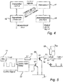
- the RLG system 2 comprises a transceiver 41, controlled by a processor 42 to transmit electromagnetic signals to a signal medium interface 43 in the tank.
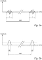
- the signals can be DC pulses, as illustrated in fig 3b , with a pulse width ⁇ , i.e. a length in time, which is preferably about 2 ns or less.
- the pulses are repeated with a frequency in the order of MHz, at average power levels in the mW or ⁇ W area, and the timely separation between the start of two sequential pulses, denoted PRF in the drawings, is significantly longer than the pulse width ⁇ .
- the pulses can be modulated on a carrier wave, preferably of a GHz frequency, as is illustrated in fig 3a .
- the transceiver 41 can comprise various components, as is per se known in the art.
- the transceiver circuit can comprise separate receiver and transmitter circuits, or a common transceiver circuit.
- the transceiver preferably comprises a transmit/receive (TR) coupler which connects the transmitter and the receiver with the antenna/probe interface 43.
- TR-coupler can be a directional coupler, a ferrite circulator, a switch or any other conventional component.
- the transceiver also includes a pulse width adjuster, as discussed in more detail in the following.
- the signal medium interface 43 is connected to a wave guiding structure or probe 4 extending into the content of the tank.
- the wave guiding structure can be a hollow wave guide or some sort of probe, such as a coaxial wire probe, a twin wire probe, or a single wire probe (also referred to as a surface wave guide). Electromagnetic waves transmitted along the structure 4 will be reflected by any interface between materials in the tank, and the reflection will be transmitted back to the signal medium interface 43.
- the signal medium interface 43 is connected to a radar antenna 5, arranged to emit the transmitted waves to freely propagate into the tank, and to receive waves that are reflected by any interface between materials in the tank.
- the pulses are typically modulated on a high frequency carrier wave, as illustrated in fig 3a .
- the antenna 5 is arranged inside the tank for transmitting and receiving radar waves into the tank, and a radar wave guide assembly 6 may be arranged for guiding signals between the electronic unit 3 and the antenna 5.
- the same antenna could preferably be used both as a transmitter for emitting the output radiation and as a receiver for receiving the reflected echo signal, even though it is also possible to use separate antennas for these functions.
- the radar level gauge 2 transmits radar energy along the waveguide 5 through the tank roof port and receives reflected energy from the liquid surface(s) to provide an indication of the level of the liquid within the tank.
- the radar level gauge 2 could be coupled to a remote location (for example a control room) via a signal wire or the like.
- a reflection pulse received by the signal medium interface is fed back to the transceiver 41, where it is sampled and digitalized in a process controlled by a processor (not shown).
- a processor not shown
- the distance is calculated by time measurement of the time it takes for a short wave microwave pulse to travel to the target, such as the surface level, and be reflected back to the gauge.
- a digitalized, sampled time domain reflectometry (TDR) signal based on the reflected signal can be communicated back to the processor 42.
- TDR sampled time domain reflectometry
- the processor 42 is preferably provided with software for analyzing the TDR signal in order to determine a process variable in the tank, typically the level of the surface.
- the processor can also be connected to a user interface, a remote station or the like.
- the RLG system is arranged to perform measurements of two or more levels of a filling material.
- a highest layer comprises a first material, such as air or any other gas, having a first impedance ⁇ 0
- an intermediate layer of a second material such as foam or a liquid of low density
- a lower layer of a third material such as gasoline or any other liquid
- two different levels a and b are detectable in this situation.
- FIG. 1b A similar situation is illustrated in fig 1b .
- the liquid level is denoted a', and a tank structure, such as a moving stirring device, is arranged on a different level b'.
- a similar problem arises: echoes resulting from pulses with a smaller ⁇ result in echoes of lower signal power, but which are clearly distinguishable, whereas a larger ⁇ results in higher signal power, but where it is difficult or even impossible to distinguish between the different levels a' and b', as is illustrated in fig 2b .
- the strength of an echo signal is generally equal to amplitude multiplied with pulse time. Consequently, we want to amplify weak echoes with longer pulse times to be able to distinguish these targets.
- resolution decreases with an increased ⁇ and increases with a decreased ⁇ .
- the RLG further comprises means for controlling the pulse generator for adjusting the pulse width of generated pulses in accordance with at least one application specific condition, as will be discussed more thoroughly in the following.
- said means for controlling the pulse width are preferably arranged in the pulse forming part of the transceiver circuitry 41, as discussed in the foregoing.
- a pulse generator or oscillator 51 for the provision of short DC input clock pulses, which determine the pulse repetition frequency.
- the input pulses are forwarded via a controllable delay 52 to the base of a first transistor (V1) 53 of npn-type.
- the delay provided in the controllable delay 52 is adjustable, and controlled by an input control signal.
- the input clock signal is also forwarded via a first resistance (R1) 54 to the base of a second transistor (V2) 55, also of npn-type, together with an output signal from the collector of the first transistor 53.
- the emitter of the first and second transistors are connected to ground.
- the output of the collector of the second transistor is forwarded via a second resistance (R2) 56 to the base of a third transistor (V3) 57, which is of pnp-type.
- the base and emitter of the third transistor are connected via a third resistance (R3) 58.
- the first two transistors provide a positive output signal, interrupted by short pulses, and the third transistor provides an inverse signal, having short positive pulses, and provides an increased output ability of the circuit.
- the signal to the base of the first transistor 53 is delayed by means of the controllable delay 52.
- the second transistor 55 is switched on.
- the first transistor shunts the drive voltage to the second transistor.
- the result is an output signal with the same repetition frequency as the input clock signal, but with a shorter pulse width.
- the length of the pulse width can be controlled by means of the delay provided by the controllable delay circuit 52, which in turn is dependent on the control signal provided.
- the controllable delay 52 may be realized as e.g. a component that controls the threshold of the first transistor or electrically controls a variable resistance, i.e. a potentionmeter, such as a digital potentionmeter arranged ahead of the base of the first transistor.
- the output of the pulse generator may be connected to a fast switch which is controllable to control one or both of the ends of the pulse, thereby to control the pulse length.
- a fast switch which is controllable to control one or both of the ends of the pulse, thereby to control the pulse length.
- Other alternatives using variable capacitors and the like are also feasible.
- the pulse width may be adjusted for a number of application specific conditions, such as tank height, level of filling material, the presence of several different interface levels, types of materials, different impedances, other tank structure providing reflecting surfaces, type of measurement required, such as general scan, measurement of specific surfaces etc.
Landscapes
- Physics & Mathematics (AREA)
- Engineering & Computer Science (AREA)
- Radar, Positioning & Navigation (AREA)
- Remote Sensing (AREA)
- General Physics & Mathematics (AREA)
- Electromagnetism (AREA)
- Computer Networks & Wireless Communication (AREA)
- Fluid Mechanics (AREA)
- Thermal Sciences (AREA)
- Measurement Of Levels Of Liquids Or Fluent Solid Materials (AREA)
- Radar Systems Or Details Thereof (AREA)
Claims (16)
- Procédé pour déterminer un niveau de remplissage d'un produit de remplissage dans un réservoir, comprenant les étapes suivantes :la fourniture d'un générateur d'impulsions pour la génération d'impulsions électromagnétiques ;le contrôle de la largeur d'impulsion des impulsions générées en fonction d'au moins une condition spécifique d'utilisation ;la transmission desdites impulsions avec une largeur d'impulsion ajustée vers ledit produit de remplissage ;la réception de signaux impulsionnels d'écho réfléchis dudit réservoir ; etla détermination du niveau de remplissage du réservoir sur la base desdits signaux impulsionnels d'écho reçus,dans lequel la largeur d'impulsion est ajustée pour au moins une condition spécifique d'utilisation sélectionnée dans le groupe formé par une hauteur du réservoir, un niveau de remplissage avec le produit, le type de produit de remplissage, la présence d'une autre structure de réservoir fournissant des surfaces réfléchissantes, et une exactitude de mesure requise.
- Procédé selon la revendication 1, dans lequel l'ajustement de la largeur d'impulsion comprend les sous-étapes suivantes :le contrôle de la largeur d'impulsion à au moins deux largeurs différentes ;la détermination du niveau de remplissage du réservoir sur la base desdits signaux impulsionnels d'écho reçus en utilisant chacune desdites largeurs d'impulsion différentes ; etla sélection, sur la base desdites déterminations du niveau de remplissage, d'une desdites largeurs d'impulsion à utiliser pour une détermination de niveau de remplissage subséquente.
- Procédé selon la revendication 2, dans lequel l'étape de contrôle de la largeur d'impulsion à différentes largeurs et de détermination du niveau de remplissage pour chacune desdites largeurs d'impulsion différentes sont répétées pour effectuer un balayage parmi une pluralité de largeurs d'impulsion différentes.
- Procédé selon l'une quelconque des revendications 1-3, dans lequel l'étape de contrôle de la largeur d'impulsion d'impulsions générées en fonction d'au moins une condition spécifique d'utilisation comprend les autres étapes suivantes :le contrôle de la largeur d'impulsion d'impulsions générées pour être d'une première largeur d'impulsion ;la transmission desdites impulsions ayant ladite première largeur d'impulsion vers ledit produit de remplissage ;la réception de signaux impulsionnels d'écho réfléchis du réservoir ; etla détermination d'une première mesure du niveau de remplissage du réservoir sur la base desdits signaux impulsionnels d'écho reçus ; etla détermination d'une deuxième largeur d'impulsion à utiliser pour des impulsions subséquentes sur la base de ladite première mesure du niveau de remplissage.
- Procédé selon la revendication 4, dans lequel ladite première largeur d'impulsion est supérieure à ladite deuxième largeur d'impulsion.
- Procédé selon l'une quelconque des revendications 1-5, dans lequel le contrôle de la largeur d'impulsion d'impulsions générées en fonction d'au moins une condition spécifique d'utilisation est réalisé automatiquement sur la base d'une mesure relative à ladite condition spécifique d'utilisation.
- Procédé selon l'une quelconque des revendications 1-6, dans lequel ladite impulsion est une impulsion modulée.
- Système de jauge de niveau à radar pour déterminer un niveau de remplissage d'un produit de remplissage dans un réservoir, comprenant :un émetteur pour générer et transmettre un signal impulsionnel d'émetteur électromagnétique, dans lequel l'émetteur comprend un générateur d'impulsions et un moyen pour l'ajustement de la largeur d'impulsion ;un contrôleur d'émetteur pour contrôler le moyen pour l'ajustement de la largeur d'impulsion afin d'ajuster la largeur d'impulsion du signal impulsionnel d'émetteur en fonction d'au moins une condition spécifique d'utilisation ;une interface signal-milieu pouvant être connectée au moyen pour diriger ledit signal impulsionnel d'émetteur vers ledit produit de remplissage et pour recevoir un signal impulsionnel de réception renvoyé par ledit produit de remplissage ;un récepteur pour recevoir ledit signal impulsionnel de réception du réservoir ; etun circuit de traitement pour déterminer le niveau de remplissage du réservoir sur la base dudit signal impulsionnel de réflexion reçu par ledit récepteur,dans lequel le contrôleur d'émetteur est étudié pour ajuster la largeur d'impulsion en fonction d'au moins une condition spécifique d'utilisation sélectionnée dans le groupe formé par une hauteur du réservoir, un niveau du produit de remplissage, un type de produit de remplissage, la présence d'une autre structure de réservoir fournissant des surfaces réfléchissantes, et l'exactitude requise de la mesure.
- Système de jauge de niveau à radar de la revendication 8, dans lequel le contrôleur d'émetteur est étudié pour contrôler la largeur d'impulsion à au moins deux largeur différentes et sélectionner, sur la base de déterminations du niveau de remplissage du réservoir sur la base de signaux impulsionnels d'écho reçus en utilisant chacune desdites largeurs d'impulsion différentes, l'une desdites largeurs d'impulsion à utiliser pour une détermination de niveau de remplissage subséquente.
- Système de jauge de niveau à radar selon la revendication 9, dans lequel le contrôleur d'émetteur est étudié pour contrôler la largeur d'impulsion afin de varier dans le temps de sorte qu'un balayage est effectué parmi une pluralité de largeurs d'impulsion différentes.
- Système de jauge de niveau à radar de l'une quelconque des revendications 8-10, dans lequel le contrôleur d'émetteur est étudié pour contrôler la largeur d'impulsion des impulsions générées pour être d'une première largeur d'impulsion et déterminer une deuxième largeur d'impulsion à utiliser pour des impulsions subséquentes sur la base d'une première mesure du niveau de remplissage sur la base de ladite première largeur d'impulsion.
- Jauge de niveau à radar de la revendication 11, dans laquelle ladite première largeur d'impulsion est supérieure à ladite deuxième largeur d'impulsion.
- Système de jauge de niveau à radar de l'une quelconque des revendications 8-12, dans lequel le contrôleur d'émetteur est étudié pour automatiquement contrôler la largeur d'impulsion d'impulsions générées en fonction de l'au moins une condition spécifique d'utilisation.
- Système de jauge de niveau à radar selon l'une quelconque des revendications 8-13, dans lequel le moyen pour diriger le signal impulsionnel d'émetteur vers le produit de remplissage comprend une antenne.
- Système de jauge de niveau à radar de l'une quelconque des revendications 8-14, dans lequel le moyen pour diriger le signal impulsionnel d'émetteur vers le produit de remplissage comprend une sonde.
- Système de jauge de niveau à radar de l'une quelconque des revendications 8-15, comprenant en outre un moyen pour moduler l'impulsion.
Applications Claiming Priority (1)
| Application Number | Priority Date | Filing Date | Title |
|---|---|---|---|
| US11/831,053 US7800528B2 (en) | 2007-07-31 | 2007-07-31 | Radar level gauge with variable pulse parameters |
Publications (3)
| Publication Number | Publication Date |
|---|---|
| EP2026046A2 EP2026046A2 (fr) | 2009-02-18 |
| EP2026046A3 EP2026046A3 (fr) | 2013-04-10 |
| EP2026046B1 true EP2026046B1 (fr) | 2021-03-24 |
Family
ID=40001497
Family Applications (1)
| Application Number | Title | Priority Date | Filing Date |
|---|---|---|---|
| EP08161447.1A Active EP2026046B1 (fr) | 2007-07-31 | 2008-07-30 | Capteur de niveau à radar avec des paramètres d'impulsion variables |
Country Status (2)
| Country | Link |
|---|---|
| US (1) | US7800528B2 (fr) |
| EP (1) | EP2026046B1 (fr) |
Families Citing this family (29)
| Publication number | Priority date | Publication date | Assignee | Title |
|---|---|---|---|---|
| US7823446B2 (en) * | 2006-11-06 | 2010-11-02 | Rosemount Tank Radar Ab | Pulsed radar level gauging with relative phase detection |
| ES2524827T3 (es) * | 2009-12-18 | 2014-12-12 | Total Research & Technology Feluy | Procedimiento de supervisión del nivel de una suspensión de catalizador de polimerización de etileno |
| US8830118B2 (en) * | 2010-09-07 | 2014-09-09 | Rosemount Tank Radar Ab | Radar level gauge system with operation monitoring functionality |
| US8701483B2 (en) * | 2010-12-16 | 2014-04-22 | Vega Grieshaber Kg | Device for emulsion measuring by means of a standpipe |
| US20130057425A1 (en) * | 2011-09-06 | 2013-03-07 | Fabian Wenger | Pulsed level gauge system with controllable delay path through selected number of delay cells |
| US8692983B1 (en) * | 2011-09-13 | 2014-04-08 | Rockwell Collins, Inc. | Optical, laser-based, or lidar measuring systems and method |
| US8726728B2 (en) * | 2012-03-13 | 2014-05-20 | Rosemount Tank Radar Ab | Level gauge system with wettable propagation device |
| DE102012007979A1 (de) * | 2012-04-24 | 2013-10-24 | Krohne Messtechnik Gmbh | Verfahren zur Bestimmung des Füllstandes eines Mediums und entsprechende Vorrichtung |
| US9024806B2 (en) * | 2012-05-10 | 2015-05-05 | Rosemount Tank Radar Ab | Radar level gauge with MCU timing circuit |
| US8963769B2 (en) * | 2012-10-16 | 2015-02-24 | Magnetrol International, Incorporated | Guided wave radar interface measurement medium identification |
| HUE028118T2 (en) * | 2013-08-14 | 2016-11-28 | Grieshaber Vega Kg | Radar beam diverting unit for charge level gauge |
| US9329072B2 (en) * | 2013-12-06 | 2016-05-03 | Honeywell International Inc. | Receiver with programmable gain for UWB radar |
| US9329073B2 (en) * | 2013-12-06 | 2016-05-03 | Honeywell International Inc. | Adaptive radar system with mutliple waveforms |
| US9329074B2 (en) | 2013-12-06 | 2016-05-03 | Honeywell International Inc. | Multi-mode pulsed radar providing automatic transmit pulse signal control |
| US9778089B2 (en) * | 2014-06-30 | 2017-10-03 | Rosemount Tank Radar Ab | Multi-channel guided wave radar level gauge |
| US20160097670A1 (en) * | 2014-10-01 | 2016-04-07 | Honeywell International Inc. | Resolution mode switching for pulsed radar |
| US9638567B2 (en) * | 2014-10-14 | 2017-05-02 | Rosemount Tank Radar Ab | Radar level gauge with foldable probe |
| US10055519B2 (en) * | 2014-10-23 | 2018-08-21 | Honeywell International Inc. | Pulse shape change for interface determination |
| EP3067711B1 (fr) * | 2015-03-13 | 2019-12-18 | Honeywell International Inc. | Appareil et procédé de réglage de largeur d'impulsion radar à ondes guidées pour optimiser des mesures |
| US20160305812A1 (en) * | 2015-04-17 | 2016-10-20 | Honeywell Asca Inc. | Multiplexed level sensing probes |
| DE102015109480B3 (de) * | 2015-06-15 | 2016-08-25 | Endress + Hauser Gmbh + Co. Kg | Verfahren und Vorrichtung zur Bestimmung des Füllstandes eines in einem Behälter befindlichen Füllgutes |
| US10444055B2 (en) | 2015-09-11 | 2019-10-15 | Honeywell International Inc. | Apparatus and method to detect liquid material at the end of the waveguide in a guided wave radar system |
| DE102016103740B3 (de) * | 2016-03-02 | 2017-05-04 | Endress+Hauser Gmbh+Co. Kg | Verfahren zur Messung des Füllstands eines in einem Behälter befindlichen Füllgutes mittels Terahertz-Pulsen |
| US10634542B2 (en) | 2016-06-22 | 2020-04-28 | Honeywell International Inc. | Adaptive sync control in radar level sensors |
| EP3418700B1 (fr) * | 2017-06-21 | 2026-03-04 | VEGA Grieshaber KG | Appareil de radiodétection de niveau de remplissage à adaptation automatique de la fréquence |
| EP3751242B1 (fr) | 2019-06-11 | 2021-12-29 | Rosemount Tank Radar AB | Jauge de niveau radar à ondes guidées comportant un boîtier antidéflagrant ayant une sortie intrinsèquement sécurisée |
| EP3795956B1 (fr) * | 2019-09-19 | 2023-06-28 | Rosemount Tank Radar AB | Jauge de niveau à radar pulsé avec rétroaction de l'impulsion d'émission |
| EP3848720B1 (fr) * | 2020-01-13 | 2025-11-12 | Rosemount Tank Radar AB | Jauge de niveau radar à ondes guidées et procédé de commande de la jauge de niveau radar à ondes guidées |
| DE102020114108A1 (de) * | 2020-05-26 | 2021-12-02 | Endress+Hauser SE+Co. KG | Füllstandsmessgerät |
Family Cites Families (14)
| Publication number | Priority date | Publication date | Assignee | Title |
|---|---|---|---|---|
| US3296862A (en) * | 1963-10-02 | 1967-01-10 | Atomic Power Dev Ass Inc | Fluid level measuring apparatus |
| US3739379A (en) * | 1971-02-03 | 1973-06-12 | Hoffman Electronics Corp | Coherent pulse doppler altimeter |
| US3946322A (en) | 1974-06-17 | 1976-03-23 | The United States Of America As Represented By The Secretary Of The Navy | Pulse duty cycle transition moderating device |
| US3985030A (en) * | 1974-10-29 | 1976-10-12 | William Mcgeoch & Company | Ultrasonic acoustic pulse echo ranging system |
| US4001821A (en) | 1975-06-16 | 1977-01-04 | The United States Of America As Represented By The Secretary Of The Air Force | High power microwave radar pulse shaping system |
| JPH02275381A (ja) | 1989-04-18 | 1990-11-09 | Mitsubishi Electric Corp | 機上用レーダ装置 |
| US4984449A (en) * | 1989-07-03 | 1991-01-15 | Caldwell System Corp. | Ultrasonic liquid level monitoring system |
| JP2758308B2 (ja) | 1992-04-15 | 1998-05-28 | 三菱電機株式会社 | レーダー装置 |
| JPH0792252A (ja) | 1993-09-22 | 1995-04-07 | Japan Radio Co Ltd | 船舶用レーダ送信機 |
| JP2002372578A (ja) * | 2001-06-15 | 2002-12-26 | Kaijo Corp | 距離計 |
| DE10220073A1 (de) * | 2002-05-04 | 2003-11-13 | Bosch Gmbh Robert | Short-Range-Radarsystem mit variabler Pulsdauer |
| US6995706B2 (en) * | 2004-02-13 | 2006-02-07 | Saab Rosemount Tank Radar Ab | Method and an arrangement in a radar level gauging system |
| US7233278B2 (en) | 2004-09-10 | 2007-06-19 | Rosemount Tank Radar Ab | Radar level gauge with switch for selecting transmitter or receiver mode |
| JP2007170819A (ja) * | 2005-12-19 | 2007-07-05 | Tdk Corp | パルス波レーダー装置 |
-
2007
- 2007-07-31 US US11/831,053 patent/US7800528B2/en active Active
-
2008
- 2008-07-30 EP EP08161447.1A patent/EP2026046B1/fr active Active
Non-Patent Citations (1)
| Title |
|---|
| None * |
Also Published As
| Publication number | Publication date |
|---|---|
| EP2026046A3 (fr) | 2013-04-10 |
| EP2026046A2 (fr) | 2009-02-18 |
| US7800528B2 (en) | 2010-09-21 |
| US20090033543A1 (en) | 2009-02-05 |
Similar Documents
| Publication | Publication Date | Title |
|---|---|---|
| EP2026046B1 (fr) | Capteur de niveau à radar avec des paramètres d'impulsion variables | |
| US7233278B2 (en) | Radar level gauge with switch for selecting transmitter or receiver mode | |
| US5609059A (en) | Electronic multi-purpose material level sensor | |
| US5689265A (en) | Device for measuring a level of material using microwaves | |
| US8854253B2 (en) | Radar level gauging with detection of moving surface | |
| CA2240923C (fr) | Methode faisant appel au radar afin de mesurer le niveau d'un materiau dans un contenant | |
| EP2219015A2 (fr) | Système de détection du niveau radar à pulsations utilisant un tramage à impulsion pour supprimer les inexactitudes causées par un cliquetis de réservoir | |
| US7542866B1 (en) | Threshold setting for a radar level transmitter | |
| US8130139B2 (en) | Radar-based method for measuring a level of material in a container | |
| WO2008066457A1 (fr) | Détecteur de niveau de radar | |
| WO2002044748A2 (fr) | Telemetre radar alimente par une boucle | |
| EP2026094B1 (fr) | Système d'étalonnage de radar pour temps de vol | |
| EP3029434B1 (fr) | Mesure de niveau avec radar | |
| US7131325B2 (en) | Radar level gauge system with intermittent amplification | |
| US7639176B2 (en) | Reference pulse generation | |
| EP3688421B1 (fr) | Jaugeage de niveau de radar avec état d'attente | |
| EP1431723B1 (fr) | Procédé et appareil pour mesurer le niveau par radar | |
| WO2002025227A1 (fr) | Reglage de seuil ameliore pour emetteur de niveau radar | |
| EP2101192A1 (fr) | Procédé et système pour la détection de présence |
Legal Events
| Date | Code | Title | Description |
|---|---|---|---|
| PUAI | Public reference made under article 153(3) epc to a published international application that has entered the european phase |
Free format text: ORIGINAL CODE: 0009012 |
|
| AK | Designated contracting states |
Kind code of ref document: A2 Designated state(s): AT BE BG CH CY CZ DE DK EE ES FI FR GB GR HR HU IE IS IT LI LT LU LV MC MT NL NO PL PT RO SE SI SK TR |
|
| AX | Request for extension of the european patent |
Extension state: AL BA MK RS |
|
| PUAL | Search report despatched |
Free format text: ORIGINAL CODE: 0009013 |
|
| AK | Designated contracting states |
Kind code of ref document: A3 Designated state(s): AT BE BG CH CY CZ DE DK EE ES FI FR GB GR HR HU IE IS IT LI LT LU LV MC MT NL NO PL PT RO SE SI SK TR |
|
| AX | Request for extension of the european patent |
Extension state: AL BA MK RS |
|
| RIC1 | Information provided on ipc code assigned before grant |
Ipc: G01F 23/284 20060101AFI20130301BHEP Ipc: G01F 25/00 20060101ALI20130301BHEP |
|
| 17P | Request for examination filed |
Effective date: 20131010 |
|
| RBV | Designated contracting states (corrected) |
Designated state(s): AT BE BG CH CY CZ DE DK EE ES FI FR GB GR HR HU IE IS IT LI LT LU LV MC MT NL NO PL PT RO SE SI SK TR |
|
| RBV | Designated contracting states (corrected) |
Designated state(s): AT BE BG CH CY CZ DE DK EE ES FI FR GB GR HR HU IE IS IT LI LT LU LV MC MT NL NO PL PT RO SE SI SK TR |
|
| RBV | Designated contracting states (corrected) |
Designated state(s): AT BE BG CH CY CZ DE DK EE ES FI FR GB GR HR HU IE IS IT LI LT LU LV MC MT NL NO PL PT RO SE SI SK TR |
|
| RAP1 | Party data changed (applicant data changed or rights of an application transferred) |
Owner name: ROSEMOUNT TANK RADAR AB |
|
| STAA | Information on the status of an ep patent application or granted ep patent |
Free format text: STATUS: EXAMINATION IS IN PROGRESS |
|
| 17Q | First examination report despatched |
Effective date: 20180709 |
|
| GRAP | Despatch of communication of intention to grant a patent |
Free format text: ORIGINAL CODE: EPIDOSNIGR1 |
|
| STAA | Information on the status of an ep patent application or granted ep patent |
Free format text: STATUS: GRANT OF PATENT IS INTENDED |
|
| INTG | Intention to grant announced |
Effective date: 20201015 |
|
| GRAS | Grant fee paid |
Free format text: ORIGINAL CODE: EPIDOSNIGR3 |
|
| GRAA | (expected) grant |
Free format text: ORIGINAL CODE: 0009210 |
|
| STAA | Information on the status of an ep patent application or granted ep patent |
Free format text: STATUS: THE PATENT HAS BEEN GRANTED |
|
| AK | Designated contracting states |
Kind code of ref document: B1 Designated state(s): AT BE BG CH CY CZ DE DK EE ES FI FR GB GR HR HU IE IS IT LI LT LU LV MC MT NL NO PL PT RO SE SI SK TR |
|
| REG | Reference to a national code |
Ref country code: GB Ref legal event code: FG4D |
|
| REG | Reference to a national code |
Ref country code: CH Ref legal event code: EP |
|
| REG | Reference to a national code |
Ref country code: DE Ref legal event code: R096 Ref document number: 602008063797 Country of ref document: DE |
|
| REG | Reference to a national code |
Ref country code: IE Ref legal event code: FG4D |
|
| REG | Reference to a national code |
Ref country code: AT Ref legal event code: REF Ref document number: 1374956 Country of ref document: AT Kind code of ref document: T Effective date: 20210415 Ref country code: CH Ref legal event code: NV Representative=s name: OFFICE ERNEST T. FREYLINGER S.A., CH |
|
| REG | Reference to a national code |
Ref country code: LT Ref legal event code: MG9D |
|
| PG25 | Lapsed in a contracting state [announced via postgrant information from national office to epo] |
Ref country code: BG Free format text: LAPSE BECAUSE OF FAILURE TO SUBMIT A TRANSLATION OF THE DESCRIPTION OR TO PAY THE FEE WITHIN THE PRESCRIBED TIME-LIMIT Effective date: 20210624 Ref country code: NO Free format text: LAPSE BECAUSE OF FAILURE TO SUBMIT A TRANSLATION OF THE DESCRIPTION OR TO PAY THE FEE WITHIN THE PRESCRIBED TIME-LIMIT Effective date: 20210624 Ref country code: HR Free format text: LAPSE BECAUSE OF FAILURE TO SUBMIT A TRANSLATION OF THE DESCRIPTION OR TO PAY THE FEE WITHIN THE PRESCRIBED TIME-LIMIT Effective date: 20210324 Ref country code: FI Free format text: LAPSE BECAUSE OF FAILURE TO SUBMIT A TRANSLATION OF THE DESCRIPTION OR TO PAY THE FEE WITHIN THE PRESCRIBED TIME-LIMIT Effective date: 20210324 Ref country code: GR Free format text: LAPSE BECAUSE OF FAILURE TO SUBMIT A TRANSLATION OF THE DESCRIPTION OR TO PAY THE FEE WITHIN THE PRESCRIBED TIME-LIMIT Effective date: 20210625 |
|
| PG25 | Lapsed in a contracting state [announced via postgrant information from national office to epo] |
Ref country code: SE Free format text: LAPSE BECAUSE OF FAILURE TO SUBMIT A TRANSLATION OF THE DESCRIPTION OR TO PAY THE FEE WITHIN THE PRESCRIBED TIME-LIMIT Effective date: 20210324 Ref country code: LV Free format text: LAPSE BECAUSE OF FAILURE TO SUBMIT A TRANSLATION OF THE DESCRIPTION OR TO PAY THE FEE WITHIN THE PRESCRIBED TIME-LIMIT Effective date: 20210324 |
|
| REG | Reference to a national code |
Ref country code: NL Ref legal event code: MP Effective date: 20210324 |
|
| REG | Reference to a national code |
Ref country code: AT Ref legal event code: MK05 Ref document number: 1374956 Country of ref document: AT Kind code of ref document: T Effective date: 20210324 |
|
| PG25 | Lapsed in a contracting state [announced via postgrant information from national office to epo] |
Ref country code: NL Free format text: LAPSE BECAUSE OF FAILURE TO SUBMIT A TRANSLATION OF THE DESCRIPTION OR TO PAY THE FEE WITHIN THE PRESCRIBED TIME-LIMIT Effective date: 20210324 |
|
| PG25 | Lapsed in a contracting state [announced via postgrant information from national office to epo] |
Ref country code: EE Free format text: LAPSE BECAUSE OF FAILURE TO SUBMIT A TRANSLATION OF THE DESCRIPTION OR TO PAY THE FEE WITHIN THE PRESCRIBED TIME-LIMIT Effective date: 20210324 Ref country code: CZ Free format text: LAPSE BECAUSE OF FAILURE TO SUBMIT A TRANSLATION OF THE DESCRIPTION OR TO PAY THE FEE WITHIN THE PRESCRIBED TIME-LIMIT Effective date: 20210324 Ref country code: LT Free format text: LAPSE BECAUSE OF FAILURE TO SUBMIT A TRANSLATION OF THE DESCRIPTION OR TO PAY THE FEE WITHIN THE PRESCRIBED TIME-LIMIT Effective date: 20210324 Ref country code: AT Free format text: LAPSE BECAUSE OF FAILURE TO SUBMIT A TRANSLATION OF THE DESCRIPTION OR TO PAY THE FEE WITHIN THE PRESCRIBED TIME-LIMIT Effective date: 20210324 |
|
| PG25 | Lapsed in a contracting state [announced via postgrant information from national office to epo] |
Ref country code: PT Free format text: LAPSE BECAUSE OF FAILURE TO SUBMIT A TRANSLATION OF THE DESCRIPTION OR TO PAY THE FEE WITHIN THE PRESCRIBED TIME-LIMIT Effective date: 20210726 Ref country code: PL Free format text: LAPSE BECAUSE OF FAILURE TO SUBMIT A TRANSLATION OF THE DESCRIPTION OR TO PAY THE FEE WITHIN THE PRESCRIBED TIME-LIMIT Effective date: 20210324 Ref country code: SK Free format text: LAPSE BECAUSE OF FAILURE TO SUBMIT A TRANSLATION OF THE DESCRIPTION OR TO PAY THE FEE WITHIN THE PRESCRIBED TIME-LIMIT Effective date: 20210324 Ref country code: ES Free format text: LAPSE BECAUSE OF FAILURE TO SUBMIT A TRANSLATION OF THE DESCRIPTION OR TO PAY THE FEE WITHIN THE PRESCRIBED TIME-LIMIT Effective date: 20210324 Ref country code: IS Free format text: LAPSE BECAUSE OF FAILURE TO SUBMIT A TRANSLATION OF THE DESCRIPTION OR TO PAY THE FEE WITHIN THE PRESCRIBED TIME-LIMIT Effective date: 20210724 Ref country code: RO Free format text: LAPSE BECAUSE OF FAILURE TO SUBMIT A TRANSLATION OF THE DESCRIPTION OR TO PAY THE FEE WITHIN THE PRESCRIBED TIME-LIMIT Effective date: 20210324 |
|
| REG | Reference to a national code |
Ref country code: DE Ref legal event code: R097 Ref document number: 602008063797 Country of ref document: DE |
|
| PG25 | Lapsed in a contracting state [announced via postgrant information from national office to epo] |
Ref country code: DK Free format text: LAPSE BECAUSE OF FAILURE TO SUBMIT A TRANSLATION OF THE DESCRIPTION OR TO PAY THE FEE WITHIN THE PRESCRIBED TIME-LIMIT Effective date: 20210324 |
|
| PLBE | No opposition filed within time limit |
Free format text: ORIGINAL CODE: 0009261 |
|
| STAA | Information on the status of an ep patent application or granted ep patent |
Free format text: STATUS: NO OPPOSITION FILED WITHIN TIME LIMIT |
|
| PG25 | Lapsed in a contracting state [announced via postgrant information from national office to epo] |
Ref country code: SI Free format text: LAPSE BECAUSE OF FAILURE TO SUBMIT A TRANSLATION OF THE DESCRIPTION OR TO PAY THE FEE WITHIN THE PRESCRIBED TIME-LIMIT Effective date: 20210324 |
|
| 26N | No opposition filed |
Effective date: 20220104 |
|
| GBPC | Gb: european patent ceased through non-payment of renewal fee |
Effective date: 20210730 |
|
| PG25 | Lapsed in a contracting state [announced via postgrant information from national office to epo] |
Ref country code: MC Free format text: LAPSE BECAUSE OF FAILURE TO SUBMIT A TRANSLATION OF THE DESCRIPTION OR TO PAY THE FEE WITHIN THE PRESCRIBED TIME-LIMIT Effective date: 20210324 |
|
| REG | Reference to a national code |
Ref country code: BE Ref legal event code: MM Effective date: 20210731 |
|
| PG25 | Lapsed in a contracting state [announced via postgrant information from national office to epo] |
Ref country code: GB Free format text: LAPSE BECAUSE OF NON-PAYMENT OF DUE FEES Effective date: 20210730 |
|
| PG25 | Lapsed in a contracting state [announced via postgrant information from national office to epo] |
Ref country code: IS Free format text: LAPSE BECAUSE OF FAILURE TO SUBMIT A TRANSLATION OF THE DESCRIPTION OR TO PAY THE FEE WITHIN THE PRESCRIBED TIME-LIMIT Effective date: 20210724 Ref country code: LU Free format text: LAPSE BECAUSE OF NON-PAYMENT OF DUE FEES Effective date: 20210730 Ref country code: FR Free format text: LAPSE BECAUSE OF NON-PAYMENT OF DUE FEES Effective date: 20210731 |
|
| PG25 | Lapsed in a contracting state [announced via postgrant information from national office to epo] |
Ref country code: IE Free format text: LAPSE BECAUSE OF NON-PAYMENT OF DUE FEES Effective date: 20210730 Ref country code: BE Free format text: LAPSE BECAUSE OF NON-PAYMENT OF DUE FEES Effective date: 20210731 |
|
| PG25 | Lapsed in a contracting state [announced via postgrant information from national office to epo] |
Ref country code: IT Free format text: LAPSE BECAUSE OF FAILURE TO SUBMIT A TRANSLATION OF THE DESCRIPTION OR TO PAY THE FEE WITHIN THE PRESCRIBED TIME-LIMIT Effective date: 20210324 |
|
| PG25 | Lapsed in a contracting state [announced via postgrant information from national office to epo] |
Ref country code: HU Free format text: LAPSE BECAUSE OF FAILURE TO SUBMIT A TRANSLATION OF THE DESCRIPTION OR TO PAY THE FEE WITHIN THE PRESCRIBED TIME-LIMIT; INVALID AB INITIO Effective date: 20080730 Ref country code: CY Free format text: LAPSE BECAUSE OF FAILURE TO SUBMIT A TRANSLATION OF THE DESCRIPTION OR TO PAY THE FEE WITHIN THE PRESCRIBED TIME-LIMIT Effective date: 20210324 |
|
| PGFP | Annual fee paid to national office [announced via postgrant information from national office to epo] |
Ref country code: CH Payment date: 20230801 Year of fee payment: 16 |
|
| PG25 | Lapsed in a contracting state [announced via postgrant information from national office to epo] |
Ref country code: TR Free format text: LAPSE BECAUSE OF FAILURE TO SUBMIT A TRANSLATION OF THE DESCRIPTION OR TO PAY THE FEE WITHIN THE PRESCRIBED TIME-LIMIT Effective date: 20210324 |
|
| PG25 | Lapsed in a contracting state [announced via postgrant information from national office to epo] |
Ref country code: MT Free format text: LAPSE BECAUSE OF FAILURE TO SUBMIT A TRANSLATION OF THE DESCRIPTION OR TO PAY THE FEE WITHIN THE PRESCRIBED TIME-LIMIT Effective date: 20210324 |
|
| REG | Reference to a national code |
Ref country code: CH Ref legal event code: PL |
|
| PG25 | Lapsed in a contracting state [announced via postgrant information from national office to epo] |
Ref country code: CH Free format text: LAPSE BECAUSE OF NON-PAYMENT OF DUE FEES Effective date: 20240731 |
|
| PGFP | Annual fee paid to national office [announced via postgrant information from national office to epo] |
Ref country code: DE Payment date: 20250620 Year of fee payment: 18 |