EP2026366A2 - Sélecteur rotatif - Google Patents
Sélecteur rotatif Download PDFInfo
- Publication number
- EP2026366A2 EP2026366A2 EP08013968A EP08013968A EP2026366A2 EP 2026366 A2 EP2026366 A2 EP 2026366A2 EP 08013968 A EP08013968 A EP 08013968A EP 08013968 A EP08013968 A EP 08013968A EP 2026366 A2 EP2026366 A2 EP 2026366A2
- Authority
- EP
- European Patent Office
- Prior art keywords
- rotary selector
- adapter
- spring element
- rotary
- selector according
- Prior art date
- Legal status (The legal status is an assumption and is not a legal conclusion. Google has not performed a legal analysis and makes no representation as to the accuracy of the status listed.)
- Granted
Links
Images

Classifications
-
- H—ELECTRICITY
- H01—ELECTRIC ELEMENTS
- H01H—ELECTRIC SWITCHES; RELAYS; SELECTORS; EMERGENCY PROTECTIVE DEVICES
- H01H19/00—Switches operated by an operating part which is rotatable about a longitudinal axis thereof and which is acted upon directly by a solid body external to the switch, e.g. by a hand
- H01H19/02—Details
- H01H19/10—Movable parts; Contacts mounted thereon
- H01H19/11—Movable parts; Contacts mounted thereon with indexing means
- H01H19/115—Movable parts; Contacts mounted thereon with indexing means using molded elastic parts only
-
- G—PHYSICS
- G05—CONTROLLING; REGULATING
- G05G—CONTROL DEVICES OR SYSTEMS INSOFAR AS CHARACTERISED BY MECHANICAL FEATURES ONLY
- G05G5/00—Means for preventing, limiting or returning the movements of parts of a control mechanism, e.g. locking controlling member
- G05G5/06—Means for preventing, limiting or returning the movements of parts of a control mechanism, e.g. locking controlling member for holding members in one or a limited number of definite positions only
-
- G—PHYSICS
- G05—CONTROLLING; REGULATING
- G05G—CONTROL DEVICES OR SYSTEMS INSOFAR AS CHARACTERISED BY MECHANICAL FEATURES ONLY
- G05G1/00—Controlling members, e.g. knobs or handles; Assemblies or arrangements thereof; Indicating position of controlling members
- G05G1/08—Controlling members for hand actuation by rotary movement, e.g. hand wheels
-
- H—ELECTRICITY
- H01—ELECTRIC ELEMENTS
- H01H—ELECTRIC SWITCHES; RELAYS; SELECTORS; EMERGENCY PROTECTIVE DEVICES
- H01H25/00—Switches with compound movement of handle or other operating part
- H01H25/06—Operating part movable both angularly and rectilinearly, the rectilinear movement being along the axis of angular movement
- H01H25/065—Operating part movable both angularly and rectilinearly, the rectilinear movement being along the axis of angular movement using separate operating parts, e.g. a push button surrounded by a rotating knob
Definitions
- the present invention relates to a rotary selector as a control element, which is used in particular for an operating device of an electronic household appliance such as a washing machine, dishwasher and the like.
- Such rotary dials serve as control for inputting a manipulated variable to an electronic control of a household appliance and have a rotatably mounted control panel and an adapter which is rotatably connected to the control panel and the rotational position is detectable or transferable on.
- the rotary selector is usually locked in several rotational positions, which are distributed uniformly in the circumferential direction.
- the adapter of the rotary selector is provided with a latching portion 40, the outer circumference in a waveform with circumferentially regularly arranged and formed elevations 41 a and recesses 41 b is formed.
- a plunger 42 is arranged, which is biased by a spring 43 in the direction of the latching portion 19 of the adapter, so that the plunger 42 upon rotation of the rotary selector by a user successively in the recesses 41 b of the locking portion 40th intervenes.
- a spring-loaded ball is known.
- an omega spring 44 is provided, ie an elastic element which is bent in the shape of an omega ( ⁇ ) and whose bulge engages in the depressions 41 b of the latching portion 40.
- the locking of the adapter of the rotary selector is also realized with a leaf spring.
- the rotary selector as a control element for inputting a manipulated variable to an electronic control has a rotatably mounted control panel and an adapter which is rotatably connected to the control panel and whose rotational position is detected or transmitted, and is inventively characterized in that the adapter has a latching portion with a having a predetermined number of circumferentially uniformly spaced and formed side surfaces; that a stationary spring element is provided coaxially to the latching portion of the adapter, which has a predetermined number of elastic webs, which are arranged and formed uniformly in the circumferential direction of the latching portion and extend tangentially to the side surfaces of the latching portion; and that the number of side surfaces of the latching portion is an integer multiple of the number of elastic webs of the spring element.
- the latching is realized by means of a latching portion having a plurality of side surfaces on the adapter and a spring element with a plurality of resilient webs by successively turning a control member by a user a part of the side surfaces of the latching portion with the elastic webs of the spring element in its initial position comes into surface contact.
- the spring forces of the elastic webs act in contrast to the structures of a conventional rotary selector described above from several sides on the axis of the rotary selector, so that a more pleasant locking behavior of the rotary selector for the user is achieved. Due to the uniform force over the circumference of the locking portion of the adapter of the rotary selector also the position accuracy of the rotary selector over its entire service life is maintained and the wear is reduced.
- the spring element is made of a plastic material. Since the spring element is made of a plastic material, the locking noise can be reduced.
- the spring element is integrally formed with a housing of the electronic control, for example, molded onto this.
- the predetermined number of elastic webs of the spring element is preferably three (delta spring), four (rhombus spring) or five (pentagonal spring).
- the elastic webs of the spring element can preferably be connected to one another via an integrally formed with these connecting ring and / or be supported on both sides in each case at its two ends.
- the rotational position of the adapter can be detected by a sensor of the electronic control without contact (for example magnetic sensor) or contacting.
- the rotation of the adapter is transferable to an actuator (e.g., potentiometer) of the electronic controller.
- the adapter may be formed with a gear and the spring element may be formed with a bearing for a gear of the actuator of the electronic control, which is in engagement with the gear of the adapter.
- control panel of the rotary selector a coaxial with the control panel arranged aperture insert is assigned as an information carrier on which information about the function of the rotary selector and / or about the rotational positions of the rotary selector assigned control variables for the user are attached.
- control panel and the adapter of the rotary selector are formed in a hollow cylinder, so that in the hollow cylinder of the rotary selector a pushbutton can be arranged as an operating element for inputting a further manipulated variable to the electronic control.
- the rotary knob of the invention can be advantageously used in an operating device of a home electronic appliance such as a washing machine, a tumble dryer, a dishwasher, a microwave oven, a cooker and the like.
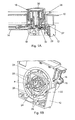
- the rotary dial of the embodiment is used, for example, as a control within a control panel 10 of a home electronic appliance such as a washing machine, a tumble dryer, a dishwasher, a microwave oven, a cooker, and the like, without being limited to these applications.
- a control panel 10 Behind the control panel 10 is a housing 12 for receiving an electronic control of the electronic household appliance including a circuit board 14 with corresponding components.
- the main components of the rotary selector are a control panel 16 which protrudes through a recess in the control panel 10 from this and is rotatably mounted, an adapter 18 which is rotatably connected to the control panel 16, and a spring element 22.
- the rotational position of the control panel 16 and of the adapter 18 can be detected, for example, via a rotary position sensor 29 (eg, magnetic sensor with Hall elements) and evaluated by the electronic control to implement the manipulated variable desired by the user.
- a rotary position sensor 29 eg, magnetic sensor with Hall elements
- the present invention is not limited to this type of detecting the rotational position of the rotary selector and may alternatively be designed so that the rotation of the adapter 18 is transferable to an actuator of the electronic control (see later described second embodiment).
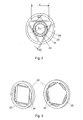
- the adapter 18 of the rotary selector is formed in its lower end portion with a latch portion 19 provided with a predetermined number (six in this embodiment) of circumferentially uniformly arranged and formed side surfaces 20 (see Fig. 1B ).
- the side surfaces 20 are formed substantially flat and straight.
- the adapter 18 with its latching portion 19 is rotated together with the control panel 16 (arrow a), since the two elements are rotatably connected to each other (eg connector).
- the spring element 22 which is arranged in a stationary manner and can advantageously be molded onto the housing 12 with a corresponding material selection, so that the number of components and thus also the assembly effort are reduced, is arranged coaxially with the adapter 18 of the rotary selector.
- the spring element 22 has a predetermined number (three in this embodiment) of elastic webs 24 which are arranged and formed uniformly in the circumferential direction of the latching portion 19.
- the elastic webs 24 are substantially rectilinear and extend tangentially to the side surfaces 20 of the latching portion 19, so that the elastic webs 24 of the spring element 22 can come into surface contact with the side surfaces 20 of the latching portion 19 of the adapter 18, as in the rotational position of Fig. 1 B indicated.
- the number of side surfaces 20 of the latching portion 19 is an integer multiple of the number of elastic webs 24 of the spring element 2.
- the elastic webs 24 of the spring element 22 are preferably connected to each other via a connecting ring 25 which is formed integrally with the elastic webs and of the same material as these.
- the spring element 22 is a one-piece component.
- Fig. 1 B on the housing 12 supports 26 are formed, which support the elastic webs 24 of the spring element 22 respectively at both ends thereof on both sides. As a result, the stability of the spring element 22 is increased and promoted the return of the elastic webs 24 in their initial position.
- the spring element 22 is preferably formed of a plastic material (e.g., POM) so as to dampen the detent sounds of the rotary selector.
- POM plastic material
- the following materials can be used: for the control panel 16 and the panel insert 28, for example, ABS plastic, for the adapter 18, for example, PET or PA and for the housing 12, for example, PC + ABS-FR.
- the present invention is not limited to the materials specified herein.
- the rotary selector thus constructed offers the user a more pleasant locking behavior than the previous solutions of the prior art.
- the locking noise are attenuated when the spring element 22 is formed of a suitable plastic.
- the reliability and durability of the rotary selector are improved.
- the diameter d of the latching portion 19 of the adapter 18 is for example 25.80 mm. In this case, the diameter d is measured relative to the envelope at the outer edges of the adapter 18 between the individual side surfaces 20.
- the free length I of the three elastic web elements 24 is for example 30.0 mm and the thickness h of the elastic webs 24 is for example 1, 6 mm.
- the maximum distance between the side surfaces 20 of the locking portion 19 and said envelope is 0.80 mm, this distance at the same time means the deflection s of the elastic webs 24 during rotation of the control element 16 and the adapter 19.
- the rotary selector with the spring element 22 with three elastic webs 24 provides a total of six locked rotational positions corresponding to the number of side surfaces 20 of the locking portion 19.
- the spring element is accordingly formed with four (diamond spring), five (pentagonal spring) or more elastic webs 24 which are connected to each other via the connecting ring 25. It should only be noted that the number of side surfaces 20 of the latching portion 19 must always be an integer multiple of the number of elastic webs 24 of the spring element 22.
- the rotary knob is further provided with a screen insert 28 which is arranged coaxially to the control panel 16 in the control panel 10 and serves as an information carrier.
- the bezel insert 28 contains information for the user regarding the functionality of the rotary selector (program selection, power selection, etc.) and / or the manipulated variables corresponding to the individual rotary positions (eg washing program, power level, etc.) for the electronic control.
- FIGS. 1A and 1B to recognize that the control panel 16 and the adapter 18 are formed as a hollow cylinder.
- a control part 30 of the push button is arranged coaxially and centrally to the control element 16 of the rotary selector, and an adapter 32 of the push button is arranged coaxially and in the middle of the adapter 18 of the rotary selector.
- the pushbutton acts on a corresponding switch 39 (see Fig. 4A ) disposed on the board 14.
- the operating part 30 of the pushbutton may, for example, be made of ABS plastic, while the adapter 32 of the pushbutton is formed, for example, of POM.
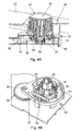
- FIGS. 4A and 4B a second embodiment of a rotary selector will be described in more detail below.
- the rotary selector of the second embodiment differs from the first embodiment in the manner of detecting the rotation of the operating member 16 to the electronic controller.
- a potentiometer 37 is provided as a possible actuator on the circuit board 14 in this case.
- the adapter 18 of the rotary selector is formed for this purpose at its lower end with a gear 34 which is in engagement with a gear 36 for driving the potentiometer 37.
- the gear 36 is mounted in an advantageous manner via a bearing point 38 which is integrally provided on the spring element 22. As in particular in Fig. 4B can be seen, this is the connecting ring 25 of the spring element 22 on the potentiometer 37 side facing extended.
Landscapes
- Physics & Mathematics (AREA)
- General Physics & Mathematics (AREA)
- Engineering & Computer Science (AREA)
- Automation & Control Theory (AREA)
- Rotary Switch, Piano Key Switch, And Lever Switch (AREA)
- Detail Structures Of Washing Machines And Dryers (AREA)
- Mechanical Control Devices (AREA)
- Main Body Construction Of Washing Machines And Laundry Dryers (AREA)
- Selective Calling Equipment (AREA)
- Mechanisms For Operating Contacts (AREA)
Applications Claiming Priority (1)
| Application Number | Priority Date | Filing Date | Title |
|---|---|---|---|
| DE102007037965A DE102007037965A1 (de) | 2007-08-11 | 2007-08-11 | Drehwähler |
Publications (3)
| Publication Number | Publication Date |
|---|---|
| EP2026366A2 true EP2026366A2 (fr) | 2009-02-18 |
| EP2026366A3 EP2026366A3 (fr) | 2009-12-16 |
| EP2026366B1 EP2026366B1 (fr) | 2016-05-25 |
Family
ID=39926632
Family Applications (1)
| Application Number | Title | Priority Date | Filing Date |
|---|---|---|---|
| EP08013968.6A Not-in-force EP2026366B1 (fr) | 2007-08-11 | 2008-08-05 | Sélecteur rotatif |
Country Status (5)
| Country | Link |
|---|---|
| US (1) | US7987738B2 (fr) |
| EP (1) | EP2026366B1 (fr) |
| CN (1) | CN101364496B (fr) |
| DE (1) | DE102007037965A1 (fr) |
| PL (1) | PL2026366T3 (fr) |
Cited By (1)
| Publication number | Priority date | Publication date | Assignee | Title |
|---|---|---|---|---|
| WO2012084627A1 (fr) * | 2010-12-22 | 2012-06-28 | BSH Bosch und Siemens Hausgeräte GmbH | Appareil électroménager comportant un bandeau de commande |
Families Citing this family (17)
| Publication number | Priority date | Publication date | Assignee | Title |
|---|---|---|---|---|
| US5915380A (en) | 1997-03-14 | 1999-06-29 | Nellcor Puritan Bennett Incorporated | System and method for controlling the start up of a patient ventilator |
| US8021310B2 (en) | 2006-04-21 | 2011-09-20 | Nellcor Puritan Bennett Llc | Work of breathing display for a ventilation system |
| US7784461B2 (en) | 2006-09-26 | 2010-08-31 | Nellcor Puritan Bennett Llc | Three-dimensional waveform display for a breathing assistance system |
| US9119925B2 (en) | 2009-12-04 | 2015-09-01 | Covidien Lp | Quick initiation of respiratory support via a ventilator user interface |
| US8335992B2 (en) * | 2009-12-04 | 2012-12-18 | Nellcor Puritan Bennett Llc | Visual indication of settings changes on a ventilator graphical user interface |
| US8924878B2 (en) | 2009-12-04 | 2014-12-30 | Covidien Lp | Display and access to settings on a ventilator graphical user interface |
| US9262588B2 (en) | 2009-12-18 | 2016-02-16 | Covidien Lp | Display of respiratory data graphs on a ventilator graphical user interface |
| US8499252B2 (en) | 2009-12-18 | 2013-07-30 | Covidien Lp | Display of respiratory data graphs on a ventilator graphical user interface |
| US8415577B2 (en) * | 2010-06-18 | 2013-04-09 | Motorola Solutions, Inc. | Assembly for increasing torque tactility of a rotary control for a handheld radio |
| US9105419B2 (en) | 2011-11-18 | 2015-08-11 | Motorola Solutions, Inc. | Plunger mechanism for switch applications |
| US10362967B2 (en) | 2012-07-09 | 2019-07-30 | Covidien Lp | Systems and methods for missed breath detection and indication |
| US9268356B2 (en) | 2013-03-15 | 2016-02-23 | Touchsensor Technologies, Llc | Modular knob system |
| US9950129B2 (en) | 2014-10-27 | 2018-04-24 | Covidien Lp | Ventilation triggering using change-point detection |
| RU2702403C1 (ru) | 2015-09-25 | 2019-10-08 | Эссити Хайджин Энд Хелт Актиеболаг | Насос с полимерной пружиной |
| MX2018003521A (es) | 2015-09-25 | 2018-09-11 | Sca Hygiene Prod Ab | Bomba para distribucion de fluidos. |
| EP3600687B1 (fr) | 2017-03-29 | 2023-01-25 | Essity Hygiene and Health Aktiebolag | Ressort plastomère à soupape captive |
| US11672934B2 (en) | 2020-05-12 | 2023-06-13 | Covidien Lp | Remote ventilator adjustment |
Family Cites Families (12)
| Publication number | Priority date | Publication date | Assignee | Title |
|---|---|---|---|---|
| US2854855A (en) * | 1956-03-20 | 1958-10-07 | Altofer Bros Company | Control timer |
| US3196237A (en) * | 1962-07-11 | 1965-07-20 | Ark Les Switch Corp | Rotary switch using plastic cover with integral leaf springs as positioning means |
| DE1219560B (de) * | 1962-07-24 | 1966-06-23 | Rau Swf Autozubehoer | Schalter |
| US3260805A (en) * | 1964-06-19 | 1966-07-12 | Miniature Elect Components | Rotary switch with detent |
| US3843186A (en) * | 1971-04-19 | 1974-10-22 | Interproduct Nv | Hoist clamp |
| EP0359070B1 (fr) * | 1988-09-12 | 1995-01-11 | Grässlin Kg | Dispositif pour régler le temps d'un interrupteur horaire |
| DE4430018A1 (de) * | 1994-08-24 | 1996-02-29 | Siemens Ag | Elektrische Stelleinrichtung |
| US5589671A (en) * | 1995-08-22 | 1996-12-31 | Us Controls Corp. | Rotary switch with spring stabilized contact control rotor |
| DE19832678A1 (de) * | 1998-07-21 | 2000-02-10 | Mannesmann Vdo Ag | Schaltungsanordnung mit einem Drehgeber |
| US6374696B1 (en) | 1999-12-17 | 2002-04-23 | Trw Inc. | Detent assembly |
| GB2372151A (en) * | 2001-02-09 | 2002-08-14 | Arcolectric Switches Plc | Switch assembly |
| TWM249054U (en) * | 2004-01-06 | 2004-11-01 | Benq Corp | Dial structure |
-
2007
- 2007-08-11 DE DE102007037965A patent/DE102007037965A1/de not_active Withdrawn
-
2008
- 2008-07-23 CN CN2008101341563A patent/CN101364496B/zh not_active Expired - Fee Related
- 2008-07-29 US US12/181,763 patent/US7987738B2/en not_active Expired - Fee Related
- 2008-08-05 EP EP08013968.6A patent/EP2026366B1/fr not_active Not-in-force
- 2008-08-05 PL PL08013968.6T patent/PL2026366T3/pl unknown
Cited By (1)
| Publication number | Priority date | Publication date | Assignee | Title |
|---|---|---|---|---|
| WO2012084627A1 (fr) * | 2010-12-22 | 2012-06-28 | BSH Bosch und Siemens Hausgeräte GmbH | Appareil électroménager comportant un bandeau de commande |
Also Published As
| Publication number | Publication date |
|---|---|
| US20090038921A1 (en) | 2009-02-12 |
| PL2026366T3 (pl) | 2016-11-30 |
| EP2026366B1 (fr) | 2016-05-25 |
| DE102007037965A1 (de) | 2009-02-19 |
| EP2026366A3 (fr) | 2009-12-16 |
| US7987738B2 (en) | 2011-08-02 |
| CN101364496A (zh) | 2009-02-11 |
| CN101364496B (zh) | 2012-11-14 |
Similar Documents
| Publication | Publication Date | Title |
|---|---|---|
| EP2026366B1 (fr) | Sélecteur rotatif | |
| EP2457002B1 (fr) | Dispositif de detection de la position d'un levier de changement et/ou de selection de vitesses pour une boite de vitesses et dispositif de commande pour la boite de vitesses d'un vehicule automobile | |
| DE10323544B4 (de) | Rasteinrichtung für ein dreheinstellbares, elektrisches Bauelement | |
| DE10234925A1 (de) | Drehwähler | |
| EP0609672A2 (fr) | Interrupteur de sécurité | |
| EP3441224B1 (fr) | Système de roue dentée et dispositif capteur | |
| DE102016223018B4 (de) | Getriebezahnradbetätigungseinrichtung für ein doppelkupplungsgetriebe | |
| WO2016012243A1 (fr) | Unité de commande pour appareil électrique, en particulier pour composant de véhicule | |
| DE102008021829A1 (de) | Drehmomentstütze zur Befestigung des Gehäuses eines Drehgebers an einem Elektromotor | |
| DE19947529B4 (de) | Inkrementelle Codiervorrichtung mit einer Druckknopffunktion | |
| DE102017003246A1 (de) | Bedienvorrichtung mit druckempfindlichem Tastschalter | |
| EP1138544A2 (fr) | Elément de commande multi-fonction | |
| DE112019004327T5 (de) | Zahnradschaltstruktur einer elektroausrüstung und elektrisch angetriebenes werkzeug diese struktur umfassend | |
| DE102009058541A1 (de) | Schaltarretierung | |
| DE102014116827B4 (de) | Doppelwellenencoder | |
| EP2348638A2 (fr) | Commutateur de contact et/ou de rapprochement capacitif | |
| DE102009002724A1 (de) | Drehbarer Betätigungsmechanismus mit wählbaren Drehrädern | |
| DE102024102583A1 (de) | Bedieneinheit für ein Fahrzeug | |
| DE69700101T2 (de) | Drucktasteneinrichtung | |
| DE3140772C2 (de) | Stufendrehschalter | |
| DE2636920A1 (de) | Rastvorrichtung | |
| EP0337927B1 (fr) | Commutateur de gamme, en particulier pour un relais temporisé | |
| DE102015104888B4 (de) | Anordnung eines Magnetelements mit Lagesensor zur Positionserkennung an einem rotierbaren Maschinenelement | |
| EP3837708B1 (fr) | Commutateur électrique | |
| WO2011141262A1 (fr) | Dispositif de commande pour un appareil ménager ainsi qu'appareil ménager pourvu d'un dispositif de commande |
Legal Events
| Date | Code | Title | Description |
|---|---|---|---|
| PUAI | Public reference made under article 153(3) epc to a published international application that has entered the european phase |
Free format text: ORIGINAL CODE: 0009012 |
|
| AK | Designated contracting states |
Kind code of ref document: A2 Designated state(s): AT BE BG CH CY CZ DE DK EE ES FI FR GB GR HR HU IE IS IT LI LT LU LV MC MT NL NO PL PT RO SE SI SK TR |
|
| AX | Request for extension of the european patent |
Extension state: AL BA MK RS |
|
| PUAL | Search report despatched |
Free format text: ORIGINAL CODE: 0009013 |
|
| AK | Designated contracting states |
Kind code of ref document: A3 Designated state(s): AT BE BG CH CY CZ DE DK EE ES FI FR GB GR HR HU IE IS IT LI LT LU LV MC MT NL NO PL PT RO SE SI SK TR |
|
| AX | Request for extension of the european patent |
Extension state: AL BA MK RS |
|
| 17P | Request for examination filed |
Effective date: 20091217 |
|
| 17Q | First examination report despatched |
Effective date: 20100128 |
|
| AKX | Designation fees paid |
Designated state(s): AT BE BG CH CY CZ DE DK EE ES FI FR GB GR HR HU IE IS IT LI LT LU LV MC MT NL NO PL PT RO SE SI SK TR |
|
| GRAP | Despatch of communication of intention to grant a patent |
Free format text: ORIGINAL CODE: EPIDOSNIGR1 |
|
| INTG | Intention to grant announced |
Effective date: 20160112 |
|
| GRAS | Grant fee paid |
Free format text: ORIGINAL CODE: EPIDOSNIGR3 |
|
| GRAA | (expected) grant |
Free format text: ORIGINAL CODE: 0009210 |
|
| AK | Designated contracting states |
Kind code of ref document: B1 Designated state(s): AT BE BG CH CY CZ DE DK EE ES FI FR GB GR HR HU IE IS IT LI LT LU LV MC MT NL NO PL PT RO SE SI SK TR |
|
| REG | Reference to a national code |
Ref country code: GB Ref legal event code: FG4D Free format text: NOT ENGLISH |
|
| REG | Reference to a national code |
Ref country code: CH Ref legal event code: EP |
|
| REG | Reference to a national code |
Ref country code: IE Ref legal event code: FG4D Free format text: LANGUAGE OF EP DOCUMENT: GERMAN Ref country code: AT Ref legal event code: REF Ref document number: 802928 Country of ref document: AT Kind code of ref document: T Effective date: 20160615 |
|
| REG | Reference to a national code |
Ref country code: DE Ref legal event code: R096 Ref document number: 502008014237 Country of ref document: DE |
|
| REG | Reference to a national code |
Ref country code: LT Ref legal event code: MG4D |
|
| REG | Reference to a national code |
Ref country code: NL Ref legal event code: MP Effective date: 20160525 |
|
| PG25 | Lapsed in a contracting state [announced via postgrant information from national office to epo] |
Ref country code: LT Free format text: LAPSE BECAUSE OF FAILURE TO SUBMIT A TRANSLATION OF THE DESCRIPTION OR TO PAY THE FEE WITHIN THE PRESCRIBED TIME-LIMIT Effective date: 20160525 Ref country code: FI Free format text: LAPSE BECAUSE OF FAILURE TO SUBMIT A TRANSLATION OF THE DESCRIPTION OR TO PAY THE FEE WITHIN THE PRESCRIBED TIME-LIMIT Effective date: 20160525 Ref country code: NL Free format text: LAPSE BECAUSE OF FAILURE TO SUBMIT A TRANSLATION OF THE DESCRIPTION OR TO PAY THE FEE WITHIN THE PRESCRIBED TIME-LIMIT Effective date: 20160525 Ref country code: NO Free format text: LAPSE BECAUSE OF FAILURE TO SUBMIT A TRANSLATION OF THE DESCRIPTION OR TO PAY THE FEE WITHIN THE PRESCRIBED TIME-LIMIT Effective date: 20160825 |
|
| PG25 | Lapsed in a contracting state [announced via postgrant information from national office to epo] |
Ref country code: SE Free format text: LAPSE BECAUSE OF FAILURE TO SUBMIT A TRANSLATION OF THE DESCRIPTION OR TO PAY THE FEE WITHIN THE PRESCRIBED TIME-LIMIT Effective date: 20160525 Ref country code: PT Free format text: LAPSE BECAUSE OF FAILURE TO SUBMIT A TRANSLATION OF THE DESCRIPTION OR TO PAY THE FEE WITHIN THE PRESCRIBED TIME-LIMIT Effective date: 20160926 Ref country code: ES Free format text: LAPSE BECAUSE OF FAILURE TO SUBMIT A TRANSLATION OF THE DESCRIPTION OR TO PAY THE FEE WITHIN THE PRESCRIBED TIME-LIMIT Effective date: 20160525 Ref country code: HR Free format text: LAPSE BECAUSE OF FAILURE TO SUBMIT A TRANSLATION OF THE DESCRIPTION OR TO PAY THE FEE WITHIN THE PRESCRIBED TIME-LIMIT Effective date: 20160525 Ref country code: GR Free format text: LAPSE BECAUSE OF FAILURE TO SUBMIT A TRANSLATION OF THE DESCRIPTION OR TO PAY THE FEE WITHIN THE PRESCRIBED TIME-LIMIT Effective date: 20160826 Ref country code: LV Free format text: LAPSE BECAUSE OF FAILURE TO SUBMIT A TRANSLATION OF THE DESCRIPTION OR TO PAY THE FEE WITHIN THE PRESCRIBED TIME-LIMIT Effective date: 20160525 |
|
| PG25 | Lapsed in a contracting state [announced via postgrant information from national office to epo] |
Ref country code: IT Free format text: LAPSE BECAUSE OF FAILURE TO SUBMIT A TRANSLATION OF THE DESCRIPTION OR TO PAY THE FEE WITHIN THE PRESCRIBED TIME-LIMIT Effective date: 20160525 Ref country code: BE Free format text: LAPSE BECAUSE OF NON-PAYMENT OF DUE FEES Effective date: 20160831 |
|
| PG25 | Lapsed in a contracting state [announced via postgrant information from national office to epo] |
Ref country code: CZ Free format text: LAPSE BECAUSE OF FAILURE TO SUBMIT A TRANSLATION OF THE DESCRIPTION OR TO PAY THE FEE WITHIN THE PRESCRIBED TIME-LIMIT Effective date: 20160525 Ref country code: DK Free format text: LAPSE BECAUSE OF FAILURE TO SUBMIT A TRANSLATION OF THE DESCRIPTION OR TO PAY THE FEE WITHIN THE PRESCRIBED TIME-LIMIT Effective date: 20160525 Ref country code: EE Free format text: LAPSE BECAUSE OF FAILURE TO SUBMIT A TRANSLATION OF THE DESCRIPTION OR TO PAY THE FEE WITHIN THE PRESCRIBED TIME-LIMIT Effective date: 20160525 Ref country code: SK Free format text: LAPSE BECAUSE OF FAILURE TO SUBMIT A TRANSLATION OF THE DESCRIPTION OR TO PAY THE FEE WITHIN THE PRESCRIBED TIME-LIMIT Effective date: 20160525 Ref country code: RO Free format text: LAPSE BECAUSE OF FAILURE TO SUBMIT A TRANSLATION OF THE DESCRIPTION OR TO PAY THE FEE WITHIN THE PRESCRIBED TIME-LIMIT Effective date: 20160525 |
|
| REG | Reference to a national code |
Ref country code: DE Ref legal event code: R097 Ref document number: 502008014237 Country of ref document: DE |
|
| PG25 | Lapsed in a contracting state [announced via postgrant information from national office to epo] |
Ref country code: MC Free format text: LAPSE BECAUSE OF FAILURE TO SUBMIT A TRANSLATION OF THE DESCRIPTION OR TO PAY THE FEE WITHIN THE PRESCRIBED TIME-LIMIT Effective date: 20160525 |
|
| PLBE | No opposition filed within time limit |
Free format text: ORIGINAL CODE: 0009261 |
|
| REG | Reference to a national code |
Ref country code: CH Ref legal event code: PL |
|
| STAA | Information on the status of an ep patent application or granted ep patent |
Free format text: STATUS: NO OPPOSITION FILED WITHIN TIME LIMIT |
|
| GBPC | Gb: european patent ceased through non-payment of renewal fee |
Effective date: 20160825 |
|
| PG25 | Lapsed in a contracting state [announced via postgrant information from national office to epo] |
Ref country code: CH Free format text: LAPSE BECAUSE OF NON-PAYMENT OF DUE FEES Effective date: 20160831 Ref country code: LI Free format text: LAPSE BECAUSE OF NON-PAYMENT OF DUE FEES Effective date: 20160831 |
|
| 26N | No opposition filed |
Effective date: 20170228 |
|
| REG | Reference to a national code |
Ref country code: FR Ref legal event code: ST Effective date: 20170428 |
|
| PG25 | Lapsed in a contracting state [announced via postgrant information from national office to epo] |
Ref country code: SI Free format text: LAPSE BECAUSE OF FAILURE TO SUBMIT A TRANSLATION OF THE DESCRIPTION OR TO PAY THE FEE WITHIN THE PRESCRIBED TIME-LIMIT Effective date: 20160525 |
|
| REG | Reference to a national code |
Ref country code: IE Ref legal event code: MM4A |
|
| PG25 | Lapsed in a contracting state [announced via postgrant information from national office to epo] |
Ref country code: IE Free format text: LAPSE BECAUSE OF NON-PAYMENT OF DUE FEES Effective date: 20160805 Ref country code: GB Free format text: LAPSE BECAUSE OF NON-PAYMENT OF DUE FEES Effective date: 20160825 Ref country code: FR Free format text: LAPSE BECAUSE OF NON-PAYMENT OF DUE FEES Effective date: 20160831 |
|
| PG25 | Lapsed in a contracting state [announced via postgrant information from national office to epo] |
Ref country code: LU Free format text: LAPSE BECAUSE OF NON-PAYMENT OF DUE FEES Effective date: 20160805 |
|
| REG | Reference to a national code |
Ref country code: AT Ref legal event code: MM01 Ref document number: 802928 Country of ref document: AT Kind code of ref document: T Effective date: 20160805 |
|
| PG25 | Lapsed in a contracting state [announced via postgrant information from national office to epo] |
Ref country code: AT Free format text: LAPSE BECAUSE OF NON-PAYMENT OF DUE FEES Effective date: 20160805 |
|
| PG25 | Lapsed in a contracting state [announced via postgrant information from national office to epo] |
Ref country code: CY Free format text: LAPSE BECAUSE OF FAILURE TO SUBMIT A TRANSLATION OF THE DESCRIPTION OR TO PAY THE FEE WITHIN THE PRESCRIBED TIME-LIMIT Effective date: 20160525 Ref country code: HU Free format text: LAPSE BECAUSE OF FAILURE TO SUBMIT A TRANSLATION OF THE DESCRIPTION OR TO PAY THE FEE WITHIN THE PRESCRIBED TIME-LIMIT; INVALID AB INITIO Effective date: 20080805 |
|
| PG25 | Lapsed in a contracting state [announced via postgrant information from national office to epo] |
Ref country code: TR Free format text: LAPSE BECAUSE OF FAILURE TO SUBMIT A TRANSLATION OF THE DESCRIPTION OR TO PAY THE FEE WITHIN THE PRESCRIBED TIME-LIMIT Effective date: 20160525 Ref country code: MT Free format text: LAPSE BECAUSE OF FAILURE TO SUBMIT A TRANSLATION OF THE DESCRIPTION OR TO PAY THE FEE WITHIN THE PRESCRIBED TIME-LIMIT Effective date: 20160525 Ref country code: IS Free format text: LAPSE BECAUSE OF FAILURE TO SUBMIT A TRANSLATION OF THE DESCRIPTION OR TO PAY THE FEE WITHIN THE PRESCRIBED TIME-LIMIT Effective date: 20160525 |
|
| PG25 | Lapsed in a contracting state [announced via postgrant information from national office to epo] |
Ref country code: BG Free format text: LAPSE BECAUSE OF FAILURE TO SUBMIT A TRANSLATION OF THE DESCRIPTION OR TO PAY THE FEE WITHIN THE PRESCRIBED TIME-LIMIT Effective date: 20160525 |
|
| PGFP | Annual fee paid to national office [announced via postgrant information from national office to epo] |
Ref country code: PL Payment date: 20200729 Year of fee payment: 13 |
|
| PGFP | Annual fee paid to national office [announced via postgrant information from national office to epo] |
Ref country code: DE Payment date: 20201021 Year of fee payment: 13 |
|
| REG | Reference to a national code |
Ref country code: DE Ref legal event code: R119 Ref document number: 502008014237 Country of ref document: DE |
|
| PG25 | Lapsed in a contracting state [announced via postgrant information from national office to epo] |
Ref country code: DE Free format text: LAPSE BECAUSE OF NON-PAYMENT OF DUE FEES Effective date: 20220301 |
|
| PG25 | Lapsed in a contracting state [announced via postgrant information from national office to epo] |
Ref country code: PL Free format text: LAPSE BECAUSE OF NON-PAYMENT OF DUE FEES Effective date: 20210805 |
|
| PG25 | Lapsed in a contracting state [announced via postgrant information from national office to epo] |
Ref country code: PL Free format text: LAPSE BECAUSE OF NON-PAYMENT OF DUE FEES Effective date: 20210805 |