EP2026401B1 - Herstellungsverfahren eines Sockels für ein Brennstoffzellensystem, sowie durch dieses Verfahren erhaltener Sockel und erhaltenes System - Google Patents
Herstellungsverfahren eines Sockels für ein Brennstoffzellensystem, sowie durch dieses Verfahren erhaltener Sockel und erhaltenes System Download PDFInfo
- Publication number
- EP2026401B1 EP2026401B1 EP08305436A EP08305436A EP2026401B1 EP 2026401 B1 EP2026401 B1 EP 2026401B1 EP 08305436 A EP08305436 A EP 08305436A EP 08305436 A EP08305436 A EP 08305436A EP 2026401 B1 EP2026401 B1 EP 2026401B1
- Authority
- EP
- European Patent Office
- Prior art keywords
- parison
- fuel cell
- end piece
- cavity
- mould
- Prior art date
- Legal status (The legal status is an assumption and is not a legal conclusion. Google has not performed a legal analysis and makes no representation as to the accuracy of the status listed.)
- Active
Links
Images


Classifications
-
- B—PERFORMING OPERATIONS; TRANSPORTING
- B29—WORKING OF PLASTICS; WORKING OF SUBSTANCES IN A PLASTIC STATE IN GENERAL
- B29C—SHAPING OR JOINING OF PLASTICS; SHAPING OF MATERIAL IN A PLASTIC STATE, NOT OTHERWISE PROVIDED FOR; AFTER-TREATMENT OF THE SHAPED PRODUCTS, e.g. REPAIRING
- B29C49/00—Blow-moulding, i.e. blowing a preform or parison to a desired shape within a mould; Apparatus therefor
- B29C49/02—Combined blow-moulding and manufacture of the preform or the parison
- B29C49/04—Extrusion blow-moulding
-
- H—ELECTRICITY
- H01—ELECTRIC ELEMENTS
- H01M—PROCESSES OR MEANS, e.g. BATTERIES, FOR THE DIRECT CONVERSION OF CHEMICAL ENERGY INTO ELECTRICAL ENERGY
- H01M8/00—Fuel cells; Manufacture thereof
- H01M8/24—Grouping of fuel cells, e.g. stacking of fuel cells
- H01M8/2465—Details of groupings of fuel cells
- H01M8/2484—Details of groupings of fuel cells characterised by external manifolds
-
- H—ELECTRICITY
- H01—ELECTRIC ELEMENTS
- H01M—PROCESSES OR MEANS, e.g. BATTERIES, FOR THE DIRECT CONVERSION OF CHEMICAL ENERGY INTO ELECTRICAL ENERGY
- H01M8/00—Fuel cells; Manufacture thereof
- H01M8/10—Fuel cells with solid electrolytes
- H01M2008/1095—Fuel cells with polymeric electrolytes
-
- Y—GENERAL TAGGING OF NEW TECHNOLOGICAL DEVELOPMENTS; GENERAL TAGGING OF CROSS-SECTIONAL TECHNOLOGIES SPANNING OVER SEVERAL SECTIONS OF THE IPC; TECHNICAL SUBJECTS COVERED BY FORMER USPC CROSS-REFERENCE ART COLLECTIONS [XRACs] AND DIGESTS
- Y02—TECHNOLOGIES OR APPLICATIONS FOR MITIGATION OR ADAPTATION AGAINST CLIMATE CHANGE
- Y02E—REDUCTION OF GREENHOUSE GAS [GHG] EMISSIONS, RELATED TO ENERGY GENERATION, TRANSMISSION OR DISTRIBUTION
- Y02E60/00—Enabling technologies; Technologies with a potential or indirect contribution to GHG emissions mitigation
- Y02E60/30—Hydrogen technology
- Y02E60/50—Fuel cells
-
- Y—GENERAL TAGGING OF NEW TECHNOLOGICAL DEVELOPMENTS; GENERAL TAGGING OF CROSS-SECTIONAL TECHNOLOGIES SPANNING OVER SEVERAL SECTIONS OF THE IPC; TECHNICAL SUBJECTS COVERED BY FORMER USPC CROSS-REFERENCE ART COLLECTIONS [XRACs] AND DIGESTS
- Y02—TECHNOLOGIES OR APPLICATIONS FOR MITIGATION OR ADAPTATION AGAINST CLIMATE CHANGE
- Y02P—CLIMATE CHANGE MITIGATION TECHNOLOGIES IN THE PRODUCTION OR PROCESSING OF GOODS
- Y02P70/00—Climate change mitigation technologies in the production process for final industrial or consumer products
- Y02P70/50—Manufacturing or production processes characterised by the final manufactured product
Definitions
- the present invention relates to methods of manufacturing bases for fuel cell systems, to the bases and systems obtained by such manufacturing processes.
- the invention relates to a method of manufacturing bases for fuel cell systems.
- a fuel cell system comprises a fuel cell unit, which comprises a cathode compartment, in which the oxygen of the air is reduced, with production of water, as well as an anode compartment, where produces the oxidation of hydrogen.
- An ion exchange membrane physically separates the cathode and anode compartments, while the latter are connected by an external electrical circuit.
- the cathode compartment is provided with an air supply duct, as well as a duct for evacuating this oxygen-depleted air, mixed with water.
- the anode compartment is placed in communication with a hydrogen supply line, as well as a line for evacuating the hydrogen consumed.
- the latter is mixed with a fraction of water, which has been produced at the cathode and passed through the separation membrane. Nitrogen, having diffused through this membrane, is also mixed with hydrogen, as well as any impurities initially present in the hydrogen. These fluids flow between the fuel cell block and one or more fluid bases of the system, whose function is, inter alia, to ensure this circulation in the whole system.
- the at least two ducts (or channels) sealed with respect to each other with respect to the fluid and the intermediate zone form a single piece. That is to say that the at least two conduits "closed” and the intermediate zone are formed of a single piece and do not require a first molded part cooperating with a separate additional cover (to close said ducts).
- the invention relates to a fuel cell system comprising a fuel cell and a fluid base comprising at least two conduits separated from each other in a gas-tight manner by an intermediate zone obtained by joining in a mold of two opposite walls of an extruded parison, the ducts and the intermediate zone forming a single piece, characterized in that the base further comprises a tip made of a material having the same melting point as the material of the parison, in fluid communication with a conduit, and comprising at least a first end gastightly joined to the conduit by melting material with the parison, and a second end adapted to be fluidly connected to another tip or a battery fuel, the base being fluidly connected to the fuel cell.
- the figure 1 represents an example of a fuel cell system 1 which conventionally comprises one or more cells 2 providing a power supply to a load from fuel flows (for example dihydrogen) and an oxidant (for example air ) in each of the batteries.
- fuel flows for example dihydrogen
- oxidant for example air
- These cells have channels that receive fuel and oxidant and guide them to appropriate anode and cathode regions of the cell. Other channels also guide the fuel and the oxidant not consumed out of the pile.
- other fluids, such as coolants are also likely to flow in each stack.
- the system also comprises a fluid base 3 intended to ensure the circulation of fluids in the batteries 2, as well as in communication with the other elements of the fuel cell system, such as the fuel line 4 (for example a line H 2 ), the humidifier 5 or other.
- a fluid base 3 intended to ensure the circulation of fluids in the batteries 2, as well as in communication with the other elements of the fuel cell system, such as the fuel line 4 (for example a line H 2 ), the humidifier 5 or other.
- the base 3 is made of three distinct parts connected together and to the other system components by channels 6. Some of these channels are shown not connected to the fuel cells on the figure 1 to facilitate the readability of the drawing. These three parts are a base called "bottom" 7, an oxidizer base 8 and a fuel base 9.
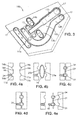
- This mold has a lower half 10a shown in FIG. figure 2 and an upper half 10b complementary shown on the figure 3 .
- the lower half is intended to mold the bottom portion of the base, and the upper half its lid portion.
- the mold defines a set of cavities including a substantially linear main cavity 11a, 11b, a substantially curved main cavity 12a, 12b, and small transverse cavities 13a, 13b, 14a, 14b and 15a, 15b.
- Each cavity can have a profile and / or a variable depth according to the needs of the application.
- the mold further comprises several intermediate zones 16a, 16b of flat surfaces interconnecting the cavities.
- a number of openings 17 are formed in the bottom of the cavities.
- FIGS. 4a-4e represent a fictitious cross-section taken in the mold at an opening 17 of a first cavity (for example the cavity 11b, 11a) and at a portion of a second cavity (for example 14b, 14a) without opening.
- the two cavities are interconnected by a flat intermediate zone 16b, 16a.
- the two mold parts 10a, 10b are located at a distance from one another.
- a fitting 18 is fitted in each of the openings 17 of the upper mold part 10b.
- Such a nozzle comprises at least a first end intended to be connected to the conduits formed in the base, and at least a second end to be fluidly connected to an external component or to another conduit of the base.
- the outer surface of the tip may be shaped to provide reliefs for attachment. This tip is for example previously obtained by molding a thermoplastic part.
- the cylindrical tip is threaded on a striker mandrel 24 movable relative to the mold.
- a plastic parison 19 is extruded into the mold.
- This parison is made of a thermoplastic material, for example having an identical melting point (at about 5 ° C) to the material of the tips. This is for example the same material.
- the parison has internal walls 20a, 20b opposite.
- the mold is closed.
- the walls of the halves 10a and 10b arrive close to the contact, so that the walls 20a, 20b of the parison join at this level, thus forming an intermediate zone 21 of the base 7.
- a hot air is blown, by known means, perpendicularly to the plane of the drawing. This hot air is blown into the parison at each cavity, so as to push the outer walls of the parison into contact with the wall of the mold in each cavity.
- a first fluid conduit 31 is formed in the cavity 11a, 11b and a second fluid conduit 34 in the cavity 14a, 14b, sealed with respect to each other with respect to the fluid via of the intermediate zone 21.
- the deformation causes a variation in the thickness of the parison.
- the latter is minimum in the bottom of the duct.
- the end portions (top and bottom in the figure) of the parison are also contiguous with each other.
- a melting of material takes place in the cavity 11b between the material of the parison 19 and the first end of the endpiece 18.
- the first end of the tip may have a shape specially adapted to merge with the parison.
- the channels used to insufflate the air are closed, for example by crushing material. An intermediate product of the manufacturing process is then obtained.
- the striker mandrel 24 is then actuated so as to create an opening between the conduit 31 and the inside of the nozzle 18.
- This drilling step could alternatively be implemented later during the manufacturing process, by taking over machining for example.
- the mold is opened by separating the two parts of the mold, so as to obtain the fluid base 7 shown in FIG. figure 5 .
- a plurality of endpieces 18a-18o are fluidly connected to respective conduits.
- end pieces 18a-18o setting members 25 such as balls, valves and / or valves, which make it possible to regulate the flow of fluid in the endpiece, for example to implement fluid recirculation as described in WO 03 / 005,472 .
- the end pieces 18a-18o may be used to connect the fluid base to another component of the system, such as for example to another base or to the above-identified components of the fuel cell.
- another component of the system such as for example to another base or to the above-identified components of the fuel cell.
- the end pieces 18i and 181 are interconnected, the end pieces 18k and 18m are connected together, the End caps 18a and 18e are connected to the base H 2 , the end pieces 18n and 18o are connected to the air base, the end pieces 18a-18h being connected to the fuel cells.
- one or more other parts could also be used obtained by the method of embodiment described above.
Landscapes
- Engineering & Computer Science (AREA)
- Manufacturing & Machinery (AREA)
- Mechanical Engineering (AREA)
- Life Sciences & Earth Sciences (AREA)
- Sustainable Development (AREA)
- Sustainable Energy (AREA)
- Chemical & Material Sciences (AREA)
- Chemical Kinetics & Catalysis (AREA)
- Electrochemistry (AREA)
- General Chemical & Material Sciences (AREA)
- Blow-Moulding Or Thermoforming Of Plastics Or The Like (AREA)
- Fuel Cell (AREA)
Claims (8)
- Verfahren zur Herstellung eines Fluidsockels für ein Brennstoffzellensystem, das die folgenden Schritte umfasst:(a) Extrudieren eines Vorformlings (19) aus thermoplastischem Material, der zwei einander gegenüberliegende Wände umfasst;(b) Platzieren des Vorformlings in ein Formwerkzeug (10a, 10b), das eine erste und eine zweite Kavität (11a, 11b, 14a, 14b), die voneinander beabstandet sind, definiert,(c) Schließen des Formwerkzeugs, um in einem Bereich (16a, 16b) des Formwerkzeugs, der zwischen der ersten und der zweiten Kavität liegt, einen Zwischenbereich zu erzeugen, in dem die beiden Wände des Vorformlings gasdicht zusammengefügt sind,(d) Einblasen eines Gases in das Innere des Vorformlings in jede Kavität, um die Wände des Vorformlings an das Formwerkzeug in jeder Kavität zu pressen, um eine Leitung (31, 34) in jeder Kavität zu bilden, und(e) Öffnen des Formwerkzeugs.
- Herstellungsverfahren nach Anspruch 1, bei dem
während des Schritts (b) ein Endstück (18) in einer Kavität des Formwerkzeugs platziert wird,
während des Schritts (d) der Vorformling (19) gasdicht an dem Endstück befestigt wird,
das Verfahren des Weiteren einen Schritt (f) umfasst, während dessen der Vorformling perforiert wird, um einen Fluidsockel zwischen dem Endstück und der in der Kavität gebildeten Leitung zu bilden. - Herstellungsverfahren nach Anspruch 2, wobei- vor Schritt (b) das Endstück (18) geformt wird, und- in dem Endstück ein Perforationsglied befestigt wird, um Schritt (f) durchzuführen.
- Herstellungsverfahren nach Anspruch 2 oder 3, wobei der Vorformling (19) und das Endstück (18) aus Materialien, die den gleichen Schmelzpunkt aufweisen, und vorzugsweise aus dem gleichen Material hergestellt sind.
- Herstellungsverfahren nach einem der Ansprüche 2 bis 4, wobei in einem Endstück (18) ein Ende eines Verbindungsrohrs (26) gasdicht eingepresst wird, wobei das Verbindungsrohr mindestens ein anderes Ende aufweist, das zur Fluidverbindung mit einem anderen Endstück oder einer Brennstoffzelle ausgeführt ist.
- Herstellungsverfahren nach Anspruch 5, wobei in mindestens einem Verbindungsrohr ein Regulierungsglied (25) platziert wird, das zur Regulierung eines Gasdurchflusses in dem Rohr ausgeführt ist.
- Verfahren zur Herstellung eines Fluidsockels für eine Brennstoffzelle, wobei mindestens zwei Teile zusammengefügt werden, die jeweils durch ein Verfahren nach einem der vorhergehenden Ansprüche erhalten werden.
- Brennstoffzellensystem, das eine Brennstoffzelle und einen Fluidsockel mit mindestens zwei Leitungen (31, 34) umfasst, die durch einen Zwischenbereich (21) gasdicht voneinander getrennt sind, der durch Zusammenfügen in einem Formwerkzeug von zwei einander gegenüberliegenden Wänden eines extrudierten Vorformlings erhalten wird, wobei die Leitungen und der Zwischenbereich ein einziges einstückiges Teil bilden, dadurch gekennzeichnet, dass der Sockel des Weiteren ein Endstück (18) umfasst, das aus einem Material hergestellt ist, das den gleichen Schmelzpunkt wie das Material des Vorformlings aufweist, mit einer Leitung in Fluidverbindung steht und mindestens ein erstes Ende, das durch stoffschlüssiges Verbinden mit dem Vorformling gasdicht mit der Leitung verbunden ist, und ein zweites Ende, das zur Fluidverbindung mit einem anderen Endstück oder einer Brennstoffzelle ausgeführt ist, aufweist, wobei der Sockel mit der Brennstoffzelle in Fluidverbindung steht.
Applications Claiming Priority (1)
| Application Number | Priority Date | Filing Date | Title |
|---|---|---|---|
| FR0756962A FR2919964A1 (fr) | 2007-08-06 | 2007-08-06 | Procede de fabrication d'embase pour systeme a pile a combustible, embase et systeme obtenus par un tel procede |
Publications (2)
| Publication Number | Publication Date |
|---|---|
| EP2026401A1 EP2026401A1 (de) | 2009-02-18 |
| EP2026401B1 true EP2026401B1 (de) | 2010-05-26 |
Family
ID=39135357
Family Applications (1)
| Application Number | Title | Priority Date | Filing Date |
|---|---|---|---|
| EP08305436A Active EP2026401B1 (de) | 2007-08-06 | 2008-07-30 | Herstellungsverfahren eines Sockels für ein Brennstoffzellensystem, sowie durch dieses Verfahren erhaltener Sockel und erhaltenes System |
Country Status (7)
| Country | Link |
|---|---|
| US (1) | US7968040B2 (de) |
| EP (1) | EP2026401B1 (de) |
| AT (1) | ATE469446T1 (de) |
| CA (1) | CA2638228A1 (de) |
| DE (1) | DE602008001338D1 (de) |
| ES (1) | ES2346020T3 (de) |
| FR (1) | FR2919964A1 (de) |
Families Citing this family (4)
| Publication number | Priority date | Publication date | Assignee | Title |
|---|---|---|---|---|
| FI123803B (en) | 2012-06-26 | 2013-10-31 | Outotec Oyj | A method for preparing a solvent extraction basin and a solvent extraction basin |
| FI123831B (en) | 2012-06-26 | 2013-11-15 | Outotec Oyj | Solvent extraction clarifier tank arrangement |
| FI124030B (en) * | 2012-06-26 | 2014-02-14 | Outotec Oyj | Method for making a fence and a fence |
| FI123834B (en) | 2012-06-26 | 2013-11-15 | Outotec Oyj | Method of making a trough and trough |
Family Cites Families (10)
| Publication number | Priority date | Publication date | Assignee | Title |
|---|---|---|---|---|
| US4419323A (en) * | 1980-02-08 | 1983-12-06 | Baxter Travenol Laboratories, Inc. | Method for manufacturing a plastic container with non-coring penetrable wall portion |
| US6360560B1 (en) | 1999-12-01 | 2002-03-26 | Visteon Global Technologies, Inc. | Condenser with integral receiver dryer |
| US6541148B1 (en) * | 2000-10-31 | 2003-04-01 | Plug Power Inc. | Manifold system for a fuel cell stack |
| US6543404B2 (en) * | 2001-04-04 | 2003-04-08 | Dow Global Technologies, Inc. | Adhesively bonded engine intake manifold assembly |
| US7108929B2 (en) * | 2003-09-22 | 2006-09-19 | Utc Fuel Cells, Llc | Fuel and air flow control in a multi-stack fuel cell power plant |
| US7323270B2 (en) * | 2004-08-11 | 2008-01-29 | Fuelcell Energy, Inc. | Modular fuel-cell stack assembly |
| US20060060244A1 (en) * | 2004-08-20 | 2006-03-23 | Eggum Shawn D | Fuel cell manifold |
| JP2006221868A (ja) * | 2005-02-08 | 2006-08-24 | Toshiba Corp | 燃料電池 |
| JP2008103241A (ja) | 2006-10-20 | 2008-05-01 | Toyota Motor Corp | 燃料電池 |
| WO2008058165A2 (en) * | 2006-11-06 | 2008-05-15 | Akermin, Inc. | Bioanode and biocathode stack assemblies |
-
2007
- 2007-08-06 FR FR0756962A patent/FR2919964A1/fr active Pending
-
2008
- 2008-07-30 ES ES08305436T patent/ES2346020T3/es active Active
- 2008-07-30 AT AT08305436T patent/ATE469446T1/de not_active IP Right Cessation
- 2008-07-30 EP EP08305436A patent/EP2026401B1/de active Active
- 2008-07-30 DE DE602008001338T patent/DE602008001338D1/de active Active
- 2008-08-04 CA CA002638228A patent/CA2638228A1/fr not_active Abandoned
- 2008-08-04 US US12/185,291 patent/US7968040B2/en not_active Expired - Fee Related
Also Published As
| Publication number | Publication date |
|---|---|
| FR2919964A1 (fr) | 2009-02-13 |
| ATE469446T1 (de) | 2010-06-15 |
| ES2346020T3 (es) | 2010-10-07 |
| US20090104504A1 (en) | 2009-04-23 |
| US7968040B2 (en) | 2011-06-28 |
| DE602008001338D1 (de) | 2010-07-08 |
| EP2026401A1 (de) | 2009-02-18 |
| CA2638228A1 (fr) | 2009-02-06 |
Similar Documents
| Publication | Publication Date | Title |
|---|---|---|
| EP2026401B1 (de) | Herstellungsverfahren eines Sockels für ein Brennstoffzellensystem, sowie durch dieses Verfahren erhaltener Sockel und erhaltenes System | |
| FR2568412A1 (fr) | Perfectionnements aux structures des piles a combustible. | |
| EP3136492B1 (de) | Stapel von elektrochemischen zellen, die in verschiedene gruppen aufgeteilt sind, die ein homogenisierungsfach umfassen | |
| FR2564249A1 (fr) | Amenagements aux structures des piles a combustible | |
| WO2016009154A1 (fr) | Plaque bipolaire pour réacteur électrochimique a zone d'homogénéisation compacte et a faible différentiel de pression | |
| EP2707920B1 (de) | Brennstoffzelle mit verteilern mit individuellen injektordichtungen | |
| EP3245683B1 (de) | Verfahren zur herstellung von dichtungen auf elektrochemischen reaktorkomponenten | |
| EP3235042B1 (de) | Zellstapel einer brennstoffzelle und brennstoffzelle mit solch einem stapel | |
| FR2902930A1 (fr) | Plaque bipolaire pour pile a combustible, et pile a combustible a distribution de fluide amelioree mettant en oeuvre de telles plaques | |
| EP1500445A2 (de) | Grosse Metallform | |
| FR3100984A1 (fr) | Connecteur monobloc pour poche de perfusion souple | |
| FR2807700A1 (fr) | Reservoir a carburant en matiere synthetique et son procede de fabrication | |
| EP2208249B1 (de) | Aufbau einer integrierten brennstoffzelle ohne dichtung | |
| WO2007085735A1 (fr) | Moule de moulage par injection d'une piece comprenant deux portions faites de matieres differentes | |
| WO1994025252A1 (fr) | Electrode de soudage a haute frequence pour poches multicompartiments a usage medical en film plastique, et poches realisees grace a ce materiel | |
| EP2818308B1 (de) | Verfahren zur Herstellung eines Anschlusses | |
| EP2239126B1 (de) | Vakuumformwerkzeug zur Herstellung eines Wellrohres, das hergestelle Rohr und Verfahren | |
| CA2607908C (fr) | Procede pour la fabrication par decomposition en strates d'une piece traversee par des canaux de transfert de fluides prevus dans les interstrates | |
| WO2018011526A1 (fr) | Procede d'impregnation de preforme fibreuse utilisant un joint et procede de fabrication d'une matrice renforcee par une preforme fibreuse | |
| WO2021152234A1 (fr) | Compartiment pour un equipement susceptible de degager de la chaleur | |
| JPH03219551A (ja) | 蓄電池の蓋の製造方法 | |
| FR2552268A1 (fr) | Recipient resistant a la pression pour des elements hybrides electrochimiques alcalins contenant un produit gazeux entrant en reaction, notamment pour des elements metal-hydrogene | |
| FR2799815A1 (fr) | Canalisation et distributeur a air comprime utilisant la canalisation | |
| WO2021014104A1 (fr) | Pile à combustible à membrane polymère électrolyte | |
| FR2800916A1 (fr) | Accumulateur au plomb multicellulaires etanche |
Legal Events
| Date | Code | Title | Description |
|---|---|---|---|
| PUAI | Public reference made under article 153(3) epc to a published international application that has entered the european phase |
Free format text: ORIGINAL CODE: 0009012 |
|
| AK | Designated contracting states |
Kind code of ref document: A1 Designated state(s): AT BE BG CH CY CZ DE DK EE ES FI FR GB GR HR HU IE IS IT LI LT LU LV MC MT NL NO PL PT RO SE SI SK TR |
|
| AX | Request for extension of the european patent |
Extension state: AL BA MK RS |
|
| RIN1 | Information on inventor provided before grant (corrected) |
Inventor name: CLARY, NANCY Inventor name: SIRAC, DENIS Inventor name: ROUSSIN-BOUCHARD, XAVIER |
|
| 17P | Request for examination filed |
Effective date: 20090818 |
|
| 17Q | First examination report despatched |
Effective date: 20090917 |
|
| AKX | Designation fees paid |
Designated state(s): AT BE BG CH CY CZ DE DK EE ES FI FR GB GR HR HU IE IS IT LI LT LU LV MC MT NL NO PL PT RO SE SI SK TR |
|
| AXX | Extension fees paid |
Extension state: BA Payment date: 20090818 Extension state: RS Payment date: 20090818 Extension state: AL Payment date: 20090818 Extension state: MK Payment date: 20090818 |
|
| GRAP | Despatch of communication of intention to grant a patent |
Free format text: ORIGINAL CODE: EPIDOSNIGR1 |
|
| GRAS | Grant fee paid |
Free format text: ORIGINAL CODE: EPIDOSNIGR3 |
|
| GRAA | (expected) grant |
Free format text: ORIGINAL CODE: 0009210 |
|
| AK | Designated contracting states |
Kind code of ref document: B1 Designated state(s): AT BE BG CH CY CZ DE DK EE ES FI FR GB GR HR HU IE IS IT LI LT LU LV MC MT NL NO PL PT RO SE SI SK TR |
|
| AX | Request for extension of the european patent |
Extension state: AL BA MK RS |
|
| REG | Reference to a national code |
Ref country code: GB Ref legal event code: FG4D Free format text: NOT ENGLISH |
|
| REG | Reference to a national code |
Ref country code: CH Ref legal event code: EP |
|
| REG | Reference to a national code |
Ref country code: IE Ref legal event code: FG4D Free format text: LANGUAGE OF EP DOCUMENT: FRENCH |
|
| REF | Corresponds to: |
Ref document number: 602008001338 Country of ref document: DE Date of ref document: 20100708 Kind code of ref document: P |
|
| REG | Reference to a national code |
Ref country code: NL Ref legal event code: VDEP Effective date: 20100526 |
|
| REG | Reference to a national code |
Ref country code: GR Ref legal event code: EP Ref document number: 20100402008 Country of ref document: GR |
|
| REG | Reference to a national code |
Ref country code: ES Ref legal event code: FG2A Ref document number: 2346020 Country of ref document: ES Kind code of ref document: T3 |
|
| LTIE | Lt: invalidation of european patent or patent extension |
Effective date: 20100526 |
|
| PG25 | Lapsed in a contracting state [announced via postgrant information from national office to epo] |
Ref country code: NO Free format text: LAPSE BECAUSE OF FAILURE TO SUBMIT A TRANSLATION OF THE DESCRIPTION OR TO PAY THE FEE WITHIN THE PRESCRIBED TIME-LIMIT Effective date: 20100826 Ref country code: LT Free format text: LAPSE BECAUSE OF FAILURE TO SUBMIT A TRANSLATION OF THE DESCRIPTION OR TO PAY THE FEE WITHIN THE PRESCRIBED TIME-LIMIT Effective date: 20100526 Ref country code: SE Free format text: LAPSE BECAUSE OF FAILURE TO SUBMIT A TRANSLATION OF THE DESCRIPTION OR TO PAY THE FEE WITHIN THE PRESCRIBED TIME-LIMIT Effective date: 20100526 |
|
| PG25 | Lapsed in a contracting state [announced via postgrant information from national office to epo] |
Ref country code: AT Free format text: LAPSE BECAUSE OF FAILURE TO SUBMIT A TRANSLATION OF THE DESCRIPTION OR TO PAY THE FEE WITHIN THE PRESCRIBED TIME-LIMIT Effective date: 20100526 Ref country code: FI Free format text: LAPSE BECAUSE OF FAILURE TO SUBMIT A TRANSLATION OF THE DESCRIPTION OR TO PAY THE FEE WITHIN THE PRESCRIBED TIME-LIMIT Effective date: 20100526 Ref country code: HR Free format text: LAPSE BECAUSE OF FAILURE TO SUBMIT A TRANSLATION OF THE DESCRIPTION OR TO PAY THE FEE WITHIN THE PRESCRIBED TIME-LIMIT Effective date: 20100526 Ref country code: IS Free format text: LAPSE BECAUSE OF FAILURE TO SUBMIT A TRANSLATION OF THE DESCRIPTION OR TO PAY THE FEE WITHIN THE PRESCRIBED TIME-LIMIT Effective date: 20100926 Ref country code: LV Free format text: LAPSE BECAUSE OF FAILURE TO SUBMIT A TRANSLATION OF THE DESCRIPTION OR TO PAY THE FEE WITHIN THE PRESCRIBED TIME-LIMIT Effective date: 20100526 Ref country code: SI Free format text: LAPSE BECAUSE OF FAILURE TO SUBMIT A TRANSLATION OF THE DESCRIPTION OR TO PAY THE FEE WITHIN THE PRESCRIBED TIME-LIMIT Effective date: 20100526 |
|
| PG25 | Lapsed in a contracting state [announced via postgrant information from national office to epo] |
Ref country code: PL Free format text: LAPSE BECAUSE OF FAILURE TO SUBMIT A TRANSLATION OF THE DESCRIPTION OR TO PAY THE FEE WITHIN THE PRESCRIBED TIME-LIMIT Effective date: 20100526 Ref country code: CY Free format text: LAPSE BECAUSE OF FAILURE TO SUBMIT A TRANSLATION OF THE DESCRIPTION OR TO PAY THE FEE WITHIN THE PRESCRIBED TIME-LIMIT Effective date: 20100609 |
|
| REG | Reference to a national code |
Ref country code: IE Ref legal event code: FD4D |
|
| BERE | Be: lapsed |
Owner name: L'AIR LIQUIDE, S.A. POUR L'ETUDE ET L'EXPLOITATIO Effective date: 20100731 |
|
| PG25 | Lapsed in a contracting state [announced via postgrant information from national office to epo] |
Ref country code: DK Free format text: LAPSE BECAUSE OF FAILURE TO SUBMIT A TRANSLATION OF THE DESCRIPTION OR TO PAY THE FEE WITHIN THE PRESCRIBED TIME-LIMIT Effective date: 20100526 Ref country code: IE Free format text: LAPSE BECAUSE OF FAILURE TO SUBMIT A TRANSLATION OF THE DESCRIPTION OR TO PAY THE FEE WITHIN THE PRESCRIBED TIME-LIMIT Effective date: 20100526 Ref country code: NL Free format text: LAPSE BECAUSE OF FAILURE TO SUBMIT A TRANSLATION OF THE DESCRIPTION OR TO PAY THE FEE WITHIN THE PRESCRIBED TIME-LIMIT Effective date: 20100526 Ref country code: EE Free format text: LAPSE BECAUSE OF FAILURE TO SUBMIT A TRANSLATION OF THE DESCRIPTION OR TO PAY THE FEE WITHIN THE PRESCRIBED TIME-LIMIT Effective date: 20100526 |
|
| PG25 | Lapsed in a contracting state [announced via postgrant information from national office to epo] |
Ref country code: CZ Free format text: LAPSE BECAUSE OF FAILURE TO SUBMIT A TRANSLATION OF THE DESCRIPTION OR TO PAY THE FEE WITHIN THE PRESCRIBED TIME-LIMIT Effective date: 20100526 Ref country code: RO Free format text: LAPSE BECAUSE OF FAILURE TO SUBMIT A TRANSLATION OF THE DESCRIPTION OR TO PAY THE FEE WITHIN THE PRESCRIBED TIME-LIMIT Effective date: 20100526 Ref country code: SK Free format text: LAPSE BECAUSE OF FAILURE TO SUBMIT A TRANSLATION OF THE DESCRIPTION OR TO PAY THE FEE WITHIN THE PRESCRIBED TIME-LIMIT Effective date: 20100526 Ref country code: MC Free format text: LAPSE BECAUSE OF NON-PAYMENT OF DUE FEES Effective date: 20100731 |
|
| PLBE | No opposition filed within time limit |
Free format text: ORIGINAL CODE: 0009261 |
|
| STAA | Information on the status of an ep patent application or granted ep patent |
Free format text: STATUS: NO OPPOSITION FILED WITHIN TIME LIMIT |
|
| 26N | No opposition filed |
Effective date: 20110301 |
|
| REG | Reference to a national code |
Ref country code: DE Ref legal event code: R097 Ref document number: 602008001338 Country of ref document: DE Effective date: 20110228 |
|
| PG25 | Lapsed in a contracting state [announced via postgrant information from national office to epo] |
Ref country code: BE Free format text: LAPSE BECAUSE OF NON-PAYMENT OF DUE FEES Effective date: 20100731 |
|
| PG25 | Lapsed in a contracting state [announced via postgrant information from national office to epo] |
Ref country code: MT Free format text: LAPSE BECAUSE OF FAILURE TO SUBMIT A TRANSLATION OF THE DESCRIPTION OR TO PAY THE FEE WITHIN THE PRESCRIBED TIME-LIMIT Effective date: 20100526 |
|
| PG25 | Lapsed in a contracting state [announced via postgrant information from national office to epo] |
Ref country code: LU Free format text: LAPSE BECAUSE OF NON-PAYMENT OF DUE FEES Effective date: 20100730 Ref country code: BG Free format text: LAPSE BECAUSE OF FAILURE TO SUBMIT A TRANSLATION OF THE DESCRIPTION OR TO PAY THE FEE WITHIN THE PRESCRIBED TIME-LIMIT Effective date: 20100526 Ref country code: HU Free format text: LAPSE BECAUSE OF FAILURE TO SUBMIT A TRANSLATION OF THE DESCRIPTION OR TO PAY THE FEE WITHIN THE PRESCRIBED TIME-LIMIT Effective date: 20101127 |
|
| PG25 | Lapsed in a contracting state [announced via postgrant information from national office to epo] |
Ref country code: TR Free format text: LAPSE BECAUSE OF FAILURE TO SUBMIT A TRANSLATION OF THE DESCRIPTION OR TO PAY THE FEE WITHIN THE PRESCRIBED TIME-LIMIT Effective date: 20100526 |
|
| REG | Reference to a national code |
Ref country code: CH Ref legal event code: PL |
|
| PG25 | Lapsed in a contracting state [announced via postgrant information from national office to epo] |
Ref country code: CH Free format text: LAPSE BECAUSE OF NON-PAYMENT OF DUE FEES Effective date: 20120731 Ref country code: LI Free format text: LAPSE BECAUSE OF NON-PAYMENT OF DUE FEES Effective date: 20120731 |
|
| PG25 | Lapsed in a contracting state [announced via postgrant information from national office to epo] |
Ref country code: PT Free format text: LAPSE BECAUSE OF NON-PAYMENT OF DUE FEES Effective date: 20100526 |
|
| PG25 | Lapsed in a contracting state [announced via postgrant information from national office to epo] |
Ref country code: BG Free format text: LAPSE BECAUSE OF FAILURE TO SUBMIT A TRANSLATION OF THE DESCRIPTION OR TO PAY THE FEE WITHIN THE PRESCRIBED TIME-LIMIT Effective date: 20100826 |
|
| REG | Reference to a national code |
Ref country code: FR Ref legal event code: PLFP Year of fee payment: 9 |
|
| REG | Reference to a national code |
Ref country code: FR Ref legal event code: PLFP Year of fee payment: 10 |
|
| PGFP | Annual fee paid to national office [announced via postgrant information from national office to epo] |
Ref country code: FR Payment date: 20170724 Year of fee payment: 10 Ref country code: GB Payment date: 20170719 Year of fee payment: 10 Ref country code: DE Payment date: 20170724 Year of fee payment: 10 Ref country code: IT Payment date: 20170724 Year of fee payment: 10 Ref country code: ES Payment date: 20170825 Year of fee payment: 10 Ref country code: GR Payment date: 20170712 Year of fee payment: 10 |
|
| REG | Reference to a national code |
Ref country code: DE Ref legal event code: R119 Ref document number: 602008001338 Country of ref document: DE |
|
| GBPC | Gb: european patent ceased through non-payment of renewal fee |
Effective date: 20180730 |
|
| PG25 | Lapsed in a contracting state [announced via postgrant information from national office to epo] |
Ref country code: GB Free format text: LAPSE BECAUSE OF NON-PAYMENT OF DUE FEES Effective date: 20180730 Ref country code: FR Free format text: LAPSE BECAUSE OF NON-PAYMENT OF DUE FEES Effective date: 20180731 Ref country code: DE Free format text: LAPSE BECAUSE OF NON-PAYMENT OF DUE FEES Effective date: 20190201 |
|
| PG25 | Lapsed in a contracting state [announced via postgrant information from national office to epo] |
Ref country code: GR Free format text: LAPSE BECAUSE OF NON-PAYMENT OF DUE FEES Effective date: 20190207 |
|
| PG25 | Lapsed in a contracting state [announced via postgrant information from national office to epo] |
Ref country code: IT Free format text: LAPSE BECAUSE OF NON-PAYMENT OF DUE FEES Effective date: 20180730 |
|
| REG | Reference to a national code |
Ref country code: ES Ref legal event code: FD2A Effective date: 20190918 |
|
| PG25 | Lapsed in a contracting state [announced via postgrant information from national office to epo] |
Ref country code: ES Free format text: LAPSE BECAUSE OF NON-PAYMENT OF DUE FEES Effective date: 20180731 |