EP2208249B1 - Aufbau einer integrierten brennstoffzelle ohne dichtung - Google Patents
Aufbau einer integrierten brennstoffzelle ohne dichtung Download PDFInfo
- Publication number
- EP2208249B1 EP2208249B1 EP08842695.2A EP08842695A EP2208249B1 EP 2208249 B1 EP2208249 B1 EP 2208249B1 EP 08842695 A EP08842695 A EP 08842695A EP 2208249 B1 EP2208249 B1 EP 2208249B1
- Authority
- EP
- European Patent Office
- Prior art keywords
- membrane
- assembly
- fluid
- elements
- electrical connection
- Prior art date
- Legal status (The legal status is an assumption and is not a legal conclusion. Google has not performed a legal analysis and makes no representation as to the accuracy of the status listed.)
- Not-in-force
Links
- 239000000446 fuel Substances 0.000 title claims description 24
- 239000012528 membrane Substances 0.000 claims description 54
- 239000012530 fluid Substances 0.000 claims description 27
- 239000004020 conductor Substances 0.000 claims description 24
- 239000000463 material Substances 0.000 claims description 21
- OKTJSMMVPCPJKN-UHFFFAOYSA-N Carbon Chemical compound [C] OKTJSMMVPCPJKN-UHFFFAOYSA-N 0.000 claims description 15
- 238000009826 distribution Methods 0.000 claims description 12
- 229920000642 polymer Polymers 0.000 claims description 12
- 238000000465 moulding Methods 0.000 claims description 9
- 229910021393 carbon nanotube Inorganic materials 0.000 claims description 7
- 239000002041 carbon nanotube Substances 0.000 claims description 7
- 239000002070 nanowire Substances 0.000 claims description 7
- -1 polyethylene Polymers 0.000 claims description 7
- 239000011148 porous material Substances 0.000 claims description 7
- RYGMFSIKBFXOCR-UHFFFAOYSA-N Copper Chemical compound [Cu] RYGMFSIKBFXOCR-UHFFFAOYSA-N 0.000 claims description 6
- 229910052782 aluminium Inorganic materials 0.000 claims description 6
- XAGFODPZIPBFFR-UHFFFAOYSA-N aluminium Chemical compound [Al] XAGFODPZIPBFFR-UHFFFAOYSA-N 0.000 claims description 6
- 229910052799 carbon Inorganic materials 0.000 claims description 6
- 229910052802 copper Inorganic materials 0.000 claims description 6
- 239000010949 copper Substances 0.000 claims description 6
- 229910052751 metal Inorganic materials 0.000 claims description 6
- 239000002184 metal Substances 0.000 claims description 6
- 229920001169 thermoplastic Polymers 0.000 claims description 6
- 229920001940 conductive polymer Polymers 0.000 claims description 5
- 239000004696 Poly ether ether ketone Substances 0.000 claims description 4
- 239000004698 Polyethylene Substances 0.000 claims description 4
- 239000004809 Teflon Substances 0.000 claims description 4
- 229920006362 Teflon® Polymers 0.000 claims description 4
- 239000006229 carbon black Substances 0.000 claims description 4
- 238000004519 manufacturing process Methods 0.000 claims description 4
- 229920002530 polyetherether ketone Polymers 0.000 claims description 4
- 229920000573 polyethylene Polymers 0.000 claims description 4
- 239000004743 Polypropylene Substances 0.000 claims description 3
- 239000004793 Polystyrene Substances 0.000 claims description 3
- 239000002071 nanotube Substances 0.000 claims description 3
- 230000002093 peripheral effect Effects 0.000 claims description 3
- 229920001155 polypropylene Polymers 0.000 claims description 3
- 229920002223 polystyrene Polymers 0.000 claims description 3
- 229920001343 polytetrafluoroethylene Polymers 0.000 claims description 3
- 239000004810 polytetrafluoroethylene Substances 0.000 claims description 3
- 229910052710 silicon Inorganic materials 0.000 claims description 3
- 239000010703 silicon Substances 0.000 claims description 3
- 150000001925 cycloalkenes Chemical class 0.000 claims description 2
- PCHJSUWPFVWCPO-UHFFFAOYSA-N gold Chemical compound [Au] PCHJSUWPFVWCPO-UHFFFAOYSA-N 0.000 claims description 2
- 239000010931 gold Substances 0.000 claims description 2
- 229910052737 gold Inorganic materials 0.000 claims description 2
- 238000009941 weaving Methods 0.000 claims description 2
- 229920000089 Cyclic olefin copolymer Polymers 0.000 claims 2
- 239000004411 aluminium Substances 0.000 claims 2
- 239000000835 fiber Substances 0.000 claims 1
- 239000007789 gas Substances 0.000 description 30
- 238000000034 method Methods 0.000 description 21
- 238000000576 coating method Methods 0.000 description 13
- 239000011248 coating agent Substances 0.000 description 10
- 229910052739 hydrogen Inorganic materials 0.000 description 9
- 239000001257 hydrogen Substances 0.000 description 9
- UFHFLCQGNIYNRP-UHFFFAOYSA-N Hydrogen Chemical compound [H][H] UFHFLCQGNIYNRP-UHFFFAOYSA-N 0.000 description 8
- 238000010438 heat treatment Methods 0.000 description 7
- 238000003466 welding Methods 0.000 description 7
- QVGXLLKOCUKJST-UHFFFAOYSA-N atomic oxygen Chemical compound [O] QVGXLLKOCUKJST-UHFFFAOYSA-N 0.000 description 6
- 238000002347 injection Methods 0.000 description 6
- 239000007924 injection Substances 0.000 description 6
- 229910052760 oxygen Inorganic materials 0.000 description 6
- 239000001301 oxygen Substances 0.000 description 6
- 238000007789 sealing Methods 0.000 description 6
- 238000010586 diagram Methods 0.000 description 5
- 230000000694 effects Effects 0.000 description 5
- 229920000049 Carbon (fiber) Polymers 0.000 description 4
- 239000004917 carbon fiber Substances 0.000 description 4
- XLYOFNOQVPJJNP-UHFFFAOYSA-N water Substances O XLYOFNOQVPJJNP-UHFFFAOYSA-N 0.000 description 4
- 238000004026 adhesive bonding Methods 0.000 description 3
- 238000012423 maintenance Methods 0.000 description 3
- 239000000203 mixture Substances 0.000 description 3
- 239000012778 molding material Substances 0.000 description 3
- XUIMIQQOPSSXEZ-UHFFFAOYSA-N Silicon Chemical compound [Si] XUIMIQQOPSSXEZ-UHFFFAOYSA-N 0.000 description 2
- CSCPPACGZOOCGX-UHFFFAOYSA-N acetone Substances CC(C)=O CSCPPACGZOOCGX-UHFFFAOYSA-N 0.000 description 2
- JUPQTSLXMOCDHR-UHFFFAOYSA-N benzene-1,4-diol;bis(4-fluorophenyl)methanone Chemical compound OC1=CC=C(O)C=C1.C1=CC(F)=CC=C1C(=O)C1=CC=C(F)C=C1 JUPQTSLXMOCDHR-UHFFFAOYSA-N 0.000 description 2
- 238000006243 chemical reaction Methods 0.000 description 2
- 238000013461 design Methods 0.000 description 2
- 229910002804 graphite Inorganic materials 0.000 description 2
- 239000010439 graphite Substances 0.000 description 2
- 238000002844 melting Methods 0.000 description 2
- 230000008018 melting Effects 0.000 description 2
- VNWKTOKETHGBQD-UHFFFAOYSA-N methane Chemical compound C VNWKTOKETHGBQD-UHFFFAOYSA-N 0.000 description 2
- BASFCYQUMIYNBI-UHFFFAOYSA-N platinum Chemical compound [Pt] BASFCYQUMIYNBI-UHFFFAOYSA-N 0.000 description 2
- 239000000243 solution Substances 0.000 description 2
- 238000012360 testing method Methods 0.000 description 2
- 241000538562 Banjos Species 0.000 description 1
- 241000218202 Coptis Species 0.000 description 1
- 235000002991 Coptis groenlandica Nutrition 0.000 description 1
- 229910000881 Cu alloy Inorganic materials 0.000 description 1
- 239000004642 Polyimide Substances 0.000 description 1
- 239000004721 Polyphenylene oxide Substances 0.000 description 1
- 239000000853 adhesive Substances 0.000 description 1
- 230000001070 adhesive effect Effects 0.000 description 1
- 239000003570 air Substances 0.000 description 1
- 238000001816 cooling Methods 0.000 description 1
- 230000007797 corrosion Effects 0.000 description 1
- 238000005260 corrosion Methods 0.000 description 1
- 238000002425 crystallisation Methods 0.000 description 1
- 230000008025 crystallization Effects 0.000 description 1
- 238000005520 cutting process Methods 0.000 description 1
- 230000007423 decrease Effects 0.000 description 1
- 238000010292 electrical insulation Methods 0.000 description 1
- 238000003487 electrochemical reaction Methods 0.000 description 1
- 238000007667 floating Methods 0.000 description 1
- 229920002313 fluoropolymer Polymers 0.000 description 1
- 239000004811 fluoropolymer Substances 0.000 description 1
- 239000013529 heat transfer fluid Substances 0.000 description 1
- 239000012943 hotmelt Substances 0.000 description 1
- 150000002431 hydrogen Chemical class 0.000 description 1
- 230000002209 hydrophobic effect Effects 0.000 description 1
- 238000003780 insertion Methods 0.000 description 1
- 230000037431 insertion Effects 0.000 description 1
- 238000005304 joining Methods 0.000 description 1
- 238000003754 machining Methods 0.000 description 1
- 239000002114 nanocomposite Substances 0.000 description 1
- 230000007935 neutral effect Effects 0.000 description 1
- 229920005548 perfluoropolymer Polymers 0.000 description 1
- 239000004033 plastic Substances 0.000 description 1
- 229920003023 plastic Polymers 0.000 description 1
- 229910052697 platinum Inorganic materials 0.000 description 1
- 229920000570 polyether Polymers 0.000 description 1
- 229920001721 polyimide Polymers 0.000 description 1
- 239000000843 powder Substances 0.000 description 1
- 239000000376 reactant Substances 0.000 description 1
- 238000011084 recovery Methods 0.000 description 1
- 230000035945 sensitivity Effects 0.000 description 1
- 238000007493 shaping process Methods 0.000 description 1
- 238000010008 shearing Methods 0.000 description 1
- 238000010583 slow cooling Methods 0.000 description 1
- 239000010935 stainless steel Substances 0.000 description 1
- 229910001220 stainless steel Inorganic materials 0.000 description 1
- 239000012815 thermoplastic material Substances 0.000 description 1
- 239000004416 thermosoftening plastic Substances 0.000 description 1
- 238000002604 ultrasonography Methods 0.000 description 1
Images



Classifications
-
- H—ELECTRICITY
- H01—ELECTRIC ELEMENTS
- H01M—PROCESSES OR MEANS, e.g. BATTERIES, FOR THE DIRECT CONVERSION OF CHEMICAL ENERGY INTO ELECTRICAL ENERGY
- H01M8/00—Fuel cells; Manufacture thereof
- H01M8/02—Details
- H01M8/0271—Sealing or supporting means around electrodes, matrices or membranes
- H01M8/0273—Sealing or supporting means around electrodes, matrices or membranes with sealing or supporting means in the form of a frame
-
- H—ELECTRICITY
- H01—ELECTRIC ELEMENTS
- H01M—PROCESSES OR MEANS, e.g. BATTERIES, FOR THE DIRECT CONVERSION OF CHEMICAL ENERGY INTO ELECTRICAL ENERGY
- H01M8/00—Fuel cells; Manufacture thereof
- H01M8/02—Details
- H01M8/0271—Sealing or supporting means around electrodes, matrices or membranes
- H01M8/028—Sealing means characterised by their material
- H01M8/0284—Organic resins; Organic polymers
-
- H—ELECTRICITY
- H01—ELECTRIC ELEMENTS
- H01M—PROCESSES OR MEANS, e.g. BATTERIES, FOR THE DIRECT CONVERSION OF CHEMICAL ENERGY INTO ELECTRICAL ENERGY
- H01M8/00—Fuel cells; Manufacture thereof
- H01M8/24—Grouping of fuel cells, e.g. stacking of fuel cells
- H01M8/241—Grouping of fuel cells, e.g. stacking of fuel cells with solid or matrix-supported electrolytes
- H01M8/242—Grouping of fuel cells, e.g. stacking of fuel cells with solid or matrix-supported electrolytes comprising framed electrodes or intermediary frame-like gaskets
-
- H—ELECTRICITY
- H01—ELECTRIC ELEMENTS
- H01M—PROCESSES OR MEANS, e.g. BATTERIES, FOR THE DIRECT CONVERSION OF CHEMICAL ENERGY INTO ELECTRICAL ENERGY
- H01M8/00—Fuel cells; Manufacture thereof
- H01M8/24—Grouping of fuel cells, e.g. stacking of fuel cells
- H01M8/2457—Grouping of fuel cells, e.g. stacking of fuel cells with both reactants being gaseous or vaporised
-
- H—ELECTRICITY
- H01—ELECTRIC ELEMENTS
- H01M—PROCESSES OR MEANS, e.g. BATTERIES, FOR THE DIRECT CONVERSION OF CHEMICAL ENERGY INTO ELECTRICAL ENERGY
- H01M8/00—Fuel cells; Manufacture thereof
- H01M8/24—Grouping of fuel cells, e.g. stacking of fuel cells
- H01M8/2465—Details of groupings of fuel cells
- H01M8/2483—Details of groupings of fuel cells characterised by internal manifolds
-
- Y—GENERAL TAGGING OF NEW TECHNOLOGICAL DEVELOPMENTS; GENERAL TAGGING OF CROSS-SECTIONAL TECHNOLOGIES SPANNING OVER SEVERAL SECTIONS OF THE IPC; TECHNICAL SUBJECTS COVERED BY FORMER USPC CROSS-REFERENCE ART COLLECTIONS [XRACs] AND DIGESTS
- Y02—TECHNOLOGIES OR APPLICATIONS FOR MITIGATION OR ADAPTATION AGAINST CLIMATE CHANGE
- Y02E—REDUCTION OF GREENHOUSE GAS [GHG] EMISSIONS, RELATED TO ENERGY GENERATION, TRANSMISSION OR DISTRIBUTION
- Y02E60/00—Enabling technologies; Technologies with a potential or indirect contribution to GHG emissions mitigation
- Y02E60/30—Hydrogen technology
- Y02E60/50—Fuel cells
Definitions
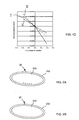
- the invention first relates to a fuel cell element, comprising an assembly (AME) of a membrane, a first and a second electrode, and means for holding this assembly, which form a support on the periphery. thereof and which comprise electrical connection means and fluid circulation means and supply of this fluid to said assembly.
- AME assembly of a membrane
- first and a second electrode means for holding this assembly, which form a support on the periphery. thereof and which comprise electrical connection means and fluid circulation means and supply of this fluid to said assembly.
- a cell or cell element comprises an AME and an AME support, formed, for example molded, at its periphery. All the means of electrical connection, fluid circulation and supply of this fluid to the AME are contained or integrated in this support.
- Each cell or element therefore comprises conductive zones, made in the material forming the support of the AME, for example by overmoulding outside the active zone of the AME. Overmolded conductive areas are compatible with very good continuity and maximum sealing.
- the electrical connection means comprise at least two conductive elements which pass through the support only partially and from different faces of the support, and each of which is connected by a secondary conductor, either to one or the other of the first and second electrodes.
- the various elements of the stack can be welded two by two, for example by welding without adding material, by a technique such as that of the heating mirror.
- the stack of elements may be between an inlet face and an outlet face, the inlet face having gas introduction means, and one of the two inlet and outlet faces. having electrical connection means.
- the gas introduction means comprise at least two flow regulators.
- the electrical connection means can be made by molding a metal insert, or by injecting a conductive polymer into said membrane holding means.
- the electrical connection means are formed by forming at least one opening in said means for holding the membrane, and insertion into this opening of a connector.
- the invention also relates to a method for producing a fuel cell, without joint and without bipolar plates.
- a method for producing a fuel cell without joint and without bipolar plates.
- Such a method comprises an assembly, by welding or gluing, of a plurality of elements according to the invention.
- the invention also relates to a press jaw comprising means for measuring electrical properties of an object in contact with said jaw, and a press comprising two such jaws.
- Electrodes 201, 203 are for example made based on a mixture of graphite and platinum, which mixture may be in the form of a powdered powder rendered partially hydrophobic by a fluoropolymer (Teflon type). On each of these electrodes may be formed a deposit or coating 201 ', 203' of a porous material, for example made of carbon fibers.
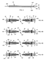
- a cell or cell element comprises an AME 20, 22, 24, 26 and a support 21, 23, 25, 27 of AME (or frame or holding means), molded around the periphery of the AME and made of a thermoplastic material.
- AME or frame or holding means
- each of these supports are also made conductive inserts 30, 31, 30 ', 31', 32, 32 ', 33, 33', 34, 35, 34 ', 35', 36, 37, 37 ', 36' .
- These inserts comprise main conductors 30, 32, 34, 36 and 30 ', 32', 34 ', 36', or lateral conductors, each preferably of substantially rectilinear or cylindrical shape, and also arranged in a direction substantially perpendicular to a plane defined by each of the AMEs 20, 22, 24, 26.
- conductors 31, 31 ', 33, 33', 35, 35 ', 37, 37' said secondary, are arranged by example in a substantially radial manner, for electrically connecting an electrode of the AME of the support in which they are made to the corresponding lateral conductor.
- the conductors 31, 31 ' connect the lateral conductors 30, 30' to each of the electrodes of the membrane 20.
- the conductor 37 '(respectively 37) which connects the lateral conductor 36' ( respectively 36) to one of the electrodes of the membrane 26.
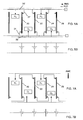
- the Figure 5A schematically represents each of the membranes 20, 22, 24, 26 with its electrical connections 30, 32, 34, 36 and 30 ', 32', 34 ', 36' and the gas injection means.
- This embodiment differs from the preceding simply by the electrical connection means 30, 31, 30 ', 31', 32, 33, 32 ', 33', 34, 35, 34 ', 35', 36, 37, 36 '. , 37 'which make it possible to achieve here a connection of the various elements in series.
- the main sections 30, 30 ', 32, 32', 34, 34 ', 36, 36' do not therefore completely pass through the supports 21, 23, 25, 27 for coating.
- the distribution of the secondary sections or connectors is also different from that of the Figures 4A-4D .
- the connector 31 connects the end of the lateral connector 30 contained in the support 21 to one of the electrodes of the AME 20, while the other connector 31 'connects the other electrode of the AME 20 to the end.
- the second lateral connector 30 ' also located in the support 21.
- the other end of each lateral connector 30, 30' opens on one of the two faces of the element. This distribution is the same for all elements that are connected in series from the electrical point of view.
- references 400, 400, 400 ', 420, 420', 440, 440 ', 460, 460' symbolize gas supply channels from the side channels 40 - 46 and 40 '- 46' in the direction of the SOUL.
- These gas supply channels are made in the volume of the ring or corresponding holding means, without exceeding the outer surfaces 21 ', 21 ", 23', 23", 25 ', 25 ", 27', 27 ", which gives a great compactness to each element.
- An example of channels made in the holding means 21 is given in figure 8 which represents an element seen from the front, with its AME 20 and its support 21.
- secondary channels 400, 400' are etched in the support 21. They can also be obtained during molding or shaping of the material intended to form the support, so unnecessary, then engraving. They define a direction of gas flow substantially in the plane of the support (or the figure 8 ), showing islands 410, 420, 430 (unetched portions of the support 21) that the gases will circumvent during their circulation in the support 21, after introduction through the main channels 40, 40 '. These islets are also visible on the figure 9 , commented further. This flow of gases to the MEA is represented on the figures 8 and 9 by the arrows 411, 421, 431.
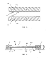
- Inserts 66, 66 'on the Figure 11B allow the connection of the flow regulators or sprinkler blocks on the inlet cover 60. They can be overmolded, or ultrasonically welded, or crimped by expansion.
- An internal connector 70 for positive pole, provides electrical contact between the first face of the first AME 20 and the outer connector 68.
- the inlet cover 60 carries the input and output means of the gas circuits and ensures the maintenance of the two electrical connectors 70 - inserted directly into the input face 76 and inserted in the last element 25, before the outlet face 62. This defines the furthest point of each gas circuit, before returning to the exit points 64, 64 'of the input face 60.
- An advantage of an element structure according to the invention - which has no bipolar plate - is that each element is free from any contact with other elements: there is therefore no contact with bipolar plates such as than those used in the devices of the prior art, which allows a totally free circulation of reactive gases (oxygen and hydrogen) between the MEAs.
- This advantage clearly appears on the stacks of Figures 4A-4D and 6A-6D , on which the active faces 20 ', 20 ", 22', 22", 24 ', 24 ", 26', 26” of the membranes 20, 22, 24, 26 are free from any contact with any other element.
- the gas supply means and the electrical connection means are offset laterally in the AME supports.
- this structure is compatible with any surface and any form of AME: whatever the size of the latter, it can be embedded in a retaining ring such as the rings 21, 23 , 25, 27.
- nanowires for example silicon nanowires, and / or carbon and / or copper and / or aluminum, for example in a proportion of between 1% and 5% by weight.
- the overmolding is seamless, without clamping member and integrates gas distribution channels and water recovery produced at the cathode (these are for example the channels 40, 40 'of the Figure 4A ).
- the second step does not involve overmolding operations of metal inserts, but the simple embodiment by cutting apertures 77, 79 (see FIG. figure 9 ) and the introduction into these openings, corresponding connectors 72.
- the assembly of the elements is preferably carried out by a welding process ( Figures 12A-12E ). As already explained above, gluing is also possible, but less effective from the point of view of sealing.
- a blade 106 (heating mirror) has an internal resistance which allows its surfaces 106 ', 106 "to reach a predetermined temperature.
- the jaws then move the two elements away from the heating blade 106, which is then rapidly removed ( figure 12C ).
- One of the two jaws here the upper jaw, can then be removed ( figure 12E ): the assembly of the two elements is achieved by means of polymer coatings only.
- the jaws 100, 102 of the press 104 may be equipped with means for measuring the resistance or the resistivity through a stack of two or more elements assembled between the two jaws.
- a structure with two jaws that can be advantageously used is therefore illustrated on the figure 13 .
- These two jaws are equipped with means 110, 112 intended to come into contact, for example by studs or contact areas 111, 113, with the contact means located in the coating material.
- a cell structure according to the invention makes it possible to produce a battery, by assembling a plurality of such cells, whose power density is clearly greater than the densities usually encountered in this type of device.
- densities greater than 400 W / kg are easily obtained whereas, with identical membranes of the same size, the known techniques only make it possible to produce cells whose power density is of the order of 200 to 250 W per kilo.
- a battery according to the invention no longer comprises any bipolar plate, or any seal, or any clamping plate.
Landscapes
- Life Sciences & Earth Sciences (AREA)
- Engineering & Computer Science (AREA)
- Manufacturing & Machinery (AREA)
- Sustainable Development (AREA)
- Sustainable Energy (AREA)
- Chemical & Material Sciences (AREA)
- Chemical Kinetics & Catalysis (AREA)
- Electrochemistry (AREA)
- General Chemical & Material Sciences (AREA)
- Fuel Cell (AREA)
Claims (15)
- Brennstoffzellenelement, umfassend:- eine Anordnung aus einer Membran (200), einer ersten und einer zweiten Elektrode (201, 203),- sowie Mittel (21, 23, 25, 27) zum Halten dieser Anordnung, die eine periphere Stütze derselben bilden und die Mittel (30, 31, 30', 31', 32, 33, 32', 33', 34, 35, 34', 35', 36, 37, 36', 37', 72) zur elektrischen Verbindung sowie Mittel (40, 42, 44, 46, 40', 42', 44', 46', 400, 400, 400', 420, 420', 440 440', 460, 460') zum Zirkulieren von Fluid und zum Zuführen dieses Fluids zu der Anordnung umfassen, wobei diese Haltemittel eine Spannung (F, F') auf die Membran derart ausüben, dass diese sich auf jeder Seite der Anordnung aus Membran und Halteelement nicht über eine Fläche (P, P') hinaus verformen kann, die gegen die Außenoberfläche (21', 21") der Abstützung drückt und die im Wesentlichen parallel zur Membran ist.
- Element nach Anspruch 1, wobei die Haltemittel der Anordnung aus einem thermoplastischen Polymer sind.
- Element nach Anspruch 2, wobei das thermoplastische Polymer Polyethylen umfasst, oder Polypropylen, oder Polystyrol, oder COC (Cyclo-Olefin-Cycloaliphat), oder PTFE (oder Teflon), oder PET, oder PEEK (Polyether-Polyazeton), und/oder ferner Kohlenstoff-Nanoröhrchen umfasst oder Ruß oder Silizium-Nanodrähte, und/oder Kohlenstoff und/oder Kupfer und/oder Aluminium.
- Element nach einem der Ansprüche 1 bis 3, wobei die elektrischen Verbindungsmittel wenigstens einen leitenden Einsatz umfassen, der mit wenigstens einer der Elektroden der Membran verbunden ist.
- Element nach einem der Ansprüche 1 bis 4, wobei die elektrischen Verbindungsmittel aus Metall oder aus einem leitenden Polymer sind, beispielsweise einem Polymer mit Kohlenstoff-Nanoröhrchen oder mit Nanodrähten.
- Element nach einem der Ansprüche 1 bis 5, wobei die Elektroden jeder Membran aus Kohlenstofffasern sind oder aus einem Gewebe von Kohlenstofffasern mit Drähten aus Gold oder aus Kupfer oder aus Aluminium, und/oder aus einem porösen Material sind, wobei die Haltemittel der Anordnung aus einem Material sind, das in dieses poröse Material eindringt.
- Element nach einem der Ansprüche 1 bis 6, wobei die Mittel zum Zirkulieren und Zuführen von Fluid seitliche Kanäle (40, 42, 44, 46, 40', 42', 44', 46') umfassen, die die Abstützung durchsetzen, sowie Kanäle (400, 400, 400', 420, 420', 440, 440', 460, 460') zur Verteilung von Fluid von den seitlichen Kanälen hin zu der Membran-Elektroden-Anordnung.
- Element nach dem vorhergehenden Anspruch, wobei die Kanäle zur Verteilung von Fluid Inselchen (410, 420, 430) umfassen, die das Fluid (411, 421, 431) hin zu der Membran-Elektroden-Anordnung führen.
- Element nach einem der Ansprüche 1 bis 8, wobei die elektrischen Verbindungsmittel wenigstens zwei leitende Elemente (30, 30', 32, 32', 34, 34', 36, 36') umfassen:- die die Abstützung durchsetzen und wobei wenigstens eines der beiden mittels eines Sekundärleiters (31, 31', 33, 35, 35', 37) mit der ersten oder der zweiten Elektrode (201, 203) verbunden ist;- und/oder die die Abstützung nur teilweise und von unterschiedlichen Seiten der Abstützung her durchsetzen, und von denen jede mittels eines Sekundärleiters entweder mit der einen oder mit der anderen von der ersten und der zweiten Elektrode verbunden ist.
- Brennstoffzelle, umfassend einen Stapel von Elementen nach einem der Ansprüche 1 bis 9, wobei die Umfangshaltemittel der AME paarweise zugeordnet sind, wobei die elektrischen Verbindungsmittel von benachbarten AME miteinander verbunden sind und wobei die Mittel zum Zirkulieren von Fluid wenigstens einen Fluidströmungskreis durch den Stapel hindurch bilden.
- Brennstoffzelle nach Anspruch 10, wobei die Elemente paarweise verschweißt sind.
- Brennstoffzelle nach einem der Ansprüche 10 oder 11, wobei die elektrischen Verbindungsmittel derart angeordnet sind, dass sie einen Reihenmontagekreis oder einen Parallelmontagekreis oder einen partiellen Reihenmontagekreis oder einen Kreis mit partieller Reihen- und partieller Parallelmontage bilden.
- Brennstoffzelle nach einem der Ansprüche 10 bis 12, wobei der Elementenstapel zwischen einer Eingangsseite (61) und einer Ausgangsseite (62) enthalten ist, wobei die Eingangsseite Mittel (64, 64') zum Einführen von Gas umfasst, die beispielsweise wenigstens zwei Ratenregulierer umfassen, wobei die Eingangsseite oder die Ausgangsseite elektrische Verbindungsmittel (68) umfasst.
- Brennstoffzelle nach Anspruch 13, ferner umfassend Mittel (74), die einen elektrischen Rückkopplungskreis zwischen der Seite, die die elektrischen Verbindungsmittel (68) umfasst, und dem Element (25) des Stapels bilden, das von dieser Seite am weitesten entfernt ist.
- Verfahren zur Herstellung einer Brennstoffzelle, umfassend:a) einen Schritt des Formens der Peripherie einer Anordnung aus einer Membran (200), einer ersten und einer zweiten Elektrode (201, 203), um Mittel (21, 23, 25, 27) zum Halten der Anordnung zu bilden, wobei diese Haltemittel eine Spannung (F, F') auf die Membran derart ausüben, dass sich diese auf jeder Seite der Anordnung aus Membran und Halteelement nicht über eine Fläche (P, P') hinaus verformen kann, die gegen die Außenoberfläche (21', 21") der Abstützung drückt und die im Wesentlichen parallel zur Membran ist,b) einen Schritt der Realisierung, in den Haltemitteln:b1) von Mitteln (30, 31, 30', 31', 32, 33, 32', 33', 34, 35, 34', 35', 36, 37, 36', 37', 72) zur elektrischen Verbindung;b2) von Mitteln (40, 42, 44, 46, 40', 42', 44', 46', 400, 400, 400', 420, 420', 440, 440', 460, 460') zum Zirkulieren von Fluid und zum Zuführen dieses Fluids hin zu der Membran-Elektroden-Anordnung.
Applications Claiming Priority (2)
| Application Number | Priority Date | Filing Date | Title |
|---|---|---|---|
| FR0758551A FR2923086B1 (fr) | 2007-10-24 | 2007-10-24 | Architecture de pile a combustible integre sans joint. |
| PCT/EP2008/064304 WO2009053398A1 (fr) | 2007-10-24 | 2008-10-22 | Architecture de pile a combustible integre sans joint. |
Publications (2)
| Publication Number | Publication Date |
|---|---|
| EP2208249A1 EP2208249A1 (de) | 2010-07-21 |
| EP2208249B1 true EP2208249B1 (de) | 2015-04-01 |
Family
ID=39482260
Family Applications (1)
| Application Number | Title | Priority Date | Filing Date |
|---|---|---|---|
| EP08842695.2A Not-in-force EP2208249B1 (de) | 2007-10-24 | 2008-10-22 | Aufbau einer integrierten brennstoffzelle ohne dichtung |
Country Status (10)
| Country | Link |
|---|---|
| US (1) | US8778555B2 (de) |
| EP (1) | EP2208249B1 (de) |
| JP (1) | JP5650536B2 (de) |
| KR (1) | KR20100101089A (de) |
| CN (1) | CN101919092B (de) |
| AU (1) | AU2008316514B2 (de) |
| BR (1) | BRPI0818878A2 (de) |
| FR (1) | FR2923086B1 (de) |
| WO (1) | WO2009053398A1 (de) |
| ZA (1) | ZA201002635B (de) |
Families Citing this family (3)
| Publication number | Priority date | Publication date | Assignee | Title |
|---|---|---|---|---|
| FR2980644B1 (fr) | 2011-09-22 | 2015-04-10 | Commissariat Energie Atomique | Pile a combustible a haute densite d'assemblages membrane electrodes partageant une cavite fluidique commune |
| US9583884B1 (en) * | 2016-02-26 | 2017-02-28 | Northrop Grumman Systems Corporation | Electrostatic discharge (ESD) safe connector insert |
| US20220328857A1 (en) * | 2019-10-04 | 2022-10-13 | Redflow R&D Pty Ltd | Welded flowing electrolyte battery cell stack |
Family Cites Families (19)
| Publication number | Priority date | Publication date | Assignee | Title |
|---|---|---|---|---|
| FR1593242A (de) * | 1968-03-19 | 1970-05-25 | ||
| JPH01128366A (ja) * | 1987-11-11 | 1989-05-22 | Jgc Corp | 固体電解質型燃料電池 |
| JPH0246661A (ja) * | 1988-08-05 | 1990-02-16 | Meidensha Corp | 積層型燃料電池 |
| IT1270878B (it) | 1993-04-30 | 1997-05-13 | Permelec Spa Nora | Migliorata cella elettrochimica utilizzante membrane a scambio ionico e piatti bipolari metallici |
| DE19703214C2 (de) * | 1997-01-29 | 2003-10-30 | Proton Motor Fuel Cell Gmbh | Membran-Elektrodeneinheit mit integriertem Dichtrand und Verfahren zu ihrer Herstellung |
| DE19713250C2 (de) | 1997-03-29 | 2002-04-18 | Ballard Power Systems | Elektrochemischer Energiewandler mit Polymerelektrolytmembran |
| JPH1128366A (ja) | 1997-07-08 | 1999-02-02 | Babcock Hitachi Kk | 触媒体の製造方法および製造装置 |
| US6531238B1 (en) * | 2000-09-26 | 2003-03-11 | Reliant Energy Power Systems, Inc. | Mass transport for ternary reaction optimization in a proton exchange membrane fuel cell assembly and stack assembly |
| DE10160905B4 (de) | 2001-12-12 | 2007-07-19 | Carl Freudenberg Kg | Dichtungsanordnung für Brennstoffzellen, Verfahren zur Herstellung und Verwendung einer solchen Dichtungsanordnung |
| JP3913573B2 (ja) | 2002-02-26 | 2007-05-09 | 本田技研工業株式会社 | 燃料電池 |
| AU2003248806A1 (en) * | 2002-07-01 | 2004-01-19 | The Regents Of The University Of California | Mems-based fuel cells with integrated catalytic fuel processor and method thereof |
| US20040053100A1 (en) | 2002-09-12 | 2004-03-18 | Stanley Kevin G. | Method of fabricating fuel cells and membrane electrode assemblies |
| US7205062B2 (en) | 2002-11-22 | 2007-04-17 | The Research Foundation Of State University Of New York | Fuel cell stack |
| US7070879B2 (en) * | 2003-04-10 | 2006-07-04 | Hewlett-Packard Development Company, L.P. | Fuel cell or electrodes with passive support |
| JP4031740B2 (ja) * | 2003-07-15 | 2008-01-09 | 日東電工株式会社 | 燃料電池用セパレータ及びそれを用いた燃料電池 |
| US7521145B2 (en) * | 2003-10-16 | 2009-04-21 | Wistron Corp. | Fuel cells for use in portable devices |
| JP2005322543A (ja) * | 2004-05-10 | 2005-11-17 | Yuasa Corp | 燃料電池スタック |
| DE102005051583A1 (de) * | 2005-10-27 | 2007-05-03 | Airbus Deutschland Gmbh | Brennstoffzellensystem für die Versorgung von Luftfahrzeugen |
| EP1982372B1 (de) * | 2006-01-17 | 2020-10-21 | Henkel IP & Holding GmbH | Dichtstoff für integrierte brennstoffzellenkomponenten sowie herstellungsverfahren und systeme dafür |
-
2007
- 2007-10-24 FR FR0758551A patent/FR2923086B1/fr not_active Expired - Fee Related
-
2008
- 2008-10-22 BR BRPI0818878-5A patent/BRPI0818878A2/pt not_active IP Right Cessation
- 2008-10-22 WO PCT/EP2008/064304 patent/WO2009053398A1/fr not_active Ceased
- 2008-10-22 AU AU2008316514A patent/AU2008316514B2/en not_active Ceased
- 2008-10-22 CN CN200880122431.8A patent/CN101919092B/zh not_active Expired - Fee Related
- 2008-10-22 JP JP2010530444A patent/JP5650536B2/ja not_active Expired - Fee Related
- 2008-10-22 KR KR1020107010550A patent/KR20100101089A/ko not_active Abandoned
- 2008-10-22 EP EP08842695.2A patent/EP2208249B1/de not_active Not-in-force
- 2008-10-22 US US12/738,930 patent/US8778555B2/en active Active
-
2010
- 2010-04-15 ZA ZA2010/02635A patent/ZA201002635B/en unknown
Also Published As
| Publication number | Publication date |
|---|---|
| AU2008316514B2 (en) | 2013-09-26 |
| CN101919092A (zh) | 2010-12-15 |
| FR2923086A1 (fr) | 2009-05-01 |
| ZA201002635B (en) | 2011-06-29 |
| AU2008316514A1 (en) | 2009-04-30 |
| KR20100101089A (ko) | 2010-09-16 |
| JP5650536B2 (ja) | 2015-01-07 |
| US8778555B2 (en) | 2014-07-15 |
| BRPI0818878A2 (pt) | 2015-05-05 |
| CN101919092B (zh) | 2014-05-28 |
| EP2208249A1 (de) | 2010-07-21 |
| FR2923086B1 (fr) | 2010-12-10 |
| US20100239938A1 (en) | 2010-09-23 |
| JP2011501371A (ja) | 2011-01-06 |
| WO2009053398A1 (fr) | 2009-04-30 |
Similar Documents
| Publication | Publication Date | Title |
|---|---|---|
| EP2061114B1 (de) | Brennstoffzelle, bestehend aus mehreren Elementarzellen, die durch Serienschaltung mit den Stromkollektoren miteinander verbunden sind | |
| EP3179532B1 (de) | Dichter querträger vom typ glas-metall, seine verwendung für elektrochemischen lithiumakkumulator und entsprechendes herstellungsverfahren | |
| EP3130020B1 (de) | Elektrochemischer lithium-ionen-akku mit direkt an die elektrodenanordnung angeschlossenem anschluss und zugehöriges herstellungsverfahren | |
| FR2568412A1 (fr) | Perfectionnements aux structures des piles a combustible. | |
| EP2093820B1 (de) | Elektrische Verbindung für Stromakkumulator | |
| EP2208249B1 (de) | Aufbau einer integrierten brennstoffzelle ohne dichtung | |
| EP2556553B1 (de) | Verbesserter elektrochemischer wandler | |
| FR3023981A1 (fr) | Plaque bipolaire pour reacteur electrochimique a zone d'homogeneisation compacte et a faible differentiel de pression | |
| FR2889888A1 (fr) | Membrane polymere composite a conduction ionique/electronique, ses procedes de fabrication et coeur de pile a combustible planaire la comprenant | |
| EP2707920B1 (de) | Brennstoffzelle mit verteilern mit individuellen injektordichtungen | |
| CA2710429A1 (fr) | Liaison souple etanche entre un substrat metallique et un substrat ceramique, procede de realisation d'une telle liaison, application du procede a l'etancheite d'electrolyseurs haute temperature et des piles a combustible | |
| EP3035411A1 (de) | Verbindungsverfahren in einem akkumulator, und so verbundener akkumulator | |
| FR2911219A1 (fr) | Plaque bipolaire pour pile a combustible a membrane polymere | |
| WO2003100896A2 (fr) | Cellule elementaire pour pile a combustible a structure helicoïdale, procede de fabrication et pile a combustible comprenant une pluralite de cellules elementaires | |
| EP4434105B1 (de) | System und verfahren zum zusammenfügen von bipolarplatten aus verbundmaterial einer electrochemischen vorrichtung | |
| EP3103154B1 (de) | Verfahren zum vereinfachten stapeln von membran-elektroden-einheiten | |
| FR3110777A1 (fr) | Système et procédé de solidarisation de plaques bipolaires en matériau composite d’un dispositif électrochimique | |
| FR3000615A1 (fr) | Connecteur pour cellules de pile a combustible et procede de mise en oeuvre | |
| FR3143214A1 (fr) | Module de batterie ou pack-batterie, comprenant une matrice à accumulateurs de format cylindrique, logée et bridée dans un boitier périphérique. | |
| WO2025141011A1 (fr) | Procédé de fabrication d'un dispositif électrochimique et dispositif associé | |
| WO2025257283A1 (fr) | Dispositif électrochimique, ensemble comprenant plusieurs dispositifs électrochimiques, véhicule automobile et procédé d'assemblage du dispositif électrochimique | |
| EP4133543A1 (de) | Elektrochemisches element für eine batterie und entsprechende batterie | |
| WO2021014104A1 (fr) | Pile à combustible à membrane polymère électrolyte | |
| CA3178183A1 (fr) | Plaque separatrice bipolaire pour pile a combustible, pile a combustible et procede de fabrication associes | |
| FR2932612A1 (fr) | Plaque separatrice a double gorge pour pile a combustible |
Legal Events
| Date | Code | Title | Description |
|---|---|---|---|
| PUAI | Public reference made under article 153(3) epc to a published international application that has entered the european phase |
Free format text: ORIGINAL CODE: 0009012 |
|
| 17P | Request for examination filed |
Effective date: 20100415 |
|
| AK | Designated contracting states |
Kind code of ref document: A1 Designated state(s): AT BE BG CH CY CZ DE DK EE ES FI FR GB GR HR HU IE IS IT LI LT LU LV MC MT NL NO PL PT RO SE SI SK TR |
|
| AX | Request for extension of the european patent |
Extension state: AL BA MK RS |
|
| DAX | Request for extension of the european patent (deleted) | ||
| 17Q | First examination report despatched |
Effective date: 20130416 |
|
| GRAP | Despatch of communication of intention to grant a patent |
Free format text: ORIGINAL CODE: EPIDOSNIGR1 |
|
| INTG | Intention to grant announced |
Effective date: 20141021 |
|
| GRAS | Grant fee paid |
Free format text: ORIGINAL CODE: EPIDOSNIGR3 |
|
| GRAA | (expected) grant |
Free format text: ORIGINAL CODE: 0009210 |
|
| AK | Designated contracting states |
Kind code of ref document: B1 Designated state(s): AT BE BG CH CY CZ DE DK EE ES FI FR GB GR HR HU IE IS IT LI LT LU LV MC MT NL NO PL PT RO SE SI SK TR |
|
| REG | Reference to a national code |
Ref country code: GB Ref legal event code: FG4D Free format text: NOT ENGLISH |
|
| REG | Reference to a national code |
Ref country code: CH Ref legal event code: EP |
|
| REG | Reference to a national code |
Ref country code: IE Ref legal event code: FG4D Free format text: LANGUAGE OF EP DOCUMENT: FRENCH |
|
| REG | Reference to a national code |
Ref country code: DE Ref legal event code: R096 Ref document number: 602008037455 Country of ref document: DE Effective date: 20150513 |
|
| REG | Reference to a national code |
Ref country code: AT Ref legal event code: REF Ref document number: 719559 Country of ref document: AT Kind code of ref document: T Effective date: 20150515 |
|
| REG | Reference to a national code |
Ref country code: NL Ref legal event code: VDEP Effective date: 20150401 |
|
| REG | Reference to a national code |
Ref country code: AT Ref legal event code: MK05 Ref document number: 719559 Country of ref document: AT Kind code of ref document: T Effective date: 20150401 |
|
| REG | Reference to a national code |
Ref country code: LT Ref legal event code: MG4D |
|
| PG25 | Lapsed in a contracting state [announced via postgrant information from national office to epo] |
Ref country code: NL Free format text: LAPSE BECAUSE OF FAILURE TO SUBMIT A TRANSLATION OF THE DESCRIPTION OR TO PAY THE FEE WITHIN THE PRESCRIBED TIME-LIMIT Effective date: 20150401 |
|
| PG25 | Lapsed in a contracting state [announced via postgrant information from national office to epo] |
Ref country code: ES Free format text: LAPSE BECAUSE OF FAILURE TO SUBMIT A TRANSLATION OF THE DESCRIPTION OR TO PAY THE FEE WITHIN THE PRESCRIBED TIME-LIMIT Effective date: 20150401 Ref country code: PT Free format text: LAPSE BECAUSE OF FAILURE TO SUBMIT A TRANSLATION OF THE DESCRIPTION OR TO PAY THE FEE WITHIN THE PRESCRIBED TIME-LIMIT Effective date: 20150803 Ref country code: CZ Free format text: LAPSE BECAUSE OF FAILURE TO SUBMIT A TRANSLATION OF THE DESCRIPTION OR TO PAY THE FEE WITHIN THE PRESCRIBED TIME-LIMIT Effective date: 20150401 Ref country code: NO Free format text: LAPSE BECAUSE OF FAILURE TO SUBMIT A TRANSLATION OF THE DESCRIPTION OR TO PAY THE FEE WITHIN THE PRESCRIBED TIME-LIMIT Effective date: 20150701 Ref country code: HR Free format text: LAPSE BECAUSE OF FAILURE TO SUBMIT A TRANSLATION OF THE DESCRIPTION OR TO PAY THE FEE WITHIN THE PRESCRIBED TIME-LIMIT Effective date: 20150401 Ref country code: LT Free format text: LAPSE BECAUSE OF FAILURE TO SUBMIT A TRANSLATION OF THE DESCRIPTION OR TO PAY THE FEE WITHIN THE PRESCRIBED TIME-LIMIT Effective date: 20150401 Ref country code: FI Free format text: LAPSE BECAUSE OF FAILURE TO SUBMIT A TRANSLATION OF THE DESCRIPTION OR TO PAY THE FEE WITHIN THE PRESCRIBED TIME-LIMIT Effective date: 20150401 |
|
| REG | Reference to a national code |
Ref country code: FR Ref legal event code: PLFP Year of fee payment: 8 |
|
| PG25 | Lapsed in a contracting state [announced via postgrant information from national office to epo] |
Ref country code: AT Free format text: LAPSE BECAUSE OF FAILURE TO SUBMIT A TRANSLATION OF THE DESCRIPTION OR TO PAY THE FEE WITHIN THE PRESCRIBED TIME-LIMIT Effective date: 20150401 Ref country code: IS Free format text: LAPSE BECAUSE OF FAILURE TO SUBMIT A TRANSLATION OF THE DESCRIPTION OR TO PAY THE FEE WITHIN THE PRESCRIBED TIME-LIMIT Effective date: 20150801 Ref country code: GR Free format text: LAPSE BECAUSE OF FAILURE TO SUBMIT A TRANSLATION OF THE DESCRIPTION OR TO PAY THE FEE WITHIN THE PRESCRIBED TIME-LIMIT Effective date: 20150702 Ref country code: LV Free format text: LAPSE BECAUSE OF FAILURE TO SUBMIT A TRANSLATION OF THE DESCRIPTION OR TO PAY THE FEE WITHIN THE PRESCRIBED TIME-LIMIT Effective date: 20150401 |
|
| REG | Reference to a national code |
Ref country code: DE Ref legal event code: R097 Ref document number: 602008037455 Country of ref document: DE |
|
| PG25 | Lapsed in a contracting state [announced via postgrant information from national office to epo] |
Ref country code: EE Free format text: LAPSE BECAUSE OF FAILURE TO SUBMIT A TRANSLATION OF THE DESCRIPTION OR TO PAY THE FEE WITHIN THE PRESCRIBED TIME-LIMIT Effective date: 20150401 Ref country code: DK Free format text: LAPSE BECAUSE OF FAILURE TO SUBMIT A TRANSLATION OF THE DESCRIPTION OR TO PAY THE FEE WITHIN THE PRESCRIBED TIME-LIMIT Effective date: 20150401 |
|
| PGFP | Annual fee paid to national office [announced via postgrant information from national office to epo] |
Ref country code: IT Payment date: 20151014 Year of fee payment: 8 |
|
| PLBE | No opposition filed within time limit |
Free format text: ORIGINAL CODE: 0009261 |
|
| STAA | Information on the status of an ep patent application or granted ep patent |
Free format text: STATUS: NO OPPOSITION FILED WITHIN TIME LIMIT |
|
| PG25 | Lapsed in a contracting state [announced via postgrant information from national office to epo] |
Ref country code: SK Free format text: LAPSE BECAUSE OF FAILURE TO SUBMIT A TRANSLATION OF THE DESCRIPTION OR TO PAY THE FEE WITHIN THE PRESCRIBED TIME-LIMIT Effective date: 20150401 Ref country code: PL Free format text: LAPSE BECAUSE OF FAILURE TO SUBMIT A TRANSLATION OF THE DESCRIPTION OR TO PAY THE FEE WITHIN THE PRESCRIBED TIME-LIMIT Effective date: 20150401 Ref country code: RO Free format text: LAPSE BECAUSE OF NON-PAYMENT OF DUE FEES Effective date: 20150401 |
|
| 26N | No opposition filed |
Effective date: 20160105 |
|
| PG25 | Lapsed in a contracting state [announced via postgrant information from national office to epo] |
Ref country code: SI Free format text: LAPSE BECAUSE OF FAILURE TO SUBMIT A TRANSLATION OF THE DESCRIPTION OR TO PAY THE FEE WITHIN THE PRESCRIBED TIME-LIMIT Effective date: 20150401 Ref country code: LU Free format text: LAPSE BECAUSE OF FAILURE TO SUBMIT A TRANSLATION OF THE DESCRIPTION OR TO PAY THE FEE WITHIN THE PRESCRIBED TIME-LIMIT Effective date: 20151022 |
|
| REG | Reference to a national code |
Ref country code: CH Ref legal event code: PL |
|
| PG25 | Lapsed in a contracting state [announced via postgrant information from national office to epo] |
Ref country code: MC Free format text: LAPSE BECAUSE OF FAILURE TO SUBMIT A TRANSLATION OF THE DESCRIPTION OR TO PAY THE FEE WITHIN THE PRESCRIBED TIME-LIMIT Effective date: 20150401 |
|
| REG | Reference to a national code |
Ref country code: IE Ref legal event code: MM4A |
|
| PG25 | Lapsed in a contracting state [announced via postgrant information from national office to epo] |
Ref country code: LI Free format text: LAPSE BECAUSE OF NON-PAYMENT OF DUE FEES Effective date: 20151031 Ref country code: CH Free format text: LAPSE BECAUSE OF NON-PAYMENT OF DUE FEES Effective date: 20151031 |
|
| REG | Reference to a national code |
Ref country code: FR Ref legal event code: PLFP Year of fee payment: 9 |
|
| PG25 | Lapsed in a contracting state [announced via postgrant information from national office to epo] |
Ref country code: IE Free format text: LAPSE BECAUSE OF NON-PAYMENT OF DUE FEES Effective date: 20151022 |
|
| PG25 | Lapsed in a contracting state [announced via postgrant information from national office to epo] |
Ref country code: BG Free format text: LAPSE BECAUSE OF FAILURE TO SUBMIT A TRANSLATION OF THE DESCRIPTION OR TO PAY THE FEE WITHIN THE PRESCRIBED TIME-LIMIT Effective date: 20150401 Ref country code: HU Free format text: LAPSE BECAUSE OF FAILURE TO SUBMIT A TRANSLATION OF THE DESCRIPTION OR TO PAY THE FEE WITHIN THE PRESCRIBED TIME-LIMIT; INVALID AB INITIO Effective date: 20081022 |
|
| PG25 | Lapsed in a contracting state [announced via postgrant information from national office to epo] |
Ref country code: SE Free format text: LAPSE BECAUSE OF FAILURE TO SUBMIT A TRANSLATION OF THE DESCRIPTION OR TO PAY THE FEE WITHIN THE PRESCRIBED TIME-LIMIT Effective date: 20150401 Ref country code: CY Free format text: LAPSE BECAUSE OF FAILURE TO SUBMIT A TRANSLATION OF THE DESCRIPTION OR TO PAY THE FEE WITHIN THE PRESCRIBED TIME-LIMIT Effective date: 20150401 |
|
| PG25 | Lapsed in a contracting state [announced via postgrant information from national office to epo] |
Ref country code: BE Free format text: LAPSE BECAUSE OF NON-PAYMENT OF DUE FEES Effective date: 20151031 |
|
| PG25 | Lapsed in a contracting state [announced via postgrant information from national office to epo] |
Ref country code: MT Free format text: LAPSE BECAUSE OF FAILURE TO SUBMIT A TRANSLATION OF THE DESCRIPTION OR TO PAY THE FEE WITHIN THE PRESCRIBED TIME-LIMIT Effective date: 20150401 Ref country code: TR Free format text: LAPSE BECAUSE OF FAILURE TO SUBMIT A TRANSLATION OF THE DESCRIPTION OR TO PAY THE FEE WITHIN THE PRESCRIBED TIME-LIMIT Effective date: 20150401 |
|
| PG25 | Lapsed in a contracting state [announced via postgrant information from national office to epo] |
Ref country code: IT Free format text: LAPSE BECAUSE OF NON-PAYMENT OF DUE FEES Effective date: 20161022 |
|
| REG | Reference to a national code |
Ref country code: FR Ref legal event code: PLFP Year of fee payment: 10 |
|
| REG | Reference to a national code |
Ref country code: FR Ref legal event code: PLFP Year of fee payment: 11 |
|
| PGFP | Annual fee paid to national office [announced via postgrant information from national office to epo] |
Ref country code: FR Payment date: 20221020 Year of fee payment: 15 |
|
| PGFP | Annual fee paid to national office [announced via postgrant information from national office to epo] |
Ref country code: GB Payment date: 20221024 Year of fee payment: 15 Ref country code: DE Payment date: 20221020 Year of fee payment: 15 |
|
| REG | Reference to a national code |
Ref country code: DE Ref legal event code: R119 Ref document number: 602008037455 Country of ref document: DE |
|
| GBPC | Gb: european patent ceased through non-payment of renewal fee |
Effective date: 20231022 |
|
| PG25 | Lapsed in a contracting state [announced via postgrant information from national office to epo] |
Ref country code: GB Free format text: LAPSE BECAUSE OF NON-PAYMENT OF DUE FEES Effective date: 20231022 |
|
| PG25 | Lapsed in a contracting state [announced via postgrant information from national office to epo] |
Ref country code: GB Free format text: LAPSE BECAUSE OF NON-PAYMENT OF DUE FEES Effective date: 20231022 Ref country code: FR Free format text: LAPSE BECAUSE OF NON-PAYMENT OF DUE FEES Effective date: 20231031 Ref country code: DE Free format text: LAPSE BECAUSE OF NON-PAYMENT OF DUE FEES Effective date: 20240501 |