EP2026643A2 - Boîtier hermétique, en particulier pour commutations électroniques - Google Patents
Boîtier hermétique, en particulier pour commutations électroniques Download PDFInfo
- Publication number
- EP2026643A2 EP2026643A2 EP08104693A EP08104693A EP2026643A2 EP 2026643 A2 EP2026643 A2 EP 2026643A2 EP 08104693 A EP08104693 A EP 08104693A EP 08104693 A EP08104693 A EP 08104693A EP 2026643 A2 EP2026643 A2 EP 2026643A2
- Authority
- EP
- European Patent Office
- Prior art keywords
- base plate
- housing
- housing base
- cover
- lid
- Prior art date
- Legal status (The legal status is an assumption and is not a legal conclusion. Google has not performed a legal analysis and makes no representation as to the accuracy of the status listed.)
- Granted
Links
Images


Classifications
-
- H—ELECTRICITY
- H05—ELECTRIC TECHNIQUES NOT OTHERWISE PROVIDED FOR
- H05K—PRINTED CIRCUITS; CASINGS OR CONSTRUCTIONAL DETAILS OF ELECTRIC APPARATUS; MANUFACTURE OF ASSEMBLAGES OF ELECTRICAL COMPONENTS
- H05K5/00—Casings, cabinets or drawers for electric apparatus
- H05K5/06—Hermetically-sealed casings
- H05K5/063—Hermetically-sealed casings sealed by a labyrinth structure provided at the joining parts
-
- B—PERFORMING OPERATIONS; TRANSPORTING
- B81—MICROSTRUCTURAL TECHNOLOGY
- B81B—MICROSTRUCTURAL DEVICES OR SYSTEMS, e.g. MICROMECHANICAL DEVICES
- B81B7/00—Microstructural systems ; Auxiliary parts of microstructural devices or systems
- B81B7/0032—Packages or encapsulation
- B81B7/0064—Packages or encapsulation for protecting against electromagnetic or electrostatic interferences
-
- B—PERFORMING OPERATIONS; TRANSPORTING
- B81—MICROSTRUCTURAL TECHNOLOGY
- B81C—PROCESSES OR APPARATUS SPECIALLY ADAPTED FOR THE MANUFACTURE OR TREATMENT OF MICROSTRUCTURAL DEVICES OR SYSTEMS
- B81C1/00—Manufacture or treatment of devices or systems in or on a substrate
- B81C1/00015—Manufacture or treatment of devices or systems in or on a substrate for manufacturing microsystems
- B81C1/00261—Processes for packaging MEMS devices
- B81C1/00269—Bonding of solid lids or wafers to the substrate
-
- G—PHYSICS
- G01—MEASURING; TESTING
- G01C—MEASURING DISTANCES, LEVELS OR BEARINGS; SURVEYING; NAVIGATION; GYROSCOPIC INSTRUMENTS; PHOTOGRAMMETRY OR VIDEOGRAMMETRY
- G01C19/00—Gyroscopes; Turn-sensitive devices using vibrating masses; Turn-sensitive devices without moving masses; Measuring angular rate using gyroscopic effects
- G01C19/56—Turn-sensitive devices using vibrating masses, e.g. vibratory angular rate sensors based on Coriolis forces
-
- G—PHYSICS
- G01—MEASURING; TESTING
- G01D—MEASURING NOT SPECIALLY ADAPTED FOR A SPECIFIC VARIABLE; ARRANGEMENTS FOR MEASURING TWO OR MORE VARIABLES NOT COVERED IN A SINGLE OTHER SUBCLASS; TARIFF METERING APPARATUS; MEASURING OR TESTING NOT OTHERWISE PROVIDED FOR
- G01D11/00—Component parts of measuring arrangements not specially adapted for a specific variable
- G01D11/24—Housings ; Casings for instruments
- G01D11/245—Housings for sensors
-
- G—PHYSICS
- G01—MEASURING; TESTING
- G01P—MEASURING LINEAR OR ANGULAR SPEED, ACCELERATION, DECELERATION, OR SHOCK; INDICATING PRESENCE, ABSENCE, OR DIRECTION, OF MOVEMENT
- G01P1/00—Details of instruments
- G01P1/02—Housings
- G01P1/026—Housings for speed measuring devices, e.g. pulse generator
-
- B—PERFORMING OPERATIONS; TRANSPORTING
- B81—MICROSTRUCTURAL TECHNOLOGY
- B81C—PROCESSES OR APPARATUS SPECIALLY ADAPTED FOR THE MANUFACTURE OR TREATMENT OF MICROSTRUCTURAL DEVICES OR SYSTEMS
- B81C2203/00—Forming microstructural systems
- B81C2203/01—Packaging MEMS
- B81C2203/0109—Bonding an individual cap on the substrate
Definitions
- the present invention relates to a hermetically sealed housing, in particular for electronic circuits, in which a substantially rectangular cover is welded by means of resistance welding to a housing base plate.
- a substantially rectangular cover is welded by means of resistance welding to a housing base plate.
- the lid on the edge regions on a flange which rests flat on the base plate.
- the cover further has a predetermined radius at each of the four corner regions and surrounds a step arranged on the base plate such that the cover flange completely surrounds the step of the base plate in the interior of the housing.
- the cover on the base plate by only four points of contact, one at each corner, exactly centered, so that the straight portions of the side cover walls to the stage of the housing base plate have a predetermined and circumferentially equal gap by the centering of the lid on the housing base plate such that the inner radii of the corners of the lid have a larger radius than the radii of the rounded corners of the revolving on the base plate stage.
- hermetically sealed housing are known from the prior art, which are produced by resistance welding of a lid to a housing base plate.
- these housing between the lid side wall and the step of the base plate on a circumferential, equal gap, so that the lid can slip during resistance welding and can inject any weld spatter through molten material into the interior of the hermetically sealed housing.
- the essence of the present invention is to provide a hermetically sealed housing in which the cover and the housing base plate are matched to one another such that the housing cover independently adjusts exactly on the housing base plate during resistance welding and the gap between the cover side walls and the housing base plate so small dimensioned is that at the same time any spatter can not get into the housing interior by the resistance welding. According to the invention this is solved by the features of the independent claim. Advantageous developments and refinements emerge from the subclaims.
- the side walls of the lid and the step of the housing base plate are dimensioned so that touch the lid side walls and the step of the housing base plate at each corner in only one point. These points of contact on each housing corner allow for an exact self-adjustment of the cover on the base plate during resistance welding.
- the flange of the lid is fixed to the housing base plate by means of resistance welding.
- a hermetically sealed seal of the housing is achieved since the cover flange is fixed circumferentially on the housing base plate.
- the region of the housing base plate, on which the flange of the lid is welded has a welding edge, which is designed as a peripheral elevation, in particular with a V-shaped cross section.
- This circumferential increase, which serves as a welding edge is advantageously made of the base material steel, which is coated with a nickel surface.
- This welding edge can be made in one piece with the production of the base plate.
- the cover and the housing base plate are made of metal. This results in the advantage that heat generated in the interior of the housing is effectively conducted to the outside, and that a high immunity to electromagnetic radiation is achieved. Furthermore, the production of a metallic material allows the cover and the housing base plate to be connected to one another by means of the resistance welding process.
- components are arranged in the interior of the lid, which are to be adjusted exactly to the components on the base plate.
- the hermetically sealed housing is fastened to a further carrier element by means of the lid part, so that the accuracy of the functional capability of micromechanical components in the interior depends on the accuracy of the adjustment of the lid to the housing base plate.
- the hermetically sealed housing is pressed by means of the cover part in a rotation rate sensor holder, so that the accuracy of the function of the micromechanical components on the base plate depends on the adjustment of the cover to the housing base plate.
- the predetermined gap between the straight sections of the side cover walls and the step of the housing base plate is dimensioned such that no welding spatters penetrate into the interior of the housing during resistance welding. This is important if inside the hermetically sealed housing open semiconductor chips or micromechanical components are installed, which would be affected by penetrating metal particles as a result of resistance welding in their function or even destroyed. As a result, the reject rate during lid assembly is advantageously reduced effectively. It is particularly advantageous that the predetermined gap is about 0.05 mm wide.
- the housing includes a rotation rate sensor, as used for example in motor vehicles.
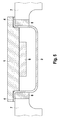
- FIG. 1 the overall representation of a housing according to the invention is shown.
- a housing base plate 1 which has a stage, not shown, which is designed such that the inner region of the housing base plate relative to the visible, outer edge is increased and mounted on this elevated level electronic components and / or a rotation rate sensor.
- a cover 2 is placed, which receives the elevated level of the support base plate in the interior and together with the housing base plate 1 forms the hermetically sealed housing.
- a peripheral cover flange 3 is shown on the outer edge of the lid 2, which is executed parallel to the cover cover and approximately perpendicular to the cover walls and rests flat on the housing base plate 1.
- this cover flange 3 it is possible to weld the cover 2 and the housing base plate 1 together, for example by a resistance welding method known from the prior art.
- FIG. 2 is sketchy an exemplary corner of the in FIG. 1 illustrated housing shown in plan view.
- the housing base plate 1 stage which is diagonally hatched and at the corners has curves, the corners of the step are rounded with the radius Ri.
- the lid 2 is shown, which consists of a hatched area, which has a hatching orthogonal to the hatching of the step of the housing base plate 1, and which represents the perpendicular top wall and consists of the unshaded area 3, which is aligned parallel to the lid cover cover flange 3, which rests flat on the housing base plate 1.
- the corner of the housing cover was designed so that the inside rounded corners of the cover walls also have a predefined radius Ra, which has a larger radius compared to the radius Ri the stage of the housing base plate 1.
- the dimensions of the step on the housing base plate 1, as well as the inner dimensions of the housing cover 2 are dimensioned such that two opposite cover walls have a greater light dimension than the step of the housing base plate 1 is wide. This results in that the straight sections between the step of the housing base plate 1 and the cover walls have a gap 5 which is the same size on all sides, but which has been dimensioned so small that resistance welding of the cover flange 3 to the housing base plate 1 does not result in spatters of molten material into the interior the hermetically sealed housing can get.
- a resistance welding is performed, in which the housing flange is welded around with the housing base plate.
- the housing base plate 1 is usually made of an electrically conductive material to allow the resistance welding at all, there is a risk that flows through contact points between the cover 2 and the edge of the step of the housing base plate 1 currents that do not flow over the cover flange 3 and thus represent an undesirable leakage current. Due to the special dimensioning of the lid and the housing base plate cover and base plate, however, touch only in one point per corner, so that these leakage currents are extremely low and the inventive compound between the cover and housing base plate is only made possible by resistance welding.
- FIG. 3 is a sectional view shown, along the section line AA 'according to FIG. 2 results.
- the lid and the housing base plate was placed diagonally through the contact point between the cover 2 and the step of the housing base plate 1, so that it can be seen here that between the housing base plate 1 and the cover 2 no gap is present and the side wall of the lid 2 directly to the Stage of the housing base plate 1 is applied.
- the housing flange 3 can be seen, which rests flat on the housing base plate 1 and can be connected by means of resistance welding with this.
- the welding edge 4 is shown, which is designed as a circumferential, V-shaped elevation on the housing base plate 1 in the region which is welded to the flange 3 of the lid 2.
- FIG. 4 is compared to FIG. 3 a section through one of the straight sections between the cover 2 and the housing base plate 1 shown in which, in contrast to FIG. 3 a gap 5 is provided between the lid side wall and the housing base plate 1, whereby leakage currents which flow off via the step of the housing base plate 1 are avoided. Also in FIG. 4 is the cover flange 3, and the welding edge 4 is shown.
- This device is particularly advantageous in the event that components on the inside of the lid cover 2 are fixed, which are to be adjusted exactly opposite corresponding components, which are arranged on the housing base plate.
- FIG. 5 the assembly of the hermetically sealed housing is shown on a housing support 7, wherein the hermetically sealed housing is pressed by means of the cover 2 in a holder 8.
- This assembly is particularly advantageous in a vehicle dynamics control (ESP), in which inside the housing on the housing base plate 1 micromechanical elements 9 for realizing a rotation rate sensor.
- ESP vehicle dynamics control
- the accuracy of the operation of the rotation rate sensor on the one hand by the accuracy of the pressing of the fully assembled housing, consisting of cover 2 and housing base plate 1, in the holder 8 of the housing support 7 is dependent;
- the accuracy of the operation of the rotation rate sensor of the accuracy of the mounting of the cover 2 with respect to the housing base plate 1 is dependent, which is why in this case a particularly accurate mounting of the cover 2 on the housing base plate 1 is necessary.
Landscapes
- Engineering & Computer Science (AREA)
- Microelectronics & Electronic Packaging (AREA)
- Physics & Mathematics (AREA)
- General Physics & Mathematics (AREA)
- Manufacturing & Machinery (AREA)
- Radar, Positioning & Navigation (AREA)
- Remote Sensing (AREA)
- Electromagnetism (AREA)
- Computer Hardware Design (AREA)
- Casings For Electric Apparatus (AREA)
Applications Claiming Priority (1)
| Application Number | Priority Date | Filing Date | Title |
|---|---|---|---|
| DE200710038989 DE102007038989A1 (de) | 2007-08-17 | 2007-08-17 | Hermetisch dichtes Gehäuse, insbesondere für elektronische Schaltungen |
Publications (3)
| Publication Number | Publication Date |
|---|---|
| EP2026643A2 true EP2026643A2 (fr) | 2009-02-18 |
| EP2026643A3 EP2026643A3 (fr) | 2010-06-02 |
| EP2026643B1 EP2026643B1 (fr) | 2011-05-25 |
Family
ID=40019441
Family Applications (1)
| Application Number | Title | Priority Date | Filing Date |
|---|---|---|---|
| EP20080104693 Active EP2026643B1 (fr) | 2007-08-17 | 2008-07-10 | Boîtier hermétique, en particulier pour commutations électroniques |
Country Status (2)
| Country | Link |
|---|---|
| EP (1) | EP2026643B1 (fr) |
| DE (1) | DE102007038989A1 (fr) |
Cited By (1)
| Publication number | Priority date | Publication date | Assignee | Title |
|---|---|---|---|---|
| WO2014079713A1 (fr) * | 2012-11-26 | 2014-05-30 | R. Stahl Schaltgeräte GmbH | Boîtier soudé en matière thermoplastique résistant à la pression protégé contre des explosions |
Family Cites Families (4)
| Publication number | Priority date | Publication date | Assignee | Title |
|---|---|---|---|---|
| JPS60163518A (ja) * | 1984-02-03 | 1985-08-26 | Maruyasu Kogyo Kk | 弾性表面波フイルタ装置 |
| US5248849A (en) * | 1989-11-15 | 1993-09-28 | Modelec S.A. | Spray-protected connection housing for electrical consumers |
| JPH11168349A (ja) * | 1997-12-03 | 1999-06-22 | Daishinku:Kk | 電子部品および圧電振動子 |
| JP5037819B2 (ja) * | 2005-03-04 | 2012-10-03 | ソニー株式会社 | 電子機器 |
-
2007
- 2007-08-17 DE DE200710038989 patent/DE102007038989A1/de not_active Withdrawn
-
2008
- 2008-07-10 EP EP20080104693 patent/EP2026643B1/fr active Active
Cited By (1)
| Publication number | Priority date | Publication date | Assignee | Title |
|---|---|---|---|---|
| WO2014079713A1 (fr) * | 2012-11-26 | 2014-05-30 | R. Stahl Schaltgeräte GmbH | Boîtier soudé en matière thermoplastique résistant à la pression protégé contre des explosions |
Also Published As
| Publication number | Publication date |
|---|---|
| EP2026643A3 (fr) | 2010-06-02 |
| DE102007038989A1 (de) | 2009-02-19 |
| EP2026643B1 (fr) | 2011-05-25 |
Similar Documents
| Publication | Publication Date | Title |
|---|---|---|
| EP3031564B1 (fr) | Element auxiliaire pour etre presse dans une premiere piece dans un procede de soudage de pieces non soudables directement | |
| EP3066749B1 (fr) | Machine électrique comportant une bride de fixation | |
| WO2005012740A1 (fr) | Articulation spherique et composant pourvu d'une telle articulation | |
| EP2054270B1 (fr) | Systeme de camera, notamment pour un systeme d'acquisition de l'environnement d'un vehicule, et procede de montage | |
| WO2018019400A1 (fr) | Élément d'étanchéité pour la liaison étanche au fluide et électro-conductrice d'une première pièce et d'une deuxième pièce, ainsi qu'ensemble correspondant de pièces | |
| EP3157769B1 (fr) | Procédé servant à fabriquer un composant de châssis | |
| WO2021052625A1 (fr) | Connecteur électrique | |
| DE102022200771A1 (de) | Anordnung eines Zellterminals an einem Batteriezellgehäuse sowie ein Verfahren zur Verbindung eines Zellterminals mit ein Batteriezellgehäuse | |
| EP3161421A1 (fr) | Module de détection et procédé de fabrication d'un module de détection | |
| DE102005025832B3 (de) | Befestigung eines Kondensators | |
| DE102009023323A1 (de) | Sensormodul | |
| EP2026643B1 (fr) | Boîtier hermétique, en particulier pour commutations électroniques | |
| EP1502691B1 (fr) | Assemblage brasé par recouvrement comprenant une pluralité de tôles avec un espaceur située entre une tôle supérieure et une tôle inférieure | |
| WO2012110033A2 (fr) | Stator de moteur à griffes | |
| DE10256254A1 (de) | Verfahren zum Verschweißen | |
| DE3907655C2 (de) | Wandler | |
| WO2015121046A1 (fr) | Procédé d'assemblage de composants et assemblage de réalisé par ce procédé | |
| DE102005042796B4 (de) | Scheibenbremse für ein Nutzfahrzeug | |
| EP4402000A1 (fr) | Agencement électronique | |
| DE102018102784B4 (de) | Verfahren und Vorrichtung zum Verbinden zweier Bauteile, sowie deren Verwendung | |
| DE102020103356A1 (de) | Bauteilanordnung und Verfahren zur Herstellung einer Bauteilanordnung | |
| DE10343821B4 (de) | Verfahren zur Abschirmung von Bauelementen beim Laserschweißen | |
| DE102019206974A1 (de) | Verbinderverbindungsstruktur | |
| AT527123B1 (de) | Akkumulatordeckel für einen Akkumulator, sowie einen damit ausgestatteter Akkumulator und ein Verfahren zum Herstellen des Akkumulatordeckels | |
| DE102024121560A1 (de) | Kontaktelement, Dichtungsanordnung und Gehäuse |
Legal Events
| Date | Code | Title | Description |
|---|---|---|---|
| PUAI | Public reference made under article 153(3) epc to a published international application that has entered the european phase |
Free format text: ORIGINAL CODE: 0009012 |
|
| AK | Designated contracting states |
Kind code of ref document: A2 Designated state(s): AT BE BG CH CY CZ DE DK EE ES FI FR GB GR HR HU IE IS IT LI LT LU LV MC MT NL NO PL PT RO SE SI SK TR |
|
| AX | Request for extension of the european patent |
Extension state: AL BA MK RS |
|
| PUAL | Search report despatched |
Free format text: ORIGINAL CODE: 0009013 |
|
| AK | Designated contracting states |
Kind code of ref document: A3 Designated state(s): AT BE BG CH CY CZ DE DK EE ES FI FR GB GR HR HU IE IS IT LI LT LU LV MC MT NL NO PL PT RO SE SI SK TR |
|
| AX | Request for extension of the european patent |
Extension state: AL BA MK RS |
|
| 17P | Request for examination filed |
Effective date: 20101202 |
|
| AKX | Designation fees paid |
Designated state(s): DE FR GB HU IT SE |
|
| GRAP | Despatch of communication of intention to grant a patent |
Free format text: ORIGINAL CODE: EPIDOSNIGR1 |
|
| RIC1 | Information provided on ipc code assigned before grant |
Ipc: H05K 5/06 20060101AFI20110126BHEP |
|
| GRAS | Grant fee paid |
Free format text: ORIGINAL CODE: EPIDOSNIGR3 |
|
| GRAA | (expected) grant |
Free format text: ORIGINAL CODE: 0009210 |
|
| AK | Designated contracting states |
Kind code of ref document: B1 Designated state(s): DE FR GB HU IT SE |
|
| REG | Reference to a national code |
Ref country code: GB Ref legal event code: FG4D Free format text: NOT ENGLISH |
|
| REG | Reference to a national code |
Ref country code: DE Ref legal event code: R096 Ref document number: 502008003652 Country of ref document: DE Effective date: 20110707 |
|
| REG | Reference to a national code |
Ref country code: SE Ref legal event code: TRGR |
|
| REG | Reference to a national code |
Ref country code: HU Ref legal event code: AG4A Ref document number: E011233 Country of ref document: HU |
|
| PGFP | Annual fee paid to national office [announced via postgrant information from national office to epo] |
Ref country code: HU Payment date: 20110711 Year of fee payment: 4 |
|
| PLBE | No opposition filed within time limit |
Free format text: ORIGINAL CODE: 0009261 |
|
| STAA | Information on the status of an ep patent application or granted ep patent |
Free format text: STATUS: NO OPPOSITION FILED WITHIN TIME LIMIT |
|
| 26N | No opposition filed |
Effective date: 20120228 |
|
| REG | Reference to a national code |
Ref country code: DE Ref legal event code: R097 Ref document number: 502008003652 Country of ref document: DE Effective date: 20120228 |
|
| REG | Reference to a national code |
Ref country code: SE Ref legal event code: EUG |
|
| GBPC | Gb: european patent ceased through non-payment of renewal fee |
Effective date: 20120710 |
|
| PG25 | Lapsed in a contracting state [announced via postgrant information from national office to epo] |
Ref country code: SE Free format text: LAPSE BECAUSE OF NON-PAYMENT OF DUE FEES Effective date: 20120711 Ref country code: GB Free format text: LAPSE BECAUSE OF NON-PAYMENT OF DUE FEES Effective date: 20120710 Ref country code: HU Free format text: LAPSE BECAUSE OF NON-PAYMENT OF DUE FEES Effective date: 20120711 |
|
| REG | Reference to a national code |
Ref country code: FR Ref legal event code: PLFP Year of fee payment: 9 |
|
| REG | Reference to a national code |
Ref country code: FR Ref legal event code: PLFP Year of fee payment: 10 |
|
| REG | Reference to a national code |
Ref country code: FR Ref legal event code: PLFP Year of fee payment: 11 |
|
| P01 | Opt-out of the competence of the unified patent court (upc) registered |
Effective date: 20230509 |
|
| PGFP | Annual fee paid to national office [announced via postgrant information from national office to epo] |
Ref country code: DE Payment date: 20250924 Year of fee payment: 18 |
|
| PGFP | Annual fee paid to national office [announced via postgrant information from national office to epo] |
Ref country code: IT Payment date: 20250731 Year of fee payment: 18 |
|
| PGFP | Annual fee paid to national office [announced via postgrant information from national office to epo] |
Ref country code: FR Payment date: 20250723 Year of fee payment: 18 |