EP2027006B1 - Mit druckbeaufschlagbarem verstärkungselement versehene fahrzeugstrukturanordnung - Google Patents
Mit druckbeaufschlagbarem verstärkungselement versehene fahrzeugstrukturanordnung Download PDFInfo
- Publication number
- EP2027006B1 EP2027006B1 EP06747893A EP06747893A EP2027006B1 EP 2027006 B1 EP2027006 B1 EP 2027006B1 EP 06747893 A EP06747893 A EP 06747893A EP 06747893 A EP06747893 A EP 06747893A EP 2027006 B1 EP2027006 B1 EP 2027006B1
- Authority
- EP
- European Patent Office
- Prior art keywords
- reinforcement
- tubular element
- vehicle structure
- arrangement according
- wall portion
- Prior art date
- Legal status (The legal status is an assumption and is not a legal conclusion. Google has not performed a legal analysis and makes no representation as to the accuracy of the status listed.)
- Not-in-force
Links
- 230000002787 reinforcement Effects 0.000 title claims abstract description 65
- 239000000463 material Substances 0.000 claims abstract description 23
- 239000000835 fiber Substances 0.000 claims description 3
- 239000003365 glass fiber Substances 0.000 claims description 3
- 239000002861 polymer material Substances 0.000 claims description 3
- OKTJSMMVPCPJKN-UHFFFAOYSA-N Carbon Chemical compound [C] OKTJSMMVPCPJKN-UHFFFAOYSA-N 0.000 claims description 2
- 229910052799 carbon Inorganic materials 0.000 claims description 2
- 239000007769 metal material Substances 0.000 claims description 2
- 239000007789 gas Substances 0.000 description 22
- 239000002184 metal Substances 0.000 description 4
- 230000003014 reinforcing effect Effects 0.000 description 4
- 230000004913 activation Effects 0.000 description 2
- 239000003999 initiator Substances 0.000 description 2
- 238000009423 ventilation Methods 0.000 description 2
- 229910000831 Steel Inorganic materials 0.000 description 1
- 230000003213 activating effect Effects 0.000 description 1
- 230000003044 adaptive effect Effects 0.000 description 1
- 230000000295 complement effect Effects 0.000 description 1
- 238000010276 construction Methods 0.000 description 1
- 230000008094 contradictory effect Effects 0.000 description 1
- 239000012530 fluid Substances 0.000 description 1
- 239000011261 inert gas Substances 0.000 description 1
- 239000000203 mixture Substances 0.000 description 1
- 229920000642 polymer Polymers 0.000 description 1
- 230000001105 regulatory effect Effects 0.000 description 1
- 239000010959 steel Substances 0.000 description 1
Images

Classifications
-
- B—PERFORMING OPERATIONS; TRANSPORTING
- B62—LAND VEHICLES FOR TRAVELLING OTHERWISE THAN ON RAILS
- B62D—MOTOR VEHICLES; TRAILERS
- B62D21/00—Understructures, i.e. chassis frame on which a vehicle body may be mounted
- B62D21/15—Understructures, i.e. chassis frame on which a vehicle body may be mounted having impact absorbing means, e.g. a frame designed to permanently or temporarily change shape or dimension upon impact with another body
-
- B—PERFORMING OPERATIONS; TRANSPORTING
- B62—LAND VEHICLES FOR TRAVELLING OTHERWISE THAN ON RAILS
- B62D—MOTOR VEHICLES; TRAILERS
- B62D21/00—Understructures, i.e. chassis frame on which a vehicle body may be mounted
- B62D21/16—Understructures, i.e. chassis frame on which a vehicle body may be mounted having fluid storage compartment
-
- B—PERFORMING OPERATIONS; TRANSPORTING
- B62—LAND VEHICLES FOR TRAVELLING OTHERWISE THAN ON RAILS
- B62D—MOTOR VEHICLES; TRAILERS
- B62D25/00—Superstructure or monocoque structure sub-units; Parts or details thereof not otherwise provided for
- B62D25/04—Door pillars ; windshield pillars
-
- B—PERFORMING OPERATIONS; TRANSPORTING
- B60—VEHICLES IN GENERAL
- B60R—VEHICLES, VEHICLE FITTINGS, OR VEHICLE PARTS, NOT OTHERWISE PROVIDED FOR
- B60R21/00—Arrangements or fittings on vehicles for protecting or preventing injuries to occupants or pedestrians in case of accidents or other traffic risks
- B60R2021/0002—Type of accident
- B60R2021/0018—Roll-over
-
- B—PERFORMING OPERATIONS; TRANSPORTING
- B60—VEHICLES IN GENERAL
- B60R—VEHICLES, VEHICLE FITTINGS, OR VEHICLE PARTS, NOT OTHERWISE PROVIDED FOR
- B60R21/00—Arrangements or fittings on vehicles for protecting or preventing injuries to occupants or pedestrians in case of accidents or other traffic risks
- B60R21/02—Occupant safety arrangements or fittings, e.g. crash pads
- B60R21/04—Padded linings for the vehicle interior ; Energy absorbing structures associated with padded or non-padded linings
- B60R2021/0407—Padded linings for the vehicle interior ; Energy absorbing structures associated with padded or non-padded linings using gas or liquid as energy absorbing means
-
- B—PERFORMING OPERATIONS; TRANSPORTING
- B60—VEHICLES IN GENERAL
- B60R—VEHICLES, VEHICLE FITTINGS, OR VEHICLE PARTS, NOT OTHERWISE PROVIDED FOR
- B60R21/00—Arrangements or fittings on vehicles for protecting or preventing injuries to occupants or pedestrians in case of accidents or other traffic risks
- B60R21/02—Occupant safety arrangements or fittings, e.g. crash pads
- B60R21/04—Padded linings for the vehicle interior ; Energy absorbing structures associated with padded or non-padded linings
- B60R2021/0435—Padded linings for the vehicle interior ; Energy absorbing structures associated with padded or non-padded linings associated with the side or roof pillars
Definitions
- the present invention relates to a vehicle structure arrangement comprising a pressurizable reinforcement element provided in connection with a vehicle structure profile to reinforce said profile.
- DE 19963068 A1 discloses a gas bag which is being inflated and fills up a vehicle cavity, such as a door cavity, in case of an impact accident, wherein the gas bag follows the internal contour of the cavity.
- the structure should be durable and secure enough to provide good protection for the occupants in case of an accident and at the same time provide a slim design of the vehicle structure having good space efficiency.
- the object of the invention is to provide a vehicle structure arrangement which allows improvements in relation to prior-art arrangement in one or more of the above aspects.
- a vehicle structure arrangement is further characterised in that the reinforcement element is a tubular element comprising a reinforcement material layer and having a flexible wall portion which tubular element is adapted to be self-stiffened when being in a pressurized active state, wherein the material and dimension of the tubular element wall portion are adapted to withstand actual stresses along longitudinal direction of said wall portion, in said pressurized active state.
- tubular element is pressurized in response to a crash signal and / or a predicted crash signal to improve the strength of the vehicle structure profile.
- the wall portion of the tubular element is stiffened in such a way that the wall portion can withstand loads in the longitudinal direction of the wall portion.
- the form of the tubular element with its wall portions may be adapted to a specific crash type, such as when a vehicle turns upside down (roll over). For instance an adapted activation may be performed by selected tubular elements to constitute a reinforcement adapted to the crash type.
- self-stiffened is meant that the tubular element is more stiffened and that the wall portion of tubular element in itself may withstand stresses.
- the wall portion is primary meant that that the wall thickness is adapted to withstand significantly higher stresses in a pressurized state.
- the wall portion may be of a semi-rigid material which may flex to some extent e.g. for easier mounting purposes.
- the vehicle structure profile is a beam, such as a pillar, having an interior space wherein the reinforcement element is arranged at least partly in said interior space of said beam.
- the reinforcement element is arranged in a restricted area for up-taking actual stresses and loads.
- the beam may comprise several interior spaces fitted with several reinforcement elements.
- the tubular element is preferably self-stiffened without filling up said interior space of said beam, in said pressurized active state.
- the entire volume of the interior space is preferably not filled up.
- the tubular element do not follow all the contours of the interior space.
- the non occupied space may be used by other devices, such as one of a cable, an energy absorbing element and an additional reinforcement element.
- the wall portion of the tubular element may be arranged to contact an opposite wall portion of said beam.
- the tubular portion may have at least one contact surface with the interior surface of the beam as an additional reinforcement.
- the extension of said tubular element is adapted to the extension of said vehicle structure profile so as to constitute said reinforcement in at least one predetermined direction.
- the tubular element may be adapted to said predetermined direction which having at least one of the reinforcements in said pressurized active state; a lengthwise reinforcement, a diagonal reinforcement, a transversal reinforcement and a reinforcement orthogonally the length extension and combinations thereof.
- the reinforcement may be adaptive controlled due to the type of crash.
- the vehicle structure profile may have a main centreline along the length extension, wherein said tubular element having at least a transverse extension which is directed transversely said main centreline.
- the contact may act as a support point for additional reinforcement in said active state.
- the transverse extension may be at least one protrusion directed transversely a centre portion of said tubular element.
- the tubular element may be skeleton shaped comprising a number of said protrusions with opposite contact surfaces of the vehicle structure profile.
- the tubular element is zigzag shaped, having wall portions which extends alternatingly each other with opposite contact surfaces of said vehicle structure profile.
- the tubular element is preferably arranged between a first end portion and a second end portion of said beam.
- the end portions may be fastening portions for supporting and reinforcing the vehicle structure profile.
- the fasting portions may be an upper and lower fastening portions for an essentially vertical pillar.
- the tubular element may comprises a reinforcement material layer, such as one of a glass fibre material, thin metal material, carbon fibre material, concatenating polymer material, rowing weave material or combinations thereof.
- the reinforcement layer may be one of a cord, a sheet, a net or weave material, for instance a metal net or an armoured conduit of polymer material.
- the reinforcement layer may be a separate layer or may be integrated with the rest of the wall portion material.
- the wall portion of said tubular element may comprises at least two layers for enabling different reinforcement properties or providing a pressurizable intermediate space between the layers.
- the vehicle structure profile is a A-pillar and / or a B-pillar for which pillars reinforcement as well as space efficiency are important aspects.
- the vehicle structure profile may be a front bumper and / or a rear bumper.
- the vehicle structure profile may comprise at least two tubular elements arranged to be independently pressurized. Such an arrangement enables a further adapted reinforcement.
- the tubular elements may be arranged with one or several pressurizing means. For instance the tubular element may be pressurized in sequence or respectively pressurized with a predetermined time delay. Also the tubular element may have different or complementary reinforcing properties.
- the reinforcement element may be adapted to be selectively activated, due to the type of impact.
- the vehicle may comprises a pre-crash system in connection with one or several tubular elements. Based on the predicted crash type in the pre-crash system, an adaptively activation may be performed by selected tubular elements for reinforcement in at least one predetermined direction. For instance the selection may be regulated by valves in connection with the pressurisation of the selected elements.
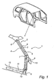
- Fig. 1 shows a part of a vehicle frame structure 1 having an A-pillar 2.
- the A-pillar has an interior cavity 3, in this case in the form of an elongated section, adapted to receive at least one inflatable reinforcement element 4 according to a first embodiment of the invention.
- the cavity is defined by cavity wall portions 5 in which the tubular element is received.
- the element 4 is preferably a tubular element 4 which is fastened in a first end portion 6 and a second end portion 7 of the cavity 3. However, at least one end of the tubular element 4 may extend outside the cavity 3. Additional tubular elements may be arranged in the vehicle at different locations, as exemplified in fig 1 .
- the tubular element 4 in fig. 1 is preferably adapted to reinforce the frame structure 1 in the longitudinal direction between the first end portion 6 and second end portion 7.
- the tubular element 4 in fig. 1 has an essentially circular cross section having a flexible wall portion 8 in an un-active and unpressurized state.
- the wall portion 8 is preferably rigid to such an extent that the element will not be bend and doubled when mounting the element. Preferably, slighter adjustments may be made for easier introduction into the cavity, when mounting the element.
- the tubular element 4 is in fluid connection with a gas generator 9 for pressurizing the element in an active state.
- the gas generation may be achieved in different ways.
- the gas may be generated from gas chambers filled with compressed gases.
- the gases may be: inert gases, such as at least one of the gases; Ar, He or N2 or combustible gases such as one of the gases H2, CH4, C2H6 or C3H8; or any mixtures thereof.
- the gas may be generated from pyrotechnic charges.
- pyrotechnic cords (not shown) may be arranged interiorly the tubular element 4 for pressurization.
- the tubular element preferably comprises a reinforcement material.
- the pressure is preferably above 5 bar and preferably between 5-100 bar, more preferably between 20-70 bar and most preferably between 30-50 bar.
- a ventilation arrangement (not shown) may be arranged in connection with the tubular element.
- the ventilation arrangement may be a burst disc adapted to burst at a predetermined gas pressure or alternatively a mechanical valve which for instance may be spring biased.
- the tubular element may comprise an armoured polymer tube or a metal mantle.
- the reinforcement material may be of different material, designs and forms, such as one of a cord, sheet, fibre, net, weave material portion or a combination thereof.
- the tubular element may comprise one of the following reinforcement layers; glass fibre, metal net, thin steel sheet material or metal cord material. Additionally the tubular element may comprise at least two layers for improving reinforcement or self-stiffening properties.
- Fig. 1 shows that the gas generator 9 may be fitted with an initiator 10 which is connected to a control unit 11, such as an electrical processing unit (EPU) for activating the pressurization in the tubular element.
- the control unit 11 may in turn and alternatively instead be connected to a pre-crash system 12.
- the pre-crash system 12 may comprise a set of sensors arranged at different locations at the vehicle in order to determine which type of crash the vehicle is about to be subjected to.
- sensors may be at least one of the following; a distance sensor, a decelerate sensor and a radar device.
- Fig. 2a shows an alternative reinforcement element 24 according to a second embodiment of the invention to achieve an essentially diagonal reinforcement.
- the tubular element 24 is preferably zigzag shaped but other forms may be used such as an helical shape.
- the dotted line in fig. 2a shows a main centre line along the length extension, wherein the tubular element has transverse extensions 25 directed transversely the main centre line.
- the transverse extensions 25 is preferably slightly bevelled for achieving a smooth contact with the cavity wall 5 and improving the reinforcement characteristics.
- the transverse extensions 25 withstand stresses in the longitudinal direction of the wall portions 8 which are diverging according to the second embodiment.
- the form of the tubular element in relation to the vehicle structure may provide a selected load take-up and a reinforcement in additional directions, such as a combination of a longitudinal and a transversal direction.
- Fig. 2b shows an alternative reinforcement element 34 according to a third embodiment of the invention to achieve a combination of an essentially longitudinal and a transversal reinforcement.
- the tubular element 34 has transversal extensions in the form of transversal protrusions 30, preferably skeleton shaped.
- the protrusions 30 is essentially orthogonally arranged to the main centreline.
- the protrusions 30 is preferably oppositely arranged to contact the cavity wall 5 for improving the reinforcement characteristics.
- the protrusions may be arranged differently at the tubular element, such as unevenly distributed along the longitudinal and / or circumferential direction.
- the control unit 11 may be activated and the initiator 10 can ignites the gas generant material.
- the gas generator 9 discharges the gas into the tubular element via a gas diffuser (not shown) for pressurization. Due to the reinforcement layer the pressurization may be performed with hardly no significant circumferential expansion.
- the tubular element is pressurized without any substantial size expansion.
- the volume of the tubular element in said pressurized state is preferably less than 100% of the entire volume.
- the volume of the tubular element in said pressurized state is preferably under 90% of the entire cavity volume, more preferably under 75% and most preferably under 50% of the entire cavity volume.
- tubular element may be selected to provide a desired particular reinforcing performance in a certain application.
- the tubular element preferably contacting the cavity wall portion without filling up the entire cavity volume.
- the vehicle frame structure 1 may be provided with a set of tubular elements which elements may be activated in sequence or activated with a predetermined delay.
- a in-crash system may be used in addition or alternatively instead of the pre-crash system.
- the in-crash system is preferably arranged with a sensor system as known in the art.
- gas generating devices other ways are possible of pyrotechnic and non-pyrotechnic solutions with or without premixing chambers. It is also possible to combine different gas generating constructions.
- the cavity 3 may be provided with at least two reinforcement elements which may have different reinforcing properties. Additionally the reinforcement element may be arranged in different beams and profiles.
- a profile may be arranged with a tubular element which is held in place at the profile, for instance by transversal bridging elements which at least partly encircles the circumferential wall portion of the tubular elements.
- a front and / or a rear bumper may be provided with at least one reinforcement element according to the invention.
- the bumber seen as a beam, may be arranged with a set of tubular elements.
- the tubular elements can be activated essentially simultaneously or alternatively a selected set may be activated, for instance in a sequence.
- the set may be arranged in a honeycomb structure for an efficient stress up-taking ability.
- Associated beams to the bumper may also be provided with reinforcement elements.
Landscapes
- Engineering & Computer Science (AREA)
- Chemical & Material Sciences (AREA)
- Combustion & Propulsion (AREA)
- Transportation (AREA)
- Mechanical Engineering (AREA)
- Body Structure For Vehicles (AREA)
- Silver Salt Photography Or Processing Solution Therefor (AREA)
- Signal Processing For Digital Recording And Reproducing (AREA)
- Regulating Braking Force (AREA)
Claims (13)
- Mit druckbeaufschlagbarem Verstärkungselement (4, 24, 34) versehene Fahrzeugstrukturanordnung, die in Verbindung mit einem Fahrzeugstrukturprofil (2) zur Verstärkung des Profils bereitgestellt ist, wobei das Verstärkungselement (4, 24, 34) dafür eingerichtet ist, infolge der Art des Aufpralls selektiv aktiviert zu werden, und wobei das Fahrzeugstrukturprofil ein Holm ist und einen Innenraum aufweist und das Verstärkungselement (4, 24, 34) mindestens teilweise im Innenraum (3) des Holmes angeordnet ist,
dadurch gekennzeichnet, dass das Verstärkungselement ein röhrenförmiges Element (4, 24, 34) ist, das eine Schicht aus Verstärkungsmaterial umfasst und einen flexiblen Wandungsabschnitt (8) aufweist, wobei das röhrenförmige Element dafür eingerichtet ist, sich von selbst zu versteifen, wenn es sich in einem druckbeaufschlagten aktiven Zustand befindet, wobei das Material und die Abmessung des Wandungsabschnitts (8) des röhrenförmigen Elements dafür eingerichtet sind, effektiven Beanspruchungen in Längsrichtung des Wandungsabschnittes (8) in diesem druckbeaufschlagten aktiven Zustand standzuhalten. - Anordnung nach Anspruch 1, wobei das Fahrzeugstrukturprofil eine Säule ist.
- Anordnung nach Anspruch 2, wobei sich das röhrenförmige Element (4, 24, 34) im druckbeaufschlagten aktiven Zustand ohne Auffüllen des Innenraumes (3) des Holmes selbst versteift.
- Anordnung nach Anspruch 3, wobei der Wandungsabschnitt (8) des röhrenförmigen Elements (4, 24, 34) derart angeordnet ist, dass er gegenüberliegende Wandungsabschnitte (5) des Holmes (2) berührt.
- Anordnung nach einem der vorhergehenden Ansprüche, wobei die Erstreckung des röhrenförmigen Elements (4, 24, 34) derart an die Erstreckung des Fahrzeugstrukturprofils (2) angepasst ist, dass die Verstärkung in mindestens eine festgelegte Richtung gebildet wird.
- Anordnung nach Anspruch 5, wobei das röhrenförmige Element dafür eingerichtet ist, im druckbeaufschlagten aktiven Zustand in der vorbestimmten Richtung mindestens eine der folgenden Verstärkungen aufzuweisen: eine Längsverstärkung, eine Diagonalverstärkung, eine Querverstärkung und eine Verstärkung orthogonal zur Längserstreckung.
- Anordnung nach einem der vorhergehenden Ansprüche, wobei das Fahrzeugstrukturprofil entlang der Längserstreckung eine Hauptmittellinie aufweist, wobei das röhrenförmige Element (24, 34) mindestens eine Quererstreckung (25, 30) aufweist, die quer zur Hauptmittellinie ausgerichtet ist.
- Anordnung nach einem der vorhergehenden Ansprüche, wobei das röhrenförmige Element (4, 24, 34) zwischen einem ersten Endabschnitt (6) und einem zweiten Endabschnitt (7) des Holmes (2) angeordnet ist.
- Anordnung nach einem der vorhergehenden Ansprüche, wobei die Schicht aus Verstärkungsmaterial entweder ein Glasfasermaterial, ein dünnes Metallmaterial, ein Kohlefasermaterial, ein Material aus verkettetem Polymer, ein Rovinggewebematerial oder Kombinationen daraus ist.
- Anordnung nach einem der vorhergehenden Ansprüche, wobei der Wandungsabschnitt (8) des röhrenförmigen Elements (4, 24, 34) mindestens zwei Schichten umfasst.
- Anordnung nach einem der vorhergehenden Ansprüche, wobei das Fahrzeugstrukturprofil (2) eine A-Säule und/oder eine B-Säule ist.
- Anordnung nach einem der Ansprüche 1 bis 10, wobei das Fahrzeugstrukturprofil ein vorderer Stoßfänger und/oder ein hinterer Stoßfänger ist.
- Anordnung nach einem der vorhergehenden Ansprüche, wobei das Fahrzeugstrukturprofil mindestens zwei röhrenförmige Elemente (4, 24, 34) umfasst, die dafür angeordnet sind, unabhängig voneinander druckbeaufschlagt zu werden.
Applications Claiming Priority (1)
| Application Number | Priority Date | Filing Date | Title |
|---|---|---|---|
| PCT/SE2006/000700 WO2007145547A1 (en) | 2006-06-14 | 2006-06-14 | Vehicle structure arrangement provided with pressurizable reinforcement element |
Publications (2)
| Publication Number | Publication Date |
|---|---|
| EP2027006A1 EP2027006A1 (de) | 2009-02-25 |
| EP2027006B1 true EP2027006B1 (de) | 2010-02-03 |
Family
ID=38831971
Family Applications (1)
| Application Number | Title | Priority Date | Filing Date |
|---|---|---|---|
| EP06747893A Not-in-force EP2027006B1 (de) | 2006-06-14 | 2006-06-14 | Mit druckbeaufschlagbarem verstärkungselement versehene fahrzeugstrukturanordnung |
Country Status (6)
| Country | Link |
|---|---|
| US (1) | US8215674B2 (de) |
| EP (1) | EP2027006B1 (de) |
| JP (1) | JP2009539698A (de) |
| AT (1) | ATE457005T1 (de) |
| DE (1) | DE602006012128D1 (de) |
| WO (1) | WO2007145547A1 (de) |
Cited By (1)
| Publication number | Priority date | Publication date | Assignee | Title |
|---|---|---|---|---|
| DE102016122873A1 (de) * | 2016-11-28 | 2018-05-30 | Dr. Ing. H.C. F. Porsche Aktiengesellschaft | Positioniervorrichtung |
Families Citing this family (10)
| Publication number | Priority date | Publication date | Assignee | Title |
|---|---|---|---|---|
| US8256829B2 (en) * | 2004-04-02 | 2012-09-04 | GM Global Technology Operations LLC | Active material inserts for use with hollow structures |
| US8733819B1 (en) | 2013-01-22 | 2014-05-27 | Ford Global Technologies, Llc | Variable stiffness energy-absorbing component for vehicle occupant protection |
| US9731768B2 (en) * | 2015-03-27 | 2017-08-15 | Ford Global Technologies, Llc | Vehicle structural reinforcing device |
| DE102017200368A1 (de) * | 2017-01-11 | 2018-07-12 | Bayerische Motoren Werke Aktiengesellschaft | Spriegel eines Kraftfahrzeugs |
| JP6805999B2 (ja) * | 2017-08-10 | 2020-12-23 | 豊田合成株式会社 | 車両用支柱部の剛性可変構造 |
| US20190071050A1 (en) * | 2017-09-06 | 2019-03-07 | Ford Global Technologies, Llc | Vehicle airbag system |
| JP6927059B2 (ja) | 2018-01-18 | 2021-08-25 | トヨタ自動車株式会社 | 車両用シート |
| JP6927058B2 (ja) | 2018-01-18 | 2021-08-25 | トヨタ自動車株式会社 | 車両用シート |
| JP6921137B2 (ja) * | 2019-03-11 | 2021-08-18 | 本田技研工業株式会社 | 車両前部構造 |
| US11136065B2 (en) * | 2020-02-24 | 2021-10-05 | Ford Global Technologies, Llc | Extended roof reinforcement structure |
Family Cites Families (15)
| Publication number | Priority date | Publication date | Assignee | Title |
|---|---|---|---|---|
| DE2364300A1 (de) | 1973-12-22 | 1975-06-26 | Porsche Ag | Vorrichtung zur energieabsorption fuer fahrzeuge, insbesondere kraftfahrzeuge |
| US5382051A (en) * | 1991-08-28 | 1995-01-17 | Concept Analysis Corporation | Pneumatic pads for the interior of vehicles |
| US5727815A (en) * | 1996-02-09 | 1998-03-17 | Morton International, Inc. | Stiffening system for structural member of motor vehicle frame |
| US5845937A (en) * | 1997-02-10 | 1998-12-08 | Morton International, Inc. | Structural assembly |
| US6334639B1 (en) * | 1998-07-09 | 2002-01-01 | Giat Industries | Bumper equipped with shock-absorbing means |
| US6113178A (en) * | 1998-08-31 | 2000-09-05 | Trw Vehicle Safety Systems Inc. | Vehicle energy absorption apparatus |
| JP3496751B2 (ja) * | 1999-01-29 | 2004-02-16 | マツダ株式会社 | 自動車の車体構造 |
| GB2354979A (en) | 1999-10-09 | 2001-04-11 | Ford Global Tech Inc | Collapsible vehicle side members having airbags within |
| DE19963068C5 (de) | 1999-12-24 | 2011-05-12 | Dr. Ing. H.C. F. Porsche Aktiengesellschaft | Einrichtung für bei Aufprallunfällen energieumwandelnd-verformbare Karosseriebereiche von Kraftfahrzeugen |
| US20020175537A1 (en) | 2001-04-02 | 2002-11-28 | Cress Steven B. | Vehicle strengthening method and apparatus |
| JP4306229B2 (ja) * | 2002-04-03 | 2009-07-29 | タカタ株式会社 | 衝突検出装置及び安全装置 |
| JP2005035403A (ja) * | 2003-07-15 | 2005-02-10 | Toyota Motor Corp | 車両の耐衝撃構造 |
| US7232002B2 (en) * | 2003-07-18 | 2007-06-19 | University Of Washington | Apparatus for controlling rigidity of vehicle body |
| GB2422645B (en) * | 2005-02-01 | 2009-05-13 | Autoliv Dev | Improvements in or relating to a safety arrangement |
| KR101033790B1 (ko) * | 2008-12-04 | 2011-05-13 | 기아자동차주식회사 | 차량용 외장 에어백 시스템 |
-
2006
- 2006-06-14 AT AT06747893T patent/ATE457005T1/de not_active IP Right Cessation
- 2006-06-14 JP JP2009515330A patent/JP2009539698A/ja active Pending
- 2006-06-14 DE DE602006012128T patent/DE602006012128D1/de active Active
- 2006-06-14 US US12/304,199 patent/US8215674B2/en not_active Expired - Fee Related
- 2006-06-14 EP EP06747893A patent/EP2027006B1/de not_active Not-in-force
- 2006-06-14 WO PCT/SE2006/000700 patent/WO2007145547A1/en not_active Ceased
Cited By (2)
| Publication number | Priority date | Publication date | Assignee | Title |
|---|---|---|---|---|
| DE102016122873A1 (de) * | 2016-11-28 | 2018-05-30 | Dr. Ing. H.C. F. Porsche Aktiengesellschaft | Positioniervorrichtung |
| DE102016122873B4 (de) * | 2016-11-28 | 2025-01-16 | Dr. Ing. H.C. F. Porsche Aktiengesellschaft | Positioniervorrichtung |
Also Published As
| Publication number | Publication date |
|---|---|
| WO2007145547A1 (en) | 2007-12-21 |
| US8215674B2 (en) | 2012-07-10 |
| EP2027006A1 (de) | 2009-02-25 |
| DE602006012128D1 (de) | 2010-03-25 |
| ATE457005T1 (de) | 2010-02-15 |
| JP2009539698A (ja) | 2009-11-19 |
| US20090267386A1 (en) | 2009-10-29 |
Similar Documents
| Publication | Publication Date | Title |
|---|---|---|
| KR100256432B1 (ko) | 차량의 측면 충격으로부터 승객을 보호하기 위한 안전장치 및 방법 | |
| CA2193371C (en) | Inflatable tubular cushions for seated occupants | |
| US8215674B2 (en) | Vehicle structure arrangement provided with pressurizable reinforcement element | |
| CN101790468A (zh) | 用于车辆座椅的结构 | |
| US7891726B2 (en) | Energy absorption body, apparatus for protection against impact, vehicle inner trim part and cross support | |
| US20100276918A1 (en) | Support Structure for an Airbag | |
| US4664438A (en) | Deformable berth for vehicle cabs | |
| US6020039A (en) | Automobile door impact beam | |
| US6176511B1 (en) | Air bag module | |
| GB2293354A (en) | Vehicle body structure | |
| US4273359A (en) | Deformation member arranged in the impact area of the knee | |
| US20060175848A1 (en) | Impact energy absorbing crash cushion | |
| US7497504B2 (en) | Side-on collision beam for a motor vehicle | |
| US7441832B2 (en) | Pneumatically reinforced vehicle body structure | |
| EP1359062A1 (de) | Luftsackmodul | |
| KR20080006539A (ko) | 충돌에 의해 유발되고 차량 도어를 향해 지향된 에너지입력시 차량에서의 승객 보호장치 | |
| US7458608B2 (en) | Vehicle rollover protection system with a roll bar, whose top piece is rounded in U-shape | |
| KR20090017578A (ko) | 가압가능한 보강 요소가 제공된 차량 구조물 장치 | |
| EP1951557B1 (de) | Sicherheitssystem | |
| JP2005035403A (ja) | 車両の耐衝撃構造 | |
| EP1440867B1 (de) | Entwurf-Strukturbauteil für Kraftfahrzeug | |
| US20040100081A1 (en) | Passive protection device and vehicle equipped therewith | |
| US20060208467A1 (en) | Head impact energy-absorbing inflatable curtain gas delivery tube | |
| JP2003341458A (ja) | エアバッグドアの開放構造 | |
| EP4624296A1 (de) | Verbesserter airbag, insbesondere für ein fahrzeug |
Legal Events
| Date | Code | Title | Description |
|---|---|---|---|
| PUAI | Public reference made under article 153(3) epc to a published international application that has entered the european phase |
Free format text: ORIGINAL CODE: 0009012 |
|
| 17P | Request for examination filed |
Effective date: 20081117 |
|
| AK | Designated contracting states |
Kind code of ref document: A1 Designated state(s): AT BE BG CH CY CZ DE DK EE ES FI FR GB GR HU IE IS IT LI LT LU LV MC NL PL PT RO SE SI SK TR |
|
| AX | Request for extension of the european patent |
Extension state: AL BA HR MK RS |
|
| RIN1 | Information on inventor provided before grant (corrected) |
Inventor name: PERSSON, DAN |
|
| RIC1 | Information provided on ipc code assigned before grant |
Ipc: B62D 21/16 20060101ALI20090519BHEP Ipc: B60R 19/18 20060101ALI20090519BHEP Ipc: B62D 21/15 20060101AFI20080228BHEP Ipc: B62D 25/04 20060101ALI20090519BHEP |
|
| 17Q | First examination report despatched |
Effective date: 20090715 |
|
| GRAP | Despatch of communication of intention to grant a patent |
Free format text: ORIGINAL CODE: EPIDOSNIGR1 |
|
| DAX | Request for extension of the european patent (deleted) | ||
| GRAS | Grant fee paid |
Free format text: ORIGINAL CODE: EPIDOSNIGR3 |
|
| GRAA | (expected) grant |
Free format text: ORIGINAL CODE: 0009210 |
|
| AK | Designated contracting states |
Kind code of ref document: B1 Designated state(s): AT BE BG CH CY CZ DE DK EE ES FI FR GB GR HU IE IS IT LI LT LU LV MC NL PL PT RO SE SI SK TR |
|
| REG | Reference to a national code |
Ref country code: GB Ref legal event code: FG4D |
|
| REG | Reference to a national code |
Ref country code: CH Ref legal event code: EP |
|
| REG | Reference to a national code |
Ref country code: IE Ref legal event code: FG4D |
|
| REF | Corresponds to: |
Ref document number: 602006012128 Country of ref document: DE Date of ref document: 20100325 Kind code of ref document: P |
|
| REG | Reference to a national code |
Ref country code: NL Ref legal event code: VDEP Effective date: 20100203 |
|
| LTIE | Lt: invalidation of european patent or patent extension |
Effective date: 20100203 |
|
| PG25 | Lapsed in a contracting state [announced via postgrant information from national office to epo] |
Ref country code: IS Free format text: LAPSE BECAUSE OF FAILURE TO SUBMIT A TRANSLATION OF THE DESCRIPTION OR TO PAY THE FEE WITHIN THE PRESCRIBED TIME-LIMIT Effective date: 20100603 Ref country code: LT Free format text: LAPSE BECAUSE OF FAILURE TO SUBMIT A TRANSLATION OF THE DESCRIPTION OR TO PAY THE FEE WITHIN THE PRESCRIBED TIME-LIMIT Effective date: 20100203 Ref country code: ES Free format text: LAPSE BECAUSE OF FAILURE TO SUBMIT A TRANSLATION OF THE DESCRIPTION OR TO PAY THE FEE WITHIN THE PRESCRIBED TIME-LIMIT Effective date: 20100514 Ref country code: PT Free format text: LAPSE BECAUSE OF FAILURE TO SUBMIT A TRANSLATION OF THE DESCRIPTION OR TO PAY THE FEE WITHIN THE PRESCRIBED TIME-LIMIT Effective date: 20100603 |
|
| PG25 | Lapsed in a contracting state [announced via postgrant information from national office to epo] |
Ref country code: PL Free format text: LAPSE BECAUSE OF FAILURE TO SUBMIT A TRANSLATION OF THE DESCRIPTION OR TO PAY THE FEE WITHIN THE PRESCRIBED TIME-LIMIT Effective date: 20100203 Ref country code: LV Free format text: LAPSE BECAUSE OF FAILURE TO SUBMIT A TRANSLATION OF THE DESCRIPTION OR TO PAY THE FEE WITHIN THE PRESCRIBED TIME-LIMIT Effective date: 20100203 Ref country code: AT Free format text: LAPSE BECAUSE OF FAILURE TO SUBMIT A TRANSLATION OF THE DESCRIPTION OR TO PAY THE FEE WITHIN THE PRESCRIBED TIME-LIMIT Effective date: 20100203 Ref country code: SI Free format text: LAPSE BECAUSE OF FAILURE TO SUBMIT A TRANSLATION OF THE DESCRIPTION OR TO PAY THE FEE WITHIN THE PRESCRIBED TIME-LIMIT Effective date: 20100203 Ref country code: FI Free format text: LAPSE BECAUSE OF FAILURE TO SUBMIT A TRANSLATION OF THE DESCRIPTION OR TO PAY THE FEE WITHIN THE PRESCRIBED TIME-LIMIT Effective date: 20100203 |
|
| PG25 | Lapsed in a contracting state [announced via postgrant information from national office to epo] |
Ref country code: GR Free format text: LAPSE BECAUSE OF FAILURE TO SUBMIT A TRANSLATION OF THE DESCRIPTION OR TO PAY THE FEE WITHIN THE PRESCRIBED TIME-LIMIT Effective date: 20100504 Ref country code: NL Free format text: LAPSE BECAUSE OF FAILURE TO SUBMIT A TRANSLATION OF THE DESCRIPTION OR TO PAY THE FEE WITHIN THE PRESCRIBED TIME-LIMIT Effective date: 20100203 Ref country code: SE Free format text: LAPSE BECAUSE OF FAILURE TO SUBMIT A TRANSLATION OF THE DESCRIPTION OR TO PAY THE FEE WITHIN THE PRESCRIBED TIME-LIMIT Effective date: 20100203 Ref country code: RO Free format text: LAPSE BECAUSE OF FAILURE TO SUBMIT A TRANSLATION OF THE DESCRIPTION OR TO PAY THE FEE WITHIN THE PRESCRIBED TIME-LIMIT Effective date: 20100203 Ref country code: CY Free format text: LAPSE BECAUSE OF FAILURE TO SUBMIT A TRANSLATION OF THE DESCRIPTION OR TO PAY THE FEE WITHIN THE PRESCRIBED TIME-LIMIT Effective date: 20100203 Ref country code: EE Free format text: LAPSE BECAUSE OF FAILURE TO SUBMIT A TRANSLATION OF THE DESCRIPTION OR TO PAY THE FEE WITHIN THE PRESCRIBED TIME-LIMIT Effective date: 20100203 Ref country code: BE Free format text: LAPSE BECAUSE OF FAILURE TO SUBMIT A TRANSLATION OF THE DESCRIPTION OR TO PAY THE FEE WITHIN THE PRESCRIBED TIME-LIMIT Effective date: 20100203 |
|
| PG25 | Lapsed in a contracting state [announced via postgrant information from national office to epo] |
Ref country code: CZ Free format text: LAPSE BECAUSE OF FAILURE TO SUBMIT A TRANSLATION OF THE DESCRIPTION OR TO PAY THE FEE WITHIN THE PRESCRIBED TIME-LIMIT Effective date: 20100203 Ref country code: BG Free format text: LAPSE BECAUSE OF FAILURE TO SUBMIT A TRANSLATION OF THE DESCRIPTION OR TO PAY THE FEE WITHIN THE PRESCRIBED TIME-LIMIT Effective date: 20100503 Ref country code: SK Free format text: LAPSE BECAUSE OF FAILURE TO SUBMIT A TRANSLATION OF THE DESCRIPTION OR TO PAY THE FEE WITHIN THE PRESCRIBED TIME-LIMIT Effective date: 20100203 |
|
| PLBE | No opposition filed within time limit |
Free format text: ORIGINAL CODE: 0009261 |
|
| STAA | Information on the status of an ep patent application or granted ep patent |
Free format text: STATUS: NO OPPOSITION FILED WITHIN TIME LIMIT |
|
| 26N | No opposition filed |
Effective date: 20101104 |
|
| PG25 | Lapsed in a contracting state [announced via postgrant information from national office to epo] |
Ref country code: DK Free format text: LAPSE BECAUSE OF FAILURE TO SUBMIT A TRANSLATION OF THE DESCRIPTION OR TO PAY THE FEE WITHIN THE PRESCRIBED TIME-LIMIT Effective date: 20100203 Ref country code: MC Free format text: LAPSE BECAUSE OF NON-PAYMENT OF DUE FEES Effective date: 20100630 |
|
| REG | Reference to a national code |
Ref country code: CH Ref legal event code: PL |
|
| GBPC | Gb: european patent ceased through non-payment of renewal fee |
Effective date: 20100614 |
|
| PG25 | Lapsed in a contracting state [announced via postgrant information from national office to epo] |
Ref country code: IT Free format text: LAPSE BECAUSE OF FAILURE TO SUBMIT A TRANSLATION OF THE DESCRIPTION OR TO PAY THE FEE WITHIN THE PRESCRIBED TIME-LIMIT Effective date: 20100203 |
|
| PG25 | Lapsed in a contracting state [announced via postgrant information from national office to epo] |
Ref country code: LI Free format text: LAPSE BECAUSE OF NON-PAYMENT OF DUE FEES Effective date: 20100630 Ref country code: CH Free format text: LAPSE BECAUSE OF NON-PAYMENT OF DUE FEES Effective date: 20100630 Ref country code: IE Free format text: LAPSE BECAUSE OF NON-PAYMENT OF DUE FEES Effective date: 20100614 |
|
| PG25 | Lapsed in a contracting state [announced via postgrant information from national office to epo] |
Ref country code: GB Free format text: LAPSE BECAUSE OF NON-PAYMENT OF DUE FEES Effective date: 20100614 |
|
| PG25 | Lapsed in a contracting state [announced via postgrant information from national office to epo] |
Ref country code: HU Free format text: LAPSE BECAUSE OF FAILURE TO SUBMIT A TRANSLATION OF THE DESCRIPTION OR TO PAY THE FEE WITHIN THE PRESCRIBED TIME-LIMIT Effective date: 20100804 Ref country code: LU Free format text: LAPSE BECAUSE OF NON-PAYMENT OF DUE FEES Effective date: 20100614 |
|
| PG25 | Lapsed in a contracting state [announced via postgrant information from national office to epo] |
Ref country code: TR Free format text: LAPSE BECAUSE OF FAILURE TO SUBMIT A TRANSLATION OF THE DESCRIPTION OR TO PAY THE FEE WITHIN THE PRESCRIBED TIME-LIMIT Effective date: 20100203 |
|
| REG | Reference to a national code |
Ref country code: FR Ref legal event code: PLFP Year of fee payment: 10 |
|
| PGFP | Annual fee paid to national office [announced via postgrant information from national office to epo] |
Ref country code: DE Payment date: 20150413 Year of fee payment: 10 |
|
| PGFP | Annual fee paid to national office [announced via postgrant information from national office to epo] |
Ref country code: FR Payment date: 20150406 Year of fee payment: 10 |
|
| REG | Reference to a national code |
Ref country code: DE Ref legal event code: R119 Ref document number: 602006012128 Country of ref document: DE |
|
| REG | Reference to a national code |
Ref country code: FR Ref legal event code: ST Effective date: 20170228 |
|
| PG25 | Lapsed in a contracting state [announced via postgrant information from national office to epo] |
Ref country code: FR Free format text: LAPSE BECAUSE OF NON-PAYMENT OF DUE FEES Effective date: 20160630 Ref country code: DE Free format text: LAPSE BECAUSE OF NON-PAYMENT OF DUE FEES Effective date: 20170103 |