EP2027973A2 - Wechselbare Werkzeugaufnahme - Google Patents
Wechselbare Werkzeugaufnahme Download PDFInfo
- Publication number
- EP2027973A2 EP2027973A2 EP08104779A EP08104779A EP2027973A2 EP 2027973 A2 EP2027973 A2 EP 2027973A2 EP 08104779 A EP08104779 A EP 08104779A EP 08104779 A EP08104779 A EP 08104779A EP 2027973 A2 EP2027973 A2 EP 2027973A2
- Authority
- EP
- European Patent Office
- Prior art keywords
- tool holder
- tool
- locking
- unlocking
- sleeve
- Prior art date
- Legal status (The legal status is an assumption and is not a legal conclusion. Google has not performed a legal analysis and makes no representation as to the accuracy of the status listed.)
- Withdrawn
Links
- 238000006073 displacement reaction Methods 0.000 claims abstract description 13
- 238000011161 development Methods 0.000 claims description 4
- 230000005284 excitation Effects 0.000 description 5
- 230000018109 developmental process Effects 0.000 description 3
- 230000001404 mediated effect Effects 0.000 description 2
- 238000010009 beating Methods 0.000 description 1
- 238000001746 injection moulding Methods 0.000 description 1
- 238000009527 percussion Methods 0.000 description 1
- 230000002787 reinforcement Effects 0.000 description 1
Images

Classifications
-
- B—PERFORMING OPERATIONS; TRANSPORTING
- B25—HAND TOOLS; PORTABLE POWER-DRIVEN TOOLS; MANIPULATORS
- B25D—PERCUSSIVE TOOLS
- B25D17/00—Details of, or accessories for, portable power-driven percussive tools
- B25D17/08—Means for retaining and guiding the tool bit, e.g. chucks allowing axial oscillation of the tool bit
- B25D17/084—Rotating chucks or sockets
- B25D17/088—Rotating chucks or sockets with radial movable locking elements co-operating with bit shafts specially adapted therefor
-
- B—PERFORMING OPERATIONS; TRANSPORTING
- B23—MACHINE TOOLS; METAL-WORKING NOT OTHERWISE PROVIDED FOR
- B23Q—DETAILS, COMPONENTS, OR ACCESSORIES FOR MACHINE TOOLS, e.g. ARRANGEMENTS FOR COPYING OR CONTROLLING; MACHINE TOOLS IN GENERAL CHARACTERISED BY THE CONSTRUCTION OF PARTICULAR DETAILS OR COMPONENTS; COMBINATIONS OR ASSOCIATIONS OF METAL-WORKING MACHINES, NOT DIRECTED TO A PARTICULAR RESULT
- B23Q3/00—Devices holding, supporting, or positioning work or tools, of a kind normally removable from the machine
- B23Q3/12—Devices holding, supporting, or positioning work or tools, of a kind normally removable from the machine for securing to a spindle in general
-
- B—PERFORMING OPERATIONS; TRANSPORTING
- B25—HAND TOOLS; PORTABLE POWER-DRIVEN TOOLS; MANIPULATORS
- B25D—PERCUSSIVE TOOLS
- B25D2250/00—General details of portable percussive tools; Components used in portable percussive tools
- B25D2250/231—Sleeve details
- B25D2250/235—Sleeve couplings
-
- B—PERFORMING OPERATIONS; TRANSPORTING
- B25—HAND TOOLS; PORTABLE POWER-DRIVEN TOOLS; MANIPULATORS
- B25D—PERCUSSIVE TOOLS
- B25D2250/00—General details of portable percussive tools; Components used in portable percussive tools
- B25D2250/325—Use of bayonets
-
- Y—GENERAL TAGGING OF NEW TECHNOLOGICAL DEVELOPMENTS; GENERAL TAGGING OF CROSS-SECTIONAL TECHNOLOGIES SPANNING OVER SEVERAL SECTIONS OF THE IPC; TECHNICAL SUBJECTS COVERED BY FORMER USPC CROSS-REFERENCE ART COLLECTIONS [XRACs] AND DIGESTS
- Y10—TECHNICAL SUBJECTS COVERED BY FORMER USPC
- Y10S—TECHNICAL SUBJECTS COVERED BY FORMER USPC CROSS-REFERENCE ART COLLECTIONS [XRACs] AND DIGESTS
- Y10S279/00—Chucks or sockets
- Y10S279/902—Keyless type socket
-
- Y—GENERAL TAGGING OF NEW TECHNOLOGICAL DEVELOPMENTS; GENERAL TAGGING OF CROSS-SECTIONAL TECHNOLOGIES SPANNING OVER SEVERAL SECTIONS OF THE IPC; TECHNICAL SUBJECTS COVERED BY FORMER USPC CROSS-REFERENCE ART COLLECTIONS [XRACs] AND DIGESTS
- Y10—TECHNICAL SUBJECTS COVERED BY FORMER USPC
- Y10S—TECHNICAL SUBJECTS COVERED BY FORMER USPC CROSS-REFERENCE ART COLLECTIONS [XRACs] AND DIGESTS
- Y10S279/00—Chucks or sockets
- Y10S279/904—Quick change socket
- Y10S279/905—Quick change socket with ball detent
-
- Y—GENERAL TAGGING OF NEW TECHNOLOGICAL DEVELOPMENTS; GENERAL TAGGING OF CROSS-SECTIONAL TECHNOLOGIES SPANNING OVER SEVERAL SECTIONS OF THE IPC; TECHNICAL SUBJECTS COVERED BY FORMER USPC CROSS-REFERENCE ART COLLECTIONS [XRACs] AND DIGESTS
- Y10—TECHNICAL SUBJECTS COVERED BY FORMER USPC
- Y10T—TECHNICAL SUBJECTS COVERED BY FORMER US CLASSIFICATION
- Y10T279/00—Chucks or sockets
- Y10T279/17—Socket type
- Y10T279/17042—Lost motion
-
- Y—GENERAL TAGGING OF NEW TECHNOLOGICAL DEVELOPMENTS; GENERAL TAGGING OF CROSS-SECTIONAL TECHNOLOGIES SPANNING OVER SEVERAL SECTIONS OF THE IPC; TECHNICAL SUBJECTS COVERED BY FORMER USPC CROSS-REFERENCE ART COLLECTIONS [XRACs] AND DIGESTS
- Y10—TECHNICAL SUBJECTS COVERED BY FORMER USPC
- Y10T—TECHNICAL SUBJECTS COVERED BY FORMER US CLASSIFICATION
- Y10T279/00—Chucks or sockets
- Y10T279/17—Socket type
- Y10T279/17666—Radially reciprocating jaws
- Y10T279/17692—Moving-cam actuator
- Y10T279/17743—Reciprocating cam sleeve
- Y10T279/17752—Ball or roller jaws
-
- Y—GENERAL TAGGING OF NEW TECHNOLOGICAL DEVELOPMENTS; GENERAL TAGGING OF CROSS-SECTIONAL TECHNOLOGIES SPANNING OVER SEVERAL SECTIONS OF THE IPC; TECHNICAL SUBJECTS COVERED BY FORMER USPC CROSS-REFERENCE ART COLLECTIONS [XRACs] AND DIGESTS
- Y10—TECHNICAL SUBJECTS COVERED BY FORMER USPC
- Y10T—TECHNICAL SUBJECTS COVERED BY FORMER US CLASSIFICATION
- Y10T279/00—Chucks or sockets
- Y10T279/34—Accessory or component
- Y10T279/3425—Sliding cam chuck actuator
Definitions
- the invention refers to a replaceable tool holder for an at least partially striking hand tool, such as a combination hammer or a chisel hammer.
- Interchangeable tool holders are usually over, by means of a manually displaceable unlocking radially limited displaceable, locking elements such as balls which engage through openings of the main body of the tool holder in associated recesses of the tool spindle, releasably detachable and thus manually connected.
- a manually displaceable tool-side release sleeve for locking the recorded impact tool is present.
- the machine-side unlocking sleeve forms a manually tangentially displaceable rotary lock for the balls by the inner, annular locking means forms a circumferentially radially varying locking link.
- DE102004042465 has a removable tool holder a tool-side unlocking sleeve and a machine side against a spring force manually axially displaceable, machine-side Entriegelungshülse with an internal annular locking means for radially positive locking of the tool holder by means of balls which engage through openings of the main body of the tool holder in associated recesses of the tool spindle.
- the locking of the ball by the resulting inertia forces under impact stress which lead to strong axial vibrations of the Entriegelungshülse, not sure.
- a reinforcement of the machine-side unlocking sleeve biasing spring is limited by the user acceptance.
- the task consists in the realization of a locking on the driving tool spindle even at high impact safely unlocking sleeve.
- an exchangeable tool holder for an at least partially axially striking hand tool at least one against a spring force axially displaceable unlocking sleeve with an internal locking means for radially positive locking of the tool holder by means of locking elements which engage through openings of the main body of the tool holder in associated recesses of the tool spindle, wherein the Entriegelungshülse connected to the locking means has a positive displacement guide with respect to the base body, which has along its Axialersteckung a tangential development.
- the offset guide is designed as a pin-slot guide, wherein a radially projecting pin is positively guided along the contour of a radially recessed or open slot, whereby a robust displacement guide is realized.
- the pin is arranged on a gripping sleeve fixedly connected to the base body, for the unlocking sleeve, which engages at least partially axially inside the unlocking sleeve, which has the associated slot, whereby a technologically simple displacement guide is realized, which can be produced by injection molding.
- the pin is assigned to be L-shaped and mediated in the unlocking by the bias in the axially and tangentially angled slot self-locking, whereby changing the tool holder without further manual effort is possible.
- the grip sleeve radially outside a circumferential finger groove, whereby the grip sleeve is ergonomically gripped by the fingers of the actuating hand to move the tool side adjacent unlocking sleeve relative to this.
- the release sleeve additionally inner tool locking means for locking the recorded impact tool, whereby the handling of the tool holder becomes intuitive by the unlocking of the tool only a partial step (only axial displacement) unlocking the tool holder (axial and subsequent tangential displacement).
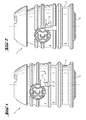
- Fig. 1 has a replaceable tool holder 1 an unlocking sleeve 4, which has a positive displacement guide 5 with respect to the base body 6, which has along its Axialersteckung a tangential development.
- the offset guide 5 is designed as a pin-slot guide, wherein a radially projecting pin 7 is positively guided along the contour of a radially open slot 17.
- the pin 7 is arranged on a fixedly connected to the base body 6, the unlocking sleeve 4 machine side adjacent grip sleeve 8, which engages partially axially in the unlocking sleeve 4 coaxially inside, which has the associated slot 17.
- the grip sleeve 8 has a radially outwardly encircling finger groove 9.
- the pin 7 is associated angularly formed, which is self-locking in the unlocking position mediated by the axial bias in the tangential part of the slot 17.
- Fig. 3 is in the tool holder 1 for a along an axis A on a percussive tool 2 striking hand tool 3, the release sleeve 4 against a spring force of a coil spring 10 axially relative to the grip sleeve 8 displaceable, which is itself firmly connected to the base body 6.
- the unlocking sleeve 4 has an internal annular locking means 11 for radially positive locking of the tool holder 1 by means of locking elements 12 in the form of balls, which are arranged radially displaceable in openings 13 of the body 6 and engage in the locking position in associated recesses 14 of the rotating tool spindle 15.
- the unlocking sleeve 4 has internal tool locking means 16 for a tool locking element 18 in the form of a ball.
- the handling of the tool holder is intuitive in that the unlocking of the impact tool only the partial step of the axial displacement ( Fig. 1 ), wherein for unlocking the tool holder also a subsequent tangential offset is necessary.
Landscapes
- Engineering & Computer Science (AREA)
- Mechanical Engineering (AREA)
- Percussive Tools And Related Accessories (AREA)
- Gripping On Spindles (AREA)
Abstract
Description
- Die Erfindung bezeichnet eine wechselbare Werkzeugaufnahme für eine zumindest teilweise schlagende Handwerkzeugmaschine, wie einen Kombihammer oder einen Meisselhammer.
- Wechselbare Werkzeugaufnahmen sind üblicherweise über, mittels einer von Hand versetzbaren Entriegelungshülse radial begrenzt versetzbare, Verriegelungselemente wie Kugeln, welche durch Öffnungen des Grundkörpers der Werkzeugaufnahme in zugeordnete Ausnehmungen der Werkzeugspindel eingreifen, werkzeuglos lösbar und somit von Hand wechselbar verbunden. Im Inneren der teilweise drehend antreibenden Werkzeugspindel wird der Schläger des Schlagwerks axial begrenzt beweglich geführt, welcher direkt auf das Schlagwerkzeug schlägt. Neben dieser maschinenseitigen Entriegelungshülse ist üblicherweise noch eine von Hand versetzbare werkzeugseitige Entriegelungshülse zur Verriegelung des aufgenommenen Schlagwerkzeugs vorhanden.
- Nach der
US4824298 bildet die maschinenseitige Entriegelungshülse eine händisch tangential versetzbare Drehverriegelung für die Kugeln aus, indem das innenliegende, ringförmige Verriegelungsmittel eine umlaufend radial variierende Verriegelungskulisse ausbildet. - Nach der
DE102004042465 weist eine wechselbare Werkzeugaufnahme eine werkzeugseitige Entriegelungshülse und eine maschinenseitig gegen eine Federkraft händisch axial versetzbare, maschinenseitige Entriegelungshülse mit einem innenliegenden ringförmigen Verriegelungsmittel zur radial formschlüssigen Verriegelung der Werkzeugaufnahme mittels Kugeln auf, welche durch Öffnungen des Grundkörpers der Werkzeugaufnahme in zugeordnete Ausnehmungen der Werkzeugspindel eingreifen. Insbesondere bei leistungsstarken Handwerkzeugmaschinen im Leerschlagfall ist die Verriegelung der Kugel durch die bei schlagender Beanspruchung entstehenden Trägheitskräfte, welche zu starken axialen Vibrationen der Entriegelungshülse führen, nicht sicher gegeben. Eine Verstärkung der die maschinenseitige Entriegelungshülse vorspannenden Feder ist hingegen durch die Nutzerakzeptanz begrenzt. - Die Aufgabe besteht in der Realisierung einer an der antreibenden Werkzeugspindel auch bei hoher Schlagbeanspruchung sicher verriegelnden Entriegelungshülse.
- Die Aufgabe wird im Wesentlichen durch die Merkmale des Anspruchs 1 gelöst. Vorteilhafte Weiterbildungen ergeben sich aus den Unteransprüchen.
- So weist eine wechselbare Werkzeugaufnahme für eine zumindest teilweise axial schlagende Handwerkzeugmaschine zumindest eine gegen eine Federkraft axial versetzbare Entriegelungshülse mit einem innenliegenden Verriegelungsmittel zur radial formschlüssigen Verriegelung der Werkzeugaufnahme mittels Verriegelungselemente auf, welche durch Öffnungen des Grundkörpers der Werkzeugaufnahme in zugeordnete Ausnehmungen der Werkzeugspindel eingreifen, wobei die mit dem Verriegelungsmittel verbundene Entriegelungshülse eine formschlüssige Versetzungsführung bezüglich des Grundkörpers aufweist, welche entlang ihrer Axialersteckung eine tangentiale Abwicklung aufweist.
- Durch die entlang ihrer Axialersteckung eine tangentiale Abwicklung aufweisende Versetzungsführung muss zur Entriegelung der Werkzeugaufnahme die Entriegelungshülse in hintereinander ausgeführten Schritten sowohl axial als auch tangential versetzt werden. Da selbst unter der Annahme einer sowohl drehenden als auch schlagenden stochastischen Vibrationserregung, die ohne Versetzungsführung eine hinreichende Versetzung der Entriegelungshülse von der Verriegelungsposition in die axial und tangential versetzte Entriegelungsposition gestatten würde, reicht diese Vibrationserregung bei einer Versetzungsführung nicht aus, da eine axial und tangential versetzte geradlinige Vibrationserregung durch die Versetzungsführung gedämpft wird. Eine zeitlich benachbarte reine axiale und reine tangentiale Vibrationserregung jeweils hinreichender Versetzung ist hingegen durch die sich aus der statistischen Unabhängigkeit beider Vibrationserregungen ergebende bedingte Wahrscheinlichkeit ausgeschlossen, die praktisch null ist.
- Vorteilhaft ist die Versetzungsführung als Zapfen-Schlitz-Führung ausgebildet, wobei ein radial auskragender Zapfen formschlüssig längs der Kontur eines radial ausgenommenen oder offenen Schlitzes geführt wird, wodurch eine robuste Versetzungsführung realisiert ist.
- Vorteilhaft ist der Zapfen auf einer fest mit dem Grundkörper verbundenen, zur Entriegelungshülse maschinenseitig benachbarten Griffhülse angeordnet, die zumindest teilweise axial in die Entriegelungshülse koaxial innenliegend eingreift, die den zugeordneten Schlitz aufweist, wodurch eine technologisch einfache Versetzungsführung realisiert ist, die spritzgusstechnisch herstellbar ist.
- Vorteilhaft ist der Zapfen zugeordnet L-förmig ausgebildet sowie in der Entriegelungsposition vermittelt durch die Vorspannung in dem axial und tangential abgewinkelten Schlitz selbstarretierend, wodurch das Wechseln der Werkzeugaufnahme ohne weiteren händischen Kraftaufwand möglich ist.
- Vorteilhaft weist die Griffhülse radial aussen eine umlaufende Fingernut auf, wodurch die Griffhülse durch die Finger der betätigenden Hand ergonomisch greifbar ist, um die werkzeugseitig benachbarte Entriegelungshülse gegenüber dieser zu versetzen.
- Vorteilhaft weist die Entriegelungshülse zusätzlich innenliegende Werkzeugverriegelungsmittel zur Verriegelung des aufgenommenen Schlagwerkzeugs auf, wodurch die Handhabung der Werkzeugaufnahme intuitiv wird, indem die Entriegelung des Werkzeugs nur einen Teilschritt (nur axiale Versetzung) der Entriegelung der Werkzeugaufnahme (axiale und anschliessende tangentiale Versetzung) darstellt.
- Die Erfindung wird bezüglich eines vorteilhaften Ausführungsbeispiels näher erläutert mit:
-
Fig. 1 als wechselbare Werkzeugaufnahme in Verriegelungsposition -
Fig. 2 in Entriegelungsposition -
Fig. 3 als Längsschnitt in Entriegelungsposition - Nach
Fig. 1 weist eine wechselbare Werkzeugaufnahme 1 eine Entriegelungshülse 4, welche eine formschlüssige Versetzungsführung 5 bezüglich des Grundkörpers 6 aufweist, welche entlang ihrer Axialersteckung eine tangentiale Abwicklung aufweist. Die Versetzungsführung 5 ist als Zapfen-Schlitz-Führung ausgebildet, wobei ein radial auskragender Zapfen 7 formschlüssig längs der Kontur eines radial offenen Schlitzes 17 geführt wird. Dabei ist der Zapfen 7 auf einer fest mit dem Grundkörper 6 verbundenen, zur Entriegelungshülse 4 maschinenseitig benachbarten Griffhülse 8 angeordnet, die teilweise axial in die Entriegelungshülse 4 koaxial innenliegend eingreift, welche den zugeordneten Schlitz 17 aufweist. Weiter weist die Griffhülse 8 eine radial aussen umlaufende Fingernut 9 auf. - Nach
Fig. 2 ist der Zapfen 7 zugeordnet winkelförmig ausgebildet, der in der Entriegelungsposition vermittelt durch die axiale Vorspannung in dem tangentialen Teil des Schlitzes 17 selbstarretierend ist. - Nach
Fig. 3 ist bei der Werkzeugaufnahme 1 für eine längs einer Achse A auf ein Schlagwerkzeug 2 schlagende Handwerkzeugmaschine 3 die Entriegelungshülse 4 gegen eine Federkraft einer Schraubenfeder 10 axial bezüglich der Griffhülse 8 versetzbar, welche selbst fest mit dem Grundkörper 6 verbunden ist. Die Entriegelungshülse 4 weist ein innenliegendes ringförmiges Verriegelungsmittel 11 zur radial formschlüssigen Verriegelung der Werkzeugaufnahme 1 mittels Verriegelungselementen 12 in Form von Kugeln auf, welche in Öffnungen 13 des Grundkörpers 6 radial versetzbar angeordnet sind und in der Verriegelungsposition in zugeordnete Ausnehmungen 14 der drehenden Werkzeugspindel 15 eingreifen. Zusätzlich weist die Entriegelungshülse 4 innenliegende Werkzeugverriegelungsmittel 16 für ein Werkzeugverriegelungselement 18 in Form einer Kugel auf. - Die Handhabung der Werkzeugaufnahme ist intuitiv, indem die Entriegelung des Schlagwerkzeugs nur den Teilschritt der axialen Versetzung (
Fig. 1 ) umfasst, wobei zur Entriegelung der Werkzeugaufnahme zudem eine anschliessende tangentiale Versetzung notwendig ist.
Claims (6)
- Wechselbare Werkzeugaufnahme für eine zumindest teilweise axial schlagende Handwerkzeugmaschine (3) mit zumindest einer gegen eine Federkraft axial versetzbare Entriegelungshülse (4) mit einem innenliegenden Verriegelungsmittel (11) zur radial formschlüssigen Verriegelung der Werkzeugaufnahme mittels Verriegelungselementen (12), welche durch Öffnungen (13) des Grundkörpers (6) der Werkzeugaufnahme in zugeordnete Ausnehmungen (14) der Werkzeugspindel (15) eingreifen, dadurch gekennzeichnet, dass die Entriegelungshülse (4) eine formschlüssige Versetzungsführung (5) bezüglich des Grundkörpers (6) aufweist, welche entlang ihrer Axialersteckung eine tangentiale Abwicklung aufweist.
- Werkzeugaufnahme nach Anspruch 1, dadurch gekennzeichnet, dass die Versetzungsführung (5) als Zapfen-Schlitz-Führung ausgebildet ist, wobei ein radial auskragender Zapfen (7) formschlüssig längs der Kontur eines Schlitzes (17) geführt wird.
- Werkzeugaufnahme nach Anspruch 2, dadurch gekennzeichnet, dass der Zapfen (7) auf einer fest mit dem Grundkörper (6) verbundenen, zur Entriegelungshülse (4) maschinenseitig benachbarten Griffhülse (8) angeordnet ist, die zumindest teilweise axial in die Entriegelungshülse (4) koaxial innenliegend eingreift, die den zugeordneten Schlitz (17) aufweist.
- Werkzeugaufnahme nach Anspruch 2 oder 3, dadurch gekennzeichnet, dass der Zapfen (7) L-förmig ausgebildet und in der Entriegelungsposition in der Abwinklung des Schlitzes (17) selbstarretierend ist.
- Werkzeugaufnahme nach einem der Ansprüche 1 bis 4, dadurch gekennzeichnet, dass die Griffhülse (8) radial aussen eine umlaufende Fingernut (9) aufweist.
- Werkzeugaufnahme nach einem der Ansprüche 1 bis 5, dadurch gekennzeichnet, dass die Entriegelungshülse (4) zusätzlich innenliegende Werkzeugverriegelungsmittel (16) zur Verriegelung des aufgenommenen Schlagwerkzeugs (2) aufweist.
Applications Claiming Priority (1)
| Application Number | Priority Date | Filing Date | Title |
|---|---|---|---|
| DE102007000453A DE102007000453A1 (de) | 2007-08-20 | 2007-08-20 | Wechselbare Werkzeugaufnahme |
Publications (2)
| Publication Number | Publication Date |
|---|---|
| EP2027973A2 true EP2027973A2 (de) | 2009-02-25 |
| EP2027973A3 EP2027973A3 (de) | 2013-10-23 |
Family
ID=40010562
Family Applications (1)
| Application Number | Title | Priority Date | Filing Date |
|---|---|---|---|
| EP08104779.7A Withdrawn EP2027973A3 (de) | 2007-08-20 | 2008-07-17 | Wechselbare Werkzeugaufnahme |
Country Status (5)
| Country | Link |
|---|---|
| US (1) | US8201835B2 (de) |
| EP (1) | EP2027973A3 (de) |
| JP (1) | JP5301920B2 (de) |
| CN (1) | CN101372042B (de) |
| DE (1) | DE102007000453A1 (de) |
Families Citing this family (18)
| Publication number | Priority date | Publication date | Assignee | Title |
|---|---|---|---|---|
| DE102004036587A1 (de) * | 2004-07-28 | 2006-03-23 | Robert Bosch Gmbh | Aufnahmevorrichtung für eine Werkzeugmaschine mit einem Werkzeughalter sowie Werkzeughalter |
| DE102005000168A1 (de) * | 2005-11-25 | 2007-05-31 | Hilti Ag | Werkzeugaufnahme |
| DE102006059349A1 (de) * | 2006-12-15 | 2008-06-19 | Robert Bosch Gmbh | Elektrohandwerkzeugmaschine mit einem Werkzeugverriegelungssystem |
| DE102009001790B4 (de) * | 2009-03-24 | 2014-01-16 | Hilti Aktiengesellschaft | Befestigungselemente-Magazinstreifen |
| DE102010029609A1 (de) | 2010-06-02 | 2011-12-08 | Hilti Aktiengesellschaft | Staubabweisende Werkzeugbremse, Werkzeugeinführteil, Werkzeugaufnahme, Handwerkzeugmaschine |
| DE102012207651A1 (de) * | 2012-05-08 | 2013-11-14 | Aesculap Ag | Schnellspann-Kupplung |
| DE102013213804A1 (de) | 2012-11-22 | 2014-05-22 | Robert Bosch Gmbh | Werkzeugvorsatz für eine Handwerkzeugmaschine |
| CN105665764B (zh) * | 2016-03-28 | 2018-05-22 | 曲阜市崇德精密机械有限公司 | 一种扭矩刀柄筒夹锁紧装置 |
| EP3338958A1 (de) | 2016-12-23 | 2018-06-27 | HILTI Aktiengesellschaft | Werkzeuggerät |
| WO2018159171A1 (ja) * | 2017-02-28 | 2018-09-07 | 工機ホールディングス株式会社 | 打撃作業機 |
| WO2019183311A1 (en) * | 2018-03-23 | 2019-09-26 | Milwaukee Electric Tool Corporation | Attachment mechanism for a power tool |
| WO2020025288A1 (de) | 2018-07-31 | 2020-02-06 | Inventio Ag | Vorrichtung und ein verfahren zum entfernen eines werkzeugs aus einem werkzeughalter |
| US11980948B2 (en) * | 2019-12-26 | 2024-05-14 | Koki Holdings Co., Ltd. | Rotary tool |
| EP3900882A1 (de) * | 2020-04-21 | 2021-10-27 | Hilti Aktiengesellschaft | Andrückelement für werkzeugmaschine |
| WO2022005929A1 (en) | 2020-07-02 | 2022-01-06 | Milwaukee Electric Tool Corporation | Rotary impact tool having bit holding device |
| JP2023090417A (ja) * | 2021-12-17 | 2023-06-29 | 株式会社マキタ | 電動工具 |
| WO2025117585A1 (en) | 2023-11-30 | 2025-06-05 | Stanley Black & Decker, Inc. | Multi-headed power tool and fastening system for same and systems for fastening heads thereon |
| US12594657B2 (en) | 2023-11-30 | 2026-04-07 | Stanley Black & Decker, Inc. | Multi-headed power tool and systems for fastening heads thereon |
Citations (2)
| Publication number | Priority date | Publication date | Assignee | Title |
|---|---|---|---|---|
| US4824298A (en) | 1986-10-23 | 1989-04-25 | Hilti Aktiengesellschaft | Hand-held tool with detachable tool bit chuck |
| DE102004042465A1 (de) | 2004-09-02 | 2006-03-09 | Robert Bosch Gmbh | Handwerkzeugmaschine mit einer austauschbaren Werkzeugaufnahme |
Family Cites Families (21)
| Publication number | Priority date | Publication date | Assignee | Title |
|---|---|---|---|---|
| US3070380A (en) * | 1958-11-20 | 1962-12-25 | Holmberg Arne | Clamping device |
| GB1195505A (en) * | 1967-07-31 | 1970-06-17 | Hilti Ag | Hammer Drill |
| US3719918A (en) * | 1971-11-04 | 1973-03-06 | Schlumberger Technology Corp | Electrical connector |
| US3985368A (en) * | 1974-11-25 | 1976-10-12 | The Bendix Corporation | Quick-change spindle nose adapter |
| AT377459B (de) * | 1981-06-29 | 1985-03-25 | Siderurgie Fse Inst Rech | Verfahren zum koninuierlichen vergiessen von in einer kokille rotierendem schmelzfluessigem metall und vorrichtung zur durchfuehrung des verfahrens |
| DE3125454A1 (de) * | 1981-06-29 | 1983-01-20 | Hilti AG, 9494 Schaan | Bohrhammer fuer bohr- und schlagbohrbetrieb |
| DE3414300A1 (de) * | 1984-04-16 | 1985-10-24 | Hilti Ag, Schaan | Werkzeughalter fuer bohr- und meisselgeraete |
| DE3539912A1 (de) * | 1985-11-11 | 1987-05-14 | Hilti Ag | Werkzeughalter fuer bohr- und meisselwerkzeuge |
| DE8715181U1 (de) * | 1987-10-17 | 1987-12-03 | Ledermann Gmbh + Co, 7240 Horb | Spannvorrichtung |
| US5222848A (en) * | 1992-03-03 | 1993-06-29 | Kuang Wu Huang | Multi-functional drill and lock assembly |
| US5340129A (en) * | 1993-01-21 | 1994-08-23 | Minnesota Mining And Manufacturing Company | Saw blade retention system |
| DE4418103A1 (de) * | 1994-05-24 | 1995-11-30 | Hilti Ag | Bohr- und/oder Meisselgerät |
| JPH10505546A (ja) * | 1994-08-01 | 1998-06-02 | フィアラ,スタニスラフ | 穴を正確に空ける際の仕上げ工具 |
| ATE345904T1 (de) * | 1997-01-30 | 2006-12-15 | Hilti Ag | Vorrichtung zur uebertragung von impulsartigen axialen schlägen auf ein bohrwerkzeug |
| GB9910599D0 (en) * | 1999-05-08 | 1999-07-07 | Black & Decker Inc | Rotary hammer |
| DE10005910B4 (de) * | 2000-02-10 | 2005-10-13 | Robert Bosch Gmbh | Handwerkzeugmaschine mit einem auswechselbaren Werkzeughalter |
| DE20112117U1 (de) * | 2001-07-26 | 2001-10-31 | Zierpka, Günter, 76199 Karlsruhe | Drehmaschine, etwa in Form einer Handbohrmaschine, einer Schlagbohrmaschine, eines Bohrhammers oder eines Akkuschraubers |
| DE10163176A1 (de) * | 2001-12-21 | 2003-07-03 | Hilti Ag | Schlagwerkzeugaufnahme |
| DE102005000015A1 (de) * | 2005-02-25 | 2006-08-31 | Hilti Ag | Werkzeugaufnahme |
| DE102005000097A1 (de) * | 2005-07-28 | 2007-02-01 | Hilti Ag | Schlagwerkzeugaufnahme |
| DE102005000168A1 (de) * | 2005-11-25 | 2007-05-31 | Hilti Ag | Werkzeugaufnahme |
-
2007
- 2007-08-20 DE DE102007000453A patent/DE102007000453A1/de not_active Withdrawn
-
2008
- 2008-07-17 EP EP08104779.7A patent/EP2027973A3/de not_active Withdrawn
- 2008-08-05 US US12/221,799 patent/US8201835B2/en not_active Expired - Fee Related
- 2008-08-18 JP JP2008209833A patent/JP5301920B2/ja not_active Expired - Fee Related
- 2008-08-19 CN CN2008101298826A patent/CN101372042B/zh not_active Expired - Fee Related
Patent Citations (2)
| Publication number | Priority date | Publication date | Assignee | Title |
|---|---|---|---|---|
| US4824298A (en) | 1986-10-23 | 1989-04-25 | Hilti Aktiengesellschaft | Hand-held tool with detachable tool bit chuck |
| DE102004042465A1 (de) | 2004-09-02 | 2006-03-09 | Robert Bosch Gmbh | Handwerkzeugmaschine mit einer austauschbaren Werkzeugaufnahme |
Also Published As
| Publication number | Publication date |
|---|---|
| JP5301920B2 (ja) | 2013-09-25 |
| CN101372042B (zh) | 2012-01-11 |
| EP2027973A3 (de) | 2013-10-23 |
| JP2009045737A (ja) | 2009-03-05 |
| DE102007000453A1 (de) | 2009-02-26 |
| CN101372042A (zh) | 2009-02-25 |
| US20090051129A1 (en) | 2009-02-26 |
| US8201835B2 (en) | 2012-06-19 |
Similar Documents
| Publication | Publication Date | Title |
|---|---|---|
| EP2027973A2 (de) | Wechselbare Werkzeugaufnahme | |
| EP2585241B1 (de) | Handwerkzeugmaschine mit einem schlagwerk | |
| EP3056317B1 (de) | Handwerkzeugmaschine | |
| EP2514570A2 (de) | Handwerkzeugmaschine und Tilger | |
| EP1436124A1 (de) | Handwerkzeugmaschine | |
| EP2612730B1 (de) | Handwerkzeugvorrichtung | |
| WO2002024403A1 (de) | Handwerkzeugmaschine mit einer abnehmbaren werkzeughalterung | |
| DE102017209924A1 (de) | Handwerkzeugmaschine und Werkzeugvorsatz | |
| DE4010239C2 (de) | ||
| EP3065914B1 (de) | Handwerkzeugmaschine | |
| EP2532486B1 (de) | Werkzeugaufnahme | |
| EP2894009A1 (de) | Handwerkzeugmaschine | |
| EP3107694B1 (de) | Werkzeughalter | |
| EP1293289B1 (de) | Wechselbare Werkzeugaufnahme | |
| DE102012222639A1 (de) | Handwerkzeugmaschinenschlagwerkvorrichtung | |
| DE102005000179A1 (de) | Hammerschlaggerät | |
| EP1293305A1 (de) | Werkzeugaufnahme für schlagendes Handwerkzeuggerät | |
| DE102007010181A1 (de) | Handwerkzeugmaschine | |
| EP1657013B1 (de) | Werkzeugaufnahme | |
| EP1834737A1 (de) | Elektrohandwerkzeuggerät | |
| DE10203292A1 (de) | Angetriebenes Werkzeug mit zuschaltbarem Schlagwerk und Wekzeugeinsatz | |
| DE102021203065A1 (de) | Handwerkzeugmaschine mit einer Verriegelungseinrichtung | |
| EP4063076A1 (de) | Handwerkzeugmaschine mit einer verriegelungseinrichtung | |
| WO2018029026A1 (de) | HILFSGRIFF FÜR EINE MEIßELNDE WERKZEUGMASCHINE | |
| EP3081340A1 (de) | Handwerkzeugmaschine |
Legal Events
| Date | Code | Title | Description |
|---|---|---|---|
| PUAI | Public reference made under article 153(3) epc to a published international application that has entered the european phase |
Free format text: ORIGINAL CODE: 0009012 |
|
| AK | Designated contracting states |
Kind code of ref document: A2 Designated state(s): AT BE BG CH CY CZ DE DK EE ES FI FR GB GR HR HU IE IS IT LI LT LU LV MC MT NL NO PL PT RO SE SI SK TR |
|
| AX | Request for extension of the european patent |
Extension state: AL BA MK RS |
|
| PUAL | Search report despatched |
Free format text: ORIGINAL CODE: 0009013 |
|
| AK | Designated contracting states |
Kind code of ref document: A3 Designated state(s): AT BE BG CH CY CZ DE DK EE ES FI FR GB GR HR HU IE IS IT LI LT LU LV MC MT NL NO PL PT RO SE SI SK TR |
|
| AX | Request for extension of the european patent |
Extension state: AL BA MK RS |
|
| RIC1 | Information provided on ipc code assigned before grant |
Ipc: B23Q 3/12 20060101ALI20130916BHEP Ipc: B25D 17/08 20060101AFI20130916BHEP |
|
| AKY | No designation fees paid | ||
| REG | Reference to a national code |
Ref country code: DE Ref legal event code: R108 |
|
| REG | Reference to a national code |
Ref country code: DE Ref legal event code: R108 Effective date: 20140702 |
|
| STAA | Information on the status of an ep patent application or granted ep patent |
Free format text: STATUS: THE APPLICATION IS DEEMED TO BE WITHDRAWN |
|
| 18D | Application deemed to be withdrawn |
Effective date: 20140424 |