EP2027992A2 - Procédé et dispositif destinés l'étanchéification de produits en vrac - Google Patents
Procédé et dispositif destinés l'étanchéification de produits en vrac Download PDFInfo
- Publication number
- EP2027992A2 EP2027992A2 EP08013649A EP08013649A EP2027992A2 EP 2027992 A2 EP2027992 A2 EP 2027992A2 EP 08013649 A EP08013649 A EP 08013649A EP 08013649 A EP08013649 A EP 08013649A EP 2027992 A2 EP2027992 A2 EP 2027992A2
- Authority
- EP
- European Patent Office
- Prior art keywords
- container
- ram
- bulk material
- press ram
- broaching
- Prior art date
- Legal status (The legal status is an assumption and is not a legal conclusion. Google has not performed a legal analysis and makes no representation as to the accuracy of the status listed.)
- Granted
Links
- 239000013590 bulk material Substances 0.000 title claims abstract description 169
- 238000000034 method Methods 0.000 title claims description 10
- 230000006835 compression Effects 0.000 claims abstract description 68
- 238000007906 compression Methods 0.000 claims abstract description 68
- 238000006073 displacement reaction Methods 0.000 claims description 40
- 238000009826 distribution Methods 0.000 claims description 20
- 238000005056 compaction Methods 0.000 claims description 13
- 238000000151 deposition Methods 0.000 claims description 3
- 238000010408 sweeping Methods 0.000 claims description 2
- 238000003825 pressing Methods 0.000 abstract description 10
- 238000007790 scraping Methods 0.000 abstract 1
- 239000000463 material Substances 0.000 description 9
- 238000005303 weighing Methods 0.000 description 8
- 239000002699 waste material Substances 0.000 description 5
- 238000003860 storage Methods 0.000 description 3
- 239000000969 carrier Substances 0.000 description 2
- 230000001953 sensory effect Effects 0.000 description 2
- 230000003068 static effect Effects 0.000 description 2
- 238000009827 uniform distribution Methods 0.000 description 2
- 239000011800 void material Substances 0.000 description 2
- 241000282472 Canis lupus familiaris Species 0.000 description 1
- 125000002066 L-histidyl group Chemical group [H]N1C([H])=NC(C([H])([H])[C@](C(=O)[*])([H])N([H])[H])=C1[H] 0.000 description 1
- 235000010678 Paulownia tomentosa Nutrition 0.000 description 1
- 240000002834 Paulownia tomentosa Species 0.000 description 1
- 230000005540 biological transmission Effects 0.000 description 1
- 238000000280 densification Methods 0.000 description 1
- 238000001514 detection method Methods 0.000 description 1
- 238000010586 diagram Methods 0.000 description 1
- 239000010791 domestic waste Substances 0.000 description 1
- 230000000694 effects Effects 0.000 description 1
- 239000002184 metal Substances 0.000 description 1
- 239000000123 paper Substances 0.000 description 1
- 239000002245 particle Substances 0.000 description 1
- 239000004033 plastic Substances 0.000 description 1
- 238000005096 rolling process Methods 0.000 description 1
- 239000007787 solid Substances 0.000 description 1
- 238000002604 ultrasonography Methods 0.000 description 1
- 238000011144 upstream manufacturing Methods 0.000 description 1
- 239000002023 wood Substances 0.000 description 1
Images


Classifications
-
- B—PERFORMING OPERATIONS; TRANSPORTING
- B65—CONVEYING; PACKING; STORING; HANDLING THIN OR FILAMENTARY MATERIAL
- B65F—GATHERING OR REMOVAL OF DOMESTIC OR LIKE REFUSE
- B65F3/00—Vehicles particularly adapted for collecting refuse
- B65F3/14—Vehicles particularly adapted for collecting refuse with devices for charging, distributing or compressing refuse in the interior of the tank of a refuse vehicle
-
- B—PERFORMING OPERATIONS; TRANSPORTING
- B30—PRESSES
- B30B—PRESSES IN GENERAL
- B30B9/00—Presses specially adapted for particular purposes
- B30B9/30—Presses specially adapted for particular purposes for baling; Compression boxes therefor
- B30B9/3003—Details
- B30B9/3007—Control arrangements
-
- B—PERFORMING OPERATIONS; TRANSPORTING
- B30—PRESSES
- B30B—PRESSES IN GENERAL
- B30B9/00—Presses specially adapted for particular purposes
- B30B9/30—Presses specially adapted for particular purposes for baling; Compression boxes therefor
- B30B9/3003—Details
- B30B9/301—Feed means
-
- B—PERFORMING OPERATIONS; TRANSPORTING
- B30—PRESSES
- B30B—PRESSES IN GENERAL
- B30B9/00—Presses specially adapted for particular purposes
- B30B9/30—Presses specially adapted for particular purposes for baling; Compression boxes therefor
- B30B9/3042—Containers provided with, or connectable to, compactor means
-
- B—PERFORMING OPERATIONS; TRANSPORTING
- B30—PRESSES
- B30B—PRESSES IN GENERAL
- B30B9/00—Presses specially adapted for particular purposes
- B30B9/30—Presses specially adapted for particular purposes for baling; Compression boxes therefor
- B30B9/3085—Presses specially adapted for particular purposes for baling; Compression boxes therefor using a stationary press ram co-operating with a movable press box
Definitions
- the invention relates to a device for compressing in particular compressible bulk material, with at least one container for receiving the bulk material and with at least one ram, which is displaceable for performing compression strokes in at least one direction of movement with a vertical direction component under engagement in the container back and forth.
- the invention further relates to a method which can be carried out in particular by means of such a device for compressing in particular compressible bulk material by means of at least one press ram, the press ram being displaced back and forth in at least one direction of movement with a vertical directional component in order to carry out compaction strokes compress.
- compressible bulk material in the context of the present disclosure means that the bulk material itself may be compressible, but need not necessarily be compressible, but “compressibly” refers to the bulk itself, whose void volume is reduced during compaction - concomitantly or not accompanied by compression and / or comminution of the individual bulk material particles or parts - so that the total volume of the bed is consequently also reduced.
- rollers are known, for example, which are arranged on a carrying device and can be lowered into a container for receiving the waste ( DE 34 06 879 A1 . DE 39 03 642 A1 ).
- the roller is moved by means of the support device over the cross section of the container, wherein the garbage therein herein is compressed solely due to the weight of the roller and possibly applying an additional contact pressure on the roller.
- Similar rolls can also be used, for example, for leveling loose cones in railway wagons ( DE 43 01 627 A1 ).
- a disadvantage is the one hand, that such rollers are relatively expensive due to their considerable mass and require a corresponding dimensioning of the storage and the support device.
- the pressing member is in turn formed by a roller which is mounted on a container for receiving the bulk material cross-holding device to them on the one hand over the cross section of the container under compression of the To move bulk material and on the other hand hineinkopathy in the container or to lift out of this.
- the DE 42 37 143 A1 describes a compacting device of refuse, which is detachably coupled to a refuse container.
- the compacting device comprises a pivotally mounted pressure plate whose cross-section corresponds approximately to the free opening cross-section of the refuse container and that cross-section of the refuse container, which serves as the abutment compacted by the press plate waste.
- the disadvantage is on the one hand, that the compacting device and the refuse container must have matching shapes and thus a configured in a certain way compacting device can not be used for different containers is.
- the press ram means a scissor lever gear, which is driven by piston / cylinder units.
- the press ram is mounted on a support structure spanning a plurality of containers, wherein the ram is guided on the support structure linearly displaceable in order to move the ram in a fixed position in a desired container and the compacted garbage here.
- EP 1 762 374 A2 a generic device and a method for compressing compressible bulk material and a compaction process that can be carried out with, is provided for the effective compression of the bulk material, that the maximum cross-section of the ram is significantly smaller than the free cross-section of the container, wherein the ram and the container in a substantially horizontally arranged x, y plane are displaceable relative to each other both in the x-direction and in the y-direction.
- the ram is universally applicable to virtually any container.
- the invention is based on the object, a device and a method of the type mentioned, as in particular in the aforementioned EP 1 762 374 A2 are described in a simple and cost-effective way to further develop that their performance can be further increased.
- this object is achieved in a device for the compression of bulk material of the type mentioned above in that the device is also designed for distribution of the bulk material in the container by the ram on at least one side facing the container a displaceable with respect to the ram clearing device has, which is provided on its side facing away from the ram with at least one driver which is designed to distribute the bulk material to be compacted during displacement of the clearing device with respect to the direction of the compression strokes substantially laterally in the container.
- the invention provides for solving this problem further, that the ram on at least one of his Pages one regarding having the ram displaceable reaming device, which is provided on its side facing away from the ram with at least one driver, which is designed to distribute bulk material when moving the raking device with respect to the direction of the compression strokes substantially laterally.
- the embodiment of the invention combines the advantages of the subject matter mentioned above EP 1 762 374 A2 , the disclosure of which is hereby also made the subject of the present application, with the additional possibility of a quick and effective distribution of the bulk material laterally away from the ram, as is particularly desirable in the case of bulk cones of the bulk material to be compacted, as in more or less pronounced form practically always occur when, for example, a stationary or mobile container has been filled with bulk material.
- the invention makes it possible in particular to carry out the compaction and uniform distribution by means of one and the same press ram, the ram of course also operated in this way can be that it is exclusively compressed (it is then, for example, to move the compression strokes substantially vertically shifted back and forth) or exclusively distributed (it is then eg down to about the level of the surface of the bulk cone down and then the clearing device is actuated, ie the latter is displaced with respect to the ram - in particular substantially horizontally - to move the bulk material laterally away).
- the result is a very fast and effective compression of the bulk material with optimum utilization of the available space - usually the filling of a container.
- bulk material is compacted dynamically by means of the press ram by displacing the press ram in at least one direction of movement with a vertical direction component in order to carry out compaction strokes in order to compress the bulk material, and simultaneously or in chronological order, e.g. alternately, the clearing device with respect to the ram displaced substantially laterally to this, so that the driver of the clearing device is able to attack the bulk material, the result is an extremely effective compression of the bulk material on the one hand by compressing it and on the other hand by uniform distribution of bulk cones of the bulk material in the available space.
- the broaching device is displaceable at least translationally in relation to the press ram, in particular substantially horizontally, so that the bulk material is mainly linear in the direction of movement of the broaching device laterally can be encouraged by this fort.
- substantially horizontal in this context, a translational movement of the clearing device is addressed, which has a predominantly horizontal direction component (ie, the horizontal direction component is greater than any vertical direction components of the translational movement), wherein the movement is preferably almost horizontal (eg with a slope a maximum of 30 ° or a maximum of 20 ° with respect to the horizontal) and most preferably more or less exactly horizontally.
- the broaching device can be designed, for example, such that it can be displaced along a guide arranged on the press ram, in particular along two guide rails arranged on opposite sides of the press ram, which is basically possible in any desired motorized manner, e.g. by means of actuators, rack or chain drives, etc., or in a fluidic manner, e.g. pneumatic, hydraulic or hydropneumatic, as can be done by means of piston / cylinder units.
- the clearing device - alone or in particular together with the ram - about a substantially perpendicular to the clearing axis expediently about a substantially vertical axis to be rotatable, even in the case of a merely linearly movable back and forth broaching by pivoting the same one to be able to set the desired direction in which the bulk material should be distributed.
- substantially vertical in this context is meant an extension of the axis having a predominantly vertical directional component (ie, the vertical extent direction component is greater than any horizontal extent direction components the axis), wherein the axis may preferably be arranged almost vertically (eg with a slope of at most 30 ° or a maximum of 20 ° with respect to the vertical) and most preferably more or less exactly vertically.
- a substantially vertical axis rotatable broaching be provided that the broaching is not (only) for adjusting the displacement direction, but to fulfill its intended function about a substantially vertical axis, so that the bulk material, for example mainly radially away from the axis of rotation of the clearing device with respect to the ram can be promoted laterally away from this.
- a clearing device may for example comprise a below the press ram with this or in relation to this rotatable and in particular substantially horizontally arranged plate with approximately radially extending drivers, so that the latter distribute the bulk material laterally or radially from the turntable on rotation of the turntable.
- the broaching device may e.g. rotatably connected to a mounted on the ram drive shaft, which in turn can be set in rotation in any way in principle.
- the clearing device is both translationally and rotatably displaceable by, for example, a drive shaft carrying the broaching device is translationally displaceable with respect to the ram.
- the design of the driver (s) may in principle be arbitrary provided that this person is able to fulfill his / her intended function of conveying the bulk material laterally away from the ram.
- the driver (s) can only be formed by a profile applied to the side in contact with the bulk material, generally the underside, of the broaching device, for example in the form of projections or grooves of any shape, to which the bulk material can get stuck and which also for compression, optionally with simultaneous crushing of the bulk material under pressure of the profile can be useful on this.
- Examples of possible profiles are in the EP 1 762 374 A1 explained with reference to the profile of a local press ram.
- the driver it is also conceivable for the driver to be formed by a multiplicity of elevations of a roughness sufficient for carrying the bulk material along in the direction of movement of the clearing device.
- the driver (s) may be expedient for the driver (s) to extend / extend substantially perpendicularly to the direction of displacement of the broaching device, wherein - as already indicated - a plurality of carriers, in particular in the direction of displacement of the broaching device, can be provided.
- the driver in a purely translationally displaceable clearing device, can extend for example approximately perpendicular to the displacement direction of the same and substantially parallel to each other, while it is conceivable, for example, in a purely rotationally displaceable clearing device, that the drivers approximately radially with respect to the axis of rotation extend, for example, substantially linear or with a, in particular corresponding to each other, curved course, ie along "curved radii".
- the drivers can e.g. are formed substantially in the form of strips, which project from the clearing device, wherein the free, coming into contact with the bulk material edge of the strips can be profiled in addition to an improved compression and / or - on the compression of the bulk material by the Compaction strokes of the press ram with the clearing device - To ensure the crushing effect of the bulk material.
- the profiles of a plurality of successively arranged on the broaching bars are arranged offset from one another.
- the clearing device is assigned to the filling level of the container sensor, wherein the compression stroke of the ram with the raker upon contact with the bulk material, if necessary, haltable and the raker is activated. Consequently, it can be provided that the filling level of the container is detected by sensors, wherein the compression stroke of the press ram with the raker when needed in contact with the bulk material stopped and the clearing device is activated.
- the surface of the bulk cone is detected by sensors and the material distribution is made accordingly by displacement of the clearing device in relation to the ram, after which the ram carries out its compression strokes to the preferably to compress evenly distributed bulk material.
- the inventive Device is thus used as a material distributor without compression or as a material distributor with compression or of course - as known from the prior art - as a compressor without material distribution, the device is particularly in view of the first two cases a very wide range of applications is developed, which also includes such densifications that require at least largely preserving the material structure of the bulk material, ie the compression is done almost exclusively by distribution of the bulk material - essentially without pressure or under particular presettable pressure from above - while minimizing the void volume.
- a "compaction mode” (compaction strokes of the ram with the broaching means) of the apparatus may be combined with a “distribution mode” (substantially horizontal displacement of the broach with respect to the ram) or both modes may be performed individually according to the respective requirements.
- the sensors can be of any known nature and include, for example, touch sensors, proximity sensors or the like.
- the maximum cross-section of the ram - or its clearing device - at most 50% of the free cross section of the container and that the ram with the raker and the container in a substantially horizontally disposed x, y plane at least in a direction of the plane, preferably both in the x-direction and in the y-direction of the substantially horizontal plane, are displaceable relative to one another.
- the maximum cross-section of the press ram - or its clearing device - With advantage at most 40%, in particular at most 30%, preferably at most 20% and most preferably at most 10%, of the free cross section of the container, wherein the cross section of the ram with the raker, in particular between about 1% and about 10%, eg between about 3% and about 7% of the free cross-section of the container can be.
- any container can be used, such as stationary or already arranged on railway cars or trucks containers with solid floors or pusher trays, fixed mounted on trucks or trailers container or conveyor belts, etc.
- This possible displacement of the ram in a substantially horizontally disposed plane in both the x and y directions, ie at virtually any point on that plane within the free cross section of the container, ensures complete compression of the bulk material in the container Any location including a local distribution of optionally locally present bulk cones by the press ram with the clearing device under multiple compression strokes over the entire cross section of the container and, if necessary for simultaneous, previous or subsequent distribution of the bulk material from a bulk cone away the clearing device is actuated.
- the x, y plane of the relative movement between the ram and the container spanning coordinates x and y are arranged approximately at right angles to each other, so that the ram and the container arranged in two perpendicular to each other, essentially horizontal spatial directions are movable relative to each other. It can be provided either that in at least one direction of movement with vertical direction component back and forth movable ram with the broaching device for compacting and / or lateral removal of the bulk material in the substantially horizontal x, y plane both in x-direction and in Movable y-direction and the container - at least during the compression / lateral displacement of the bulk material - is arranged substantially stationary.
- the ram with the clearing device also stored substantially stationary and the container in the substantially horizontal x, y plane in both the x-direction and in the y-direction be movable, which, for example, by means of one in x- and y- Direction movable platform can take place, which carries the container - whether in the form of a container, a truck or the like.
- the container is displaceable only in the x-direction (or only in the y-direction), while the ram with the raker only in the y-direction (or only in the x-direction) is displaced.
- the ram with the raker and / or the container - preferably substantially linear - in the x and / or y-direction can be moved.
- the ram with the raker and / or the container about at least one substantially vertical axis rotatable and / or substantially linear in x - And / or y-direction is movable / are.
- the ram and / or the container is / are rotated about at least one substantially vertical axis and / or moved substantially linearly in the x and / or y direction, so that the relative displacement between the ram and the container in the x, y plane in particular from a rotational movement and a - preferably linear - translational movement composed.
- the axis in particular substantially linear, movable is arranged. Consequently, the ram with the raker (or container) on the one hand to rotate about the substantially vertical axis and this axis can be moved on the other hand translational, which can be done for example by an arranged on a guide axis of rotation, while the container (or the ram with the clearing device) is stationary at least during the compaction and / or distribution of the bulk material.
- the axis is arranged stationary.
- the ram with the reaming device (or the container) can be rotated about the stationary axis and the container (or the ram with the raker) can be moved translationally, so that the relative movement of the ram with respect to the container in the x, y plane in turn consists of a movement of both the ram and the container, one of these movements is translational and the other of these movements is rotating.
- the ram and / or the container can be displaceable, preferably substantially linearly, in the radial direction of the axis.
- the ram can not only carry out a substantially vertical compression stroke but can be pivoted into and out of the container during the displacement into and out of the container in order to move the bulk material through compression strokes inclined with respect to the vertical, e.g. in the direction of the lateral walls of the container to be compressed, wherein nevertheless a substantially lateral distribution of the bulk material of the ram continues due to actuation of the clearing device is possible.
- a load cycle of a compression stroke of the press ram (in the "compression mode") with the broaching device can, depending on the application, moreover be expediently set to a duration between approximately 1 s and approximately 30 s, e.g. between about 1 s and about 10 s, be adjustable.
- the clearing device of the ram can be disassembled and the actuator of the press ram with the thereto arranged clearing device in order to shift this under execution of the compression strokes back and forth, e.g. in the form of pneumatically, hydraulically or hydro-pneumatically operated piston / cylinder units, scissor lever transmissions, threaded spindles, linear drives or any other way.
- the ram with the raker a feeder assigned to give up bulk material in the container.
- the feeder can be formed, for example, by belt conveyors, screw conveyors, bucket elevators, fluidic, such as hydraulic or pneumatic conveyors, material slides or the like and operate continuously, semicontinuously or discontinuously.
- a delivery point of the feeder via which the bulk material can be transferred into the container, also be displaceable relative to the container and / or relative to the ram with the raker, so that it is possible, the discharge point of the bulk material in the container relocate relative to the container and / or relative to the ram.
- the bulk material can thus be placed in a container, for example, at a position spaced from the instantaneous position of the ram, so that the container can be filled at one point and the bulk material already placed in the container can be compacted at another location.
- several containers can be filled on the one hand and on the other hand compacted.
- the container and / or the feeder may also be associated with a weighing device in order to avoid overloading the container or a carrying vehicle by the bulk material loaded into the container before, during or after transfer to the container, in particular substantially continuously , is weighed, wherein the weighing device is preferably able to cooperate with a control of the feeder that upon reaching a programmable maximum weight any further supply of bulk material is prevented in the container.
- the device according to the invention has at least one sensor which for scanning the relative position of the container with respect to the press ram with the broaching device and / or with respect to a support or a supporting structure of the press ram with the broaching device and / or for scanning the filling level of the bulk material is formed at the respective position.
- the relative position of Container with respect to the press ram and / or with respect to a carrier of the ram are sensory detected.
- the ram with the clearing device in this way can be targeted to such a region of the container relocate relative to this, at which the filling height of the bulk material requires a compression and / or displacement to adjacent areas, for example, a pure or combined operation of Ensure device in the aforementioned "distribution mode".
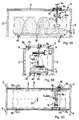
- Fig. 1A and 1B is an embodiment of a press ram 3 according to the invention for compressing and / or distributing compressible bulk material 1, such as garbage reproduced, which in the in Fig. 1A illustrated situation before compression forms a below the press ram 3 Schüttkegel.
- the ram 3 is formed with a raking device 300 arranged thereon, as described below with reference to Fig. 2A to 2D is explained in more detail.
- the ram 3 with the broach 300 is in the present embodiment in the by the arrow 4 (FIG. Fig. 1A and 1B ), for example, one or more, here two paired piston / cylinder unit (s) may be provided which operate hydraulically, pneumatically or hydropneumatically.
- the unit formed from press ram 3 and broaching device 300 is equipped with sensors S, such as ultrasound sensors or the like, so that depending on the surface contour, the bulk material 1 is only compressed ("compression mode"), only distributed (“distribution mode ”) or both compressed and distributed, for example, alternately and / or the distribution due to lateral displacement of the clearing device 300 takes place with a certain pressure on the bulk material 1.
- a load cycle of the compression stroke can be, for example, about 10 s to 30 s, depending on the bulk material 1 to be compacted and depending on the actuating device used for the press ram 3 and / or the reaming device 300.
- pneumatic cylinders for actuating the press ram 3 shorter compression strokes up to a few seconds, for example between about 1 s and about 10 s are possible, if desired.
- the ram 3 is arranged on a support structure 5.
- the support structure 5 has a plurality of supports 6, in this example, four the corners of a rectangle forming pillars 6, of which, for example, each two bear a guide rail 7.
- a carriage 8 Along the parallel guide rails 7 is a carriage 8, on which the ram 3 with the Clearing device 300 in the vertical direction 4 is arranged displaced back and forth, in the longitudinal direction of the rails 7 (arrow 10 of Fig. 1A ) guided linearly displaceable.
- the carriage 8 is guided linearly displaceably in the direction of the arrow 11 along the guide rails 7 and between these extending guide rails 9 in the transverse direction of the rails 7 (cf. Fig. 3C , there arrow 11).
- the guides formed by the guide rails 7 and 9 of the guide rails thus clamp with respect to the vertical displacement of the press ram 3 with the reamer 300 (arrow 4) vertical, horizontal x, y plane, wherein the ram 3 with the reamer 300 in two Arranged perpendicular to each other directions x and y (arrows 10 and 11) of this plane relative to the bulk material 1 to compress the latter and / or distribute.
- each motor 14 15 (see also Figs. 3B and 3C ), eg electric motors, may be provided.
- the guides formed by the guide rails 7 and 9 in the horizontal x, y plane need not necessarily extend perpendicular to each other nor have to have a linear course. However, you should ensure that the ram 3 with the reamer 300 is substantially horizontally displaceable so that it can be moved to any area of the can penetrate between the supports 6 bulk material 1 poured.
- FIG. 2A to 2C It can be seen which various detailed views of the unit formed from press ram 3 and 300 clearing device according to Fig. 1A and 1B show the punch 3 is formed in the present embodiment in the form of a substantially kastenfömigen press ram on the lower side of the broaching device 300 is arranged in relation to the ram 3 itself in linearly displaceable, in parallel to the surface extension of the ram 3, horizontal plane.
- the clearing device 300 has a plate 301 which can be displaced translationally back and forth along a guide 302 located on the press ram 3, the plate being in contact with the bulk material 1 (FIG. Fig.
- plate 301 of the reamer 300 for example, the ram 3 in the width completely spans, while the length of the plate 301 is less than the length of the ram 3 and the plate 301 substantially between the positions in which it does not protrude beyond the ram 3 , Is displaced back and forth to ensure high pressure stability due to constant support by the ram 3.
- parallel guide rails 303 which in each case receive two skids 304 between them, in each case via a respective approximately perpendicular to the plate 301 extending support 305 with the plate 301 , preferably in the region of their ends, are connected.
- a plurality of carriers 310 are arranged on the lower, the ram 3 facing away from the plate 301 of the broaching device 300, which extend in the present case, for example, approximately perpendicular to the direction of movement of the broach and are designed substantially in the form of strips, which after projecting down from the plate 301.
- the drivers 310 can be fixed to the plate 301 by means of screws 311, for example.
- the free edges of the dogs 310 are preferably equipped with a - eg approximately trapezoidal - profile 312 to provide good engagement in the to be compacted / distributing bulk material 1.
- the ram 3 is in this way both for compression or compression of the bulk material 1 by performing substantially vertical compression strokes, as well as for distributing bulk cones of the bulk material 1 in a position by the plate 301 of the reamer 300 along the guides 302 shifted is and the carrier 310 in this case the bulk material 1 laterally from the ram 3 continue to promote.
- the sensors S for detecting the surface contour of the bulk material 1 are in this case arranged in the case of the present embodiment, for example, on the narrow sides of the press ram 3 and clearing unit 300 formed unit.
- the container 2 may be, for example, a common standard container having a substantially rectangular free cross section and a length of about 12 meters and a width of about 2.40 meters.
- the cross-section of the ram 3 with the reamer 300 is substantially smaller than the free cross-section of the container 2 and in the present embodiment, for example between about half and about a square meter, So about 3% to 7% of the free cross-section of the container. 1
- FIGS. 4A to 4C illustrated embodiment of an apparatus for compressing and / or distributing a compressible bed 1 differs from the device according to Figs. 3A to 3C primarily in that the relative displacement between the container 2 and the - in the present case again in the vertical direction 4 back and forth displaceable - Preßstempel 3 with the reamer 300 thereby happens by the container 2 in a horizontal x, y plane displaced and the ram 3 is arranged stationary on the support structure 5.
- the container 2 can be erected on a first - upper - platform 20, which is equipped with drive rollers 21, which are guided along a second - lower - platform 22 provided guide 23.
- the guide 23 (see in particular Fig.
- the second - lower - platform 22 is in turn equipped with drive rollers 25, which in an example provided on the ground below the support structure 5 guide 26 (see Fig. 4C ), wherein the guide 26 of the lower platform 22 in the present embodiment again - although not necessarily - perpendicular to the guide 23 of the upper platform 20, that is approximately in the longitudinal direction of the container 2, and extends as well as the latter extends substantially linearly , so that the lower platform 22 in the longitudinal direction (arrow 27 of Fig. 4A ) of the container 2 is displaceable.
- the guides 23, 26 of the platforms 20, 22 thus tension a horizontal x, y plane along which the container 2 can be moved relative to the - here stationary - ram 3 with the reamer 300, so that the latter to a can be moved to any area of the container 2 to compress the bulk material 1 located there and / or distributed from this cone evenly distributed in the container 2.
- Figs. 5A to 5C it is of course also possible that the displaceability of the container 2 relative to the ram 3 with the broaching device 300 is effected by both the container 2 and the Preßstempel 3 - for example, substantially perpendicular to each other - are displaced.
- the ram 3 with the reamer 300 similar to the embodiment according to Figs. 3A to 3C is arranged on a carriage 8a, which along two in the longitudinal direction of the container 2 extending, supported by the supports 6 guide rails 7 by means of a motor 15 driven drive rollers 13 is movable (arrow 10).
- the ram 3 with the broaching device 300 is in the present case, however, firmly fixed vertically on the extending between the guide rails 7 slide 8a back and forth (arrow 4), while the container 2 is placed on a equipped with drive rollers 21 platform 20.
- the drive rollers 21 of the platform 20 are along perpendicular to the guide rails 7 of the carriage 8a of the press ram 3 extending guides 23 movable (arrow 24), the latter substantially the guides 23 according to FIGS. 4A to 4C can be designed accordingly.
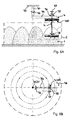
- FIGS. 6A to 6B show an embodiment of an inventive device for compressing and / or distributing compressible bulk material 1, wherein the relative displacement between the ram 3 with the broaching device 300 and the container 2 in an approximately horizontal x, y plane thereby takes place by a rotational movement is combined with a translational, radial to the axis of rotation of the rotational displacement.
- the container 2- here essentially circular-cylindrical-is arranged stationarily on the floor.
- a vertical shaft 30 formed by a stationary shaft 31 rotatable (arrow 32), the axis 31 expedient with the center of the container 2 is aligned.
- the shaft 30 may in the region of its upper, the container 2 opposite end, for example, at an in FIGS. 6A and 6B not shown in detail support structure 33, which engages over the container 2.
- the shaft 30 is rotatably supported about the axis 31 via a rotary drive also not shown on the support structure 33.
- a guide 34 In the region of its lower end extends from the shaft 30, a guide 34 radially outwardly, wherein a drive provided with rollers 36 slide 35, to which the ram 3 with the clearing device 300 is set vertically displaceable back and forth (arrow 4 of Fig. 6A ), along this guide 34 radially - in the present case linear - is movable (arrow 37).
- the guide 34 projects preferably approximately from the shaft 30 to the edge of the container 2 radially outward in order to move the ram 3 approximately within the entire free cross section of the container 2 relative to this.
- guide 34 biases a horizontal x, y plane along which the ram 3 with the reamer 300 can be moved relative to the container 2, so that the former to any area of the container. 2 can be shifted to compress the bulk material 1 located there and / or distribute.
- the ram 3 with the broaching device according to the arrow 38 is rotatable about a vertical axis, so that the broaching device 300 depending on their rotational position, the bulk material substantially in the circumferential direction of the container 2 or radially inward / outward can distribute.
- This axis may for example be formed by a piston / cylinder unit, by means of which the ram 3 with the clearing device can perform the compression strokes.
- Figs. 7A and 7B reproduced embodiment operates on the same principle as the embodiment according to FIGS. 6A and 6 , differs from this but in particular in that the vertically displaceable back and forth ram 3 with the reamer 300 (arrow 4 of Fig. 7A ) is mounted stationarily on the support structure 33, while the container 2 is displaceable relative thereto.
- the container 2 is placed on a first - upper - platform 40, which is rotatable about a central shaft 41 about an axis 42.
- the axle 42 is also translational - linear in the present case - moved by the arranged on the underside of the upper platform 40 shaft 41 is disposed at its lower end facing away from the upper platform 40 on a second - lower - platform 43 which is provided with drive rollers 44 which are guided along guides 45 (FIG. Fig. 7B ) is guided.
- the rotation of the platforms 40, 43 happens, for example, by the shaft 41 rotatably connected to one of the platforms 40, 43 and by means of a rotary drive (not shown) with respect to the other platform 43, 40 in the direction of arrow 46 can be rotated.
- Figs. 8A and 8B illustrated embodiment of an apparatus for compressing and / or distributing compressible bulk material 1, the displaceability of the container 2 relative to the ram 3 with the broaching device 300 - as far as similar to the embodiment according to Figs. 5A to 5C - Guaranteed by both the container 2 and the ram 3 with the reamer 300 are displaced.
- a rotational movement of the container 2 is combined with a translational movement of the press ram 3 with the broaching device 300.
- the container 2 is on an example of the upper Platform 40 according to Figs.
- FIG. 7A and 7B corresponding platform 40a is set up, which is rotatable about a central shaft 41a about an axis 42a (arrow 46 of Fig. 8B ).
- the axis 42 a is stationary and mounted at its lower end via a rotary drive (not shown) on the ground and rotatably secured at its upper end to the center of the platform 40 a at the bottom, so that the platform 40 a with the container carried by them 2 is freely rotatable about the stationary axis 42a.
- the ram 3 with the broach 300 is - for example, in a corresponding manner as in the embodiment according to Figs.
- the case is - attached to a carriage 8a, which is translationally guided along parallel guide rails 7, which in turn are supported by the supports 6 of the support structure 4.
- the drive of the carriage 8a of the ram 3 is done via driven by a motor 15 drive rollers 13 along the guide rails 7 in the direction of the arrow 47 (see, in particular Fig. 8A ).
- the rotatable in particular freely about the axis 42a platform 40a thus tensioned in conjunction with the guide rails 7 of the carriage 8a of the ram 3 with the broaching device 300 a horizontal x, y plane along which the container 2 and the ram 3 are moved relative to each other can, so that any area of the container 2 can be moved to the ram 3 with the reamer 300 or below it to compress the bulk material 1 located there and / or distribute.
- the pressing ram 3 with the raking device 300 can in turn be rotatable about a substantially vertical axis (arrow 38 of FIG Fig. 8A ), to the desired clearing direction of - in the present case translationally displaced in the direction of arrow 307 back and forth - Clearing device 300 (see also Fig. 2 ) to change as desired.
- FIGs. 9A and 9B as in Figs. 10A and 10B Embodiments of inventive devices for compacting and / or distributing bulk material 1 are shown in which the ram 3 with the reaming device 300 is not only vertically displaceable back and forth, but is also pivotally mounted about a substantially horizontal axis.
- the in Figs. 9A and 9B embodiment shown substantially on the principle of the above with reference to Figs.
- 3A to 3C illustrated embodiment differs from this primarily in that the ram 300 with the broaching device 300 on the along the guide rails 7 in the longitudinal direction of - for example, stationary parked on the ground - container 2 about an axis 50 (see arrow 51) is pivotable, wherein the axis 50 extends in the longitudinal direction of the container 2.
- a further, perpendicular to the guide rails 7 extending guide 9 see. Figs.
- Figs. 10A and 10B illustrated embodiment is based essentially on the principle of the above with reference to Figs. 5A to 5C explained embodiment in which the relative displacement of the press ram 3 with the reamer 300 with respect to the container 2 on the one hand by a displacement of the platform 20 with the container 2 along the guides 23 in the direction of arrow 24 and on the other hand by a displacement of the carriage 8a with the ram takes place along the guide rails 7 in the direction of the arrow 10.
- shown embodiment is compared to the embodiment according to Figs.
- a further development of the invention is when the ram 300 with the reaming device 300 is pivotally mounted there on the carriage 8a about a horizontal axis 60 in the direction of the arrow 61, resulting in a faster and / or more accurate positioning of the ram 3 at or above a desired container area easier to compact the bulk material 1 located there and / or distribute.
- the pivot axis 60 of the ram 3 with the broaching device 300 in contrast to the in Figs. 9A and 9B shown embodiment, for example, in the transverse direction of the carried by the platform 20 container 2.
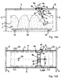
- FIGs. 11A to 11D is another one of them Figs. 3A to 3C corresponding embodiment of a device according to the invention for compressing and / or distributing bulk material 1 reproduced, which is further equipped with a feed device 70, via which the bulk material 1 in the container 2 can be transferred.
- the feeding device 70 has a conveyor belt 71 extending, for example, in the longitudinal direction of the container 2, which conveyor belt is fixed to a further carriage 72, which - like the carriage 8 with the ram 3 equipped with the raking device 300 the guide rails 7 in the longitudinal direction of the container 2 is displaced (see, in particular Fig. 11A , Arrow 75).
- the carriage 72 carrying the conveyor belt 71 is provided with drive rollers 73, which are driven by a motor 74, such as an electric motor.
- a motor 74 such as an electric motor
- the conveyor belt 71 transversely to the guide rails 7 is displaced (not shown), which can also be done for example by means of electric motors.
- a hopper 76 - for example, stationary on the support structure 5 - arranged to give the bulk material 1 the conveyor belt 72 can (arrow 77).
- the hopper 76 is arranged at such a position that it opens in any relative position of the displaceable along the guide rails 7 conveyor belt 72 relative to the container 2 and / or relative to the carriage 8 with the ram 3 in the conveyor belt 72.
- a discharge point 80 of the feeder 70 is set, via which the bulk material 1 is transferred into the container 2 and falls into it.
- the conveyor 70 is further a weighing device 90 in the form of a belt weigher (see, in particular Fig.
- the weighing device 90 is preferably designed for continuously weighing the mass flow of the bulk material 1 passing through it, so that an overloading of the container 2, as in particular in the case of a container permanently or detachably connected to a truck (in FIG Figs. 11A to 11D not shown) must be reliably excluded, is avoided.
- sensors S 1 , S 2 can also be provided which are used to scan the relative positions of the ram 3 and / or the feed device 70 are formed with respect to the container 2 or the bulk material 1 located therein in order to be able to displace the press ram 3 with the reaming device 300 and / or the feed device 70 in dependence on it to a respectively suitable position relative to the container 2.
- sensors S 3 may be provided, which are arranged such that they can detect the relative position of the conveyor 70 with respect to the container 2.
- Fig. 11D shows one of the Fig. 11A corresponding view of the same embodiment of an inventive device for compressing and / or distributing bulk material 1, wherein a schematic block diagram of a programmable controller 100 of the device is indicated.
- the controller 100 includes a microprocessor 101, in which a plurality of programmable parameters, such as the container volume V, the maximum compression force F max of the ram 3 with the reamer 300, the maximum filling amount m max of the container 2, the speed v R of the relative displacement of ram 3 and / or feeder 70 with respect to the container 2, the speed v R 'of the relative displacement of reamer 300 with respect to the ram 3 and optionally other parameters, such as the height H v and / or the time T v of a compression stroke of the ram 3, etc., can be entered.
- a plurality of programmable parameters such as the container volume V, the maximum compression force F max of the ram 3 with the reamer 300, the maximum filling amount m max of the container
- a plurality of sensor-detectable parameters such as measured by the weighing device 90 material flow M 'of the bulk material 1, the determined by the sensors S 1 , S 2 , S 3 position of the press ram 3 with the broaching device and the feeder 70 and the fill level H S of the bulk material 1 or its surface contour, etc. determined at the respective relative position of the ram 3 and the feed device 70 and container 2, can be transmitted to the microprocessor 101.
- the microprocessor 101 calculates from the parameters mentioned a suitable operation, which, for example, the control of the displacement s Z of the feeder 70 along the guide rails 7, the displacement s P of the press ram 3 with the broaching device 300 along the guides 7 and 9, the compression stroke s V and / or the compression force F V of the press ram 3, the displacement of the reaming device 300 with respect to the ram 3, etc. includes.
- a suitable operation which, for example, the control of the displacement s Z of the feeder 70 along the guide rails 7, the displacement s P of the press ram 3 with the broaching device 300 along the guides 7 and 9, the compression stroke s V and / or the compression force F V of the press ram 3, the displacement of the reaming device 300 with respect to the ram 3, etc.
- a suitable operation which, for example, the control of the displacement s Z of the feeder 70 along the guide rails 7, the displacement s P of the press ram 3 with the broaching device 300 along the guides 7 and 9, the compression stroke s V
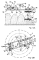
- FIGS. 6A and 6B corresponding embodiment of a device according to the invention for compressing and / or distributing bulk material 1, which is in turn equipped with a feed device 70, via which the bulk material 1 in the container 2 can be transferred.
- a feed device 70 extends to the Shaft 30 arranged and rotatable about the stationary axis 31 guide 34 substantially over the entire diameter of the container 2 and is fixed to the guide 34 in addition to the carriage 35, to which the ram 3 with the clearing device 300 is vertically displaceable back and forth ( Arrow 4 of Fig. 12A ), a feeder 70 guided.
- the feed device 70 in turn, essentially corresponds to FIG Figs.
- the hopper 76 is disposed at a position such that it in any relative position of the displaceable along the guide conveyor belt 72 72 relative to the container 2 and / or relative to the carriage 35 with the ram 3 and the reamer 300 in the Conveyor 72 opens.
- a discharge point 80 of the conveyor 70 is set, via which the bulk material 1 is transferred into the container 2 and falls into this.
- the conveyor 70 and / or the container 2 can also have an in Figs. 12A and 12B not reproduced weighing device 90 may be assigned, which, for example, similar to the weighing device 90 according to Figs. 11A to 11D can be designed.
- the reamer 300 may be rotatable about an approximately vertical direction (arrow 38 of FIG Fig. 12A ), in order to be able to move clearing means 300 (see also FIG Fig. 2 ) to be able to adjust any conveying direction of the ram 3 continued.
- Figs. 13A and 13B show one of the device according to Figs. 12A and 12B practically functionally identical device for compacting and / or distributing bulk material 1 (without feed hopper 76), wherein in Fig. 13A the reamer 300 together with the ram 3 in relation to the Fig. 12A has been pivoted by 90 ° in the direction of arrow 38 about the vertical axis of the ram 3 bearing the ram 300 piston / cylinder unit.
- Corresponding sensors S 1 , S 2 , S 3 in turn provide, in conjunction with a control, not shown, for the detection of the (relative) positions of ram 3 with clearing device 300, in the container 2 existing bulk cones of bulk material 1 and feeder 70th
- the container (s) 2 can also be arranged on a vehicle, such as a truck, with the container (s) 2 of the truck directly filled with bulk material 1 and then compacted and / or evenly packed in the container (s) ) 2, or a container 2 is filled while the bulk material 1 of the other - already filled - container 2 is compressed and / or distributed.
- sensors S 1 , S 2 , S 3 can serve to detect the position of the containers and the bulk material of the bulk material 1 already present therein and / or detect an imminent collision of the container 2 with parts of the truck at an early stage and - if they are, for example, operatively connected to a warning device - prevent.
- Figs. 15A to 15C which is also shown there during filling and compression / distribution of the filled bulk material 1 in a container 2 arranged on a truck, instead of a stationary arranged on the support structure hopper 76 of the feeder 70, as he eg Figs. 11A to 11D is provided, a laterally opening into the conveyor belt 71 of the feeder 70 conveyor belt 130 is provided which can be equipped with bulk material via a feed hopper 76a. Otherwise corresponds to in Figs. 15A to 15C reproduced device as far as possible according to Figs. 11A to 11D ,
- FIG. 16A to 16C a likewise of the device according to Figs. 11A to 11D largely similar device in an operating state, as in Figs. 15A to 15C is shown.
- the device according to Figs. 16A to 16C differs from the according to Figs. 11A to 11D mainly in that the feed device 70 instead of the hopper 76 ( Figs. 11A to 11D ) is equipped with a fluidic, eg pneumatic gripper unit 140, via which the conveyor belt 71 of the feed device 70 can be acted upon with bulk material 1, before the latter passes via the conveyor belt 71 into the container 2.
- a fluidic, eg pneumatic gripper unit 140 via which the conveyor belt 71 of the feed device 70 can be acted upon with bulk material 1, before the latter passes via the conveyor belt 71 into the container 2.
Landscapes
- Engineering & Computer Science (AREA)
- Mechanical Engineering (AREA)
- Refuse Collection And Transfer (AREA)
- Filling Or Emptying Of Bunkers, Hoppers, And Tanks (AREA)
Applications Claiming Priority (1)
| Application Number | Priority Date | Filing Date | Title |
|---|---|---|---|
| DE202007010997U DE202007010997U1 (de) | 2007-08-07 | 2007-08-07 | Vorrichtung zum Verdichten von komprimierbarem Schüttgut und Preßorgan einer solchen Vorrichtung |
Publications (3)
| Publication Number | Publication Date |
|---|---|
| EP2027992A2 true EP2027992A2 (fr) | 2009-02-25 |
| EP2027992A3 EP2027992A3 (fr) | 2011-04-20 |
| EP2027992B1 EP2027992B1 (fr) | 2014-10-08 |
Family
ID=39744544
Family Applications (1)
| Application Number | Title | Priority Date | Filing Date |
|---|---|---|---|
| EP08013649.2A Not-in-force EP2027992B1 (fr) | 2007-08-07 | 2008-07-30 | Procédé et dispositif destinés à la compression de produits en vrac |
Country Status (2)
| Country | Link |
|---|---|
| EP (1) | EP2027992B1 (fr) |
| DE (1) | DE202007010997U1 (fr) |
Cited By (3)
| Publication number | Priority date | Publication date | Assignee | Title |
|---|---|---|---|---|
| CN108639631A (zh) * | 2018-03-29 | 2018-10-12 | 南安市森电子科技有限公司 | 一种垃圾车的垃圾处理装置 |
| CN111115054A (zh) * | 2020-01-13 | 2020-05-08 | 小圾(上海)环保科技有限公司 | 一种干垃圾压缩装置 |
| CN114312547A (zh) * | 2021-12-09 | 2022-04-12 | 华能伊春热电有限公司 | 一种货车自动盖篷布装置 |
Families Citing this family (3)
| Publication number | Priority date | Publication date | Assignee | Title |
|---|---|---|---|---|
| DE202015008797U1 (de) * | 2015-12-23 | 2017-03-24 | Faun Umwelttechnik Gmbh & Co. Kg | Füllstandsabhängige Ladewerksteuerung eines Abfallsammelfahrzeugs |
| CN108438679A (zh) * | 2018-03-29 | 2018-08-24 | 南安市森电子科技有限公司 | 一种垃圾车用的垃圾处理装置 |
| WO2021075606A1 (fr) * | 2019-10-18 | 2021-04-22 | (주)에이씨아이케미칼아시아 | Dispositif de collecte de charge |
Citations (11)
| Publication number | Priority date | Publication date | Assignee | Title |
|---|---|---|---|---|
| DE8228963U1 (de) | 1982-10-15 | 1984-03-08 | Bergmann, Heinz, 4474 Lathen | Vorrichtung zum verdichten von aus verpackungsmaterial und leicht pressbaren abfaellen bestehendem muell |
| DE3406879A1 (de) | 1984-02-25 | 1985-08-29 | Heinz 4474 Lathen Bergmann | Vorrichtung zum verdichten von aus verpackungsmaterial und leicht pressbaren abfaellen bestehendem muell |
| DE3637769A1 (de) | 1986-11-06 | 1988-05-19 | Theodor Lentjes | Verwendung eines eigensteifen behaelters zur aufnahme komprimierter gueter |
| DE3903642A1 (de) | 1989-02-08 | 1990-08-09 | Heinz Bergmann | Vorrichtung zum verdichten von aus verpackungsmaterial bestehendem muell |
| DE3926866A1 (de) | 1989-08-16 | 1991-02-21 | Muepa Muell Papierverwertung | Vorrichtung zum sammeln von insbesondere altpapier und kartonagen |
| DE4013107A1 (de) | 1990-04-25 | 1991-10-31 | Andreas Benz Apparatebau Gmbh | Pressvorrichtung fuer muell |
| DE4237143A1 (en) | 1991-12-04 | 1993-06-09 | Ulrich 6927 Bad Rappenau De Zehner | Compactor for refuse in refuse skip - has swinging panel with flap which is retracted on up-stroke of panel |
| DE4301627A1 (de) | 1993-01-22 | 1994-07-28 | Ruhrkohle Ag | Schüttgutplaniervorrichtung |
| DE9314726U1 (de) | 1993-09-29 | 1995-02-02 | Hommel, Rolf, 81241 München | Vorrichtung in Portalbauweise zum Verdichten von Feststoffen in Behältern |
| EP0798044A1 (fr) | 1996-03-26 | 1997-10-01 | ALFA S.r.l. | Appareil de broyage avec sélection de matériau et compacteur rotatif |
| EP1762374A2 (fr) | 2005-09-10 | 2007-03-14 | Andreas Hagemann | Procédé et dispositif pour compacter des matériaux en vrac compressibles |
Family Cites Families (10)
| Publication number | Priority date | Publication date | Assignee | Title |
|---|---|---|---|---|
| GB290851A (en) * | 1927-06-24 | 1928-05-24 | Thomas Charles Oughton | An improved refuse conveyance |
| US4411578A (en) * | 1981-09-25 | 1983-10-25 | Aggregates Equipment, Inc. | Shuttle spreading conveyor |
| DE3524780C2 (de) * | 1985-07-11 | 1994-05-11 | Westfalia Becorit Ind Tech | Räumeinrichtung für Bunker u.dgl. |
| US4716825A (en) * | 1987-01-30 | 1988-01-05 | Chester Lemmond | Vehicle mounted compaction implement |
| US5167185A (en) * | 1991-01-04 | 1992-12-01 | The Kbh Corporation | Cotton module builder including a hydraulically motorized bridge assembly |
| GB2261626B (en) * | 1991-11-21 | 1995-03-22 | Kenbay Ltd | A waste compactor |
| GB2303115A (en) * | 1995-07-12 | 1997-02-12 | Turner Grain & Feed Milling Li | Loading Bulk Material |
| FR2802462B1 (fr) * | 1999-12-18 | 2002-03-01 | Valdec | Procede de compactage de dechets et machine pour sa mise en oeuvre |
| FR2840249B1 (fr) * | 2002-05-30 | 2004-12-24 | J S B Const | Dispositif compacteur de dechets contenus dans des conteneurs |
| NO317713B1 (no) * | 2002-10-29 | 2004-12-06 | Repant As | Anordning ved returautomat |
-
2007
- 2007-08-07 DE DE202007010997U patent/DE202007010997U1/de not_active Expired - Lifetime
-
2008
- 2008-07-30 EP EP08013649.2A patent/EP2027992B1/fr not_active Not-in-force
Patent Citations (11)
| Publication number | Priority date | Publication date | Assignee | Title |
|---|---|---|---|---|
| DE8228963U1 (de) | 1982-10-15 | 1984-03-08 | Bergmann, Heinz, 4474 Lathen | Vorrichtung zum verdichten von aus verpackungsmaterial und leicht pressbaren abfaellen bestehendem muell |
| DE3406879A1 (de) | 1984-02-25 | 1985-08-29 | Heinz 4474 Lathen Bergmann | Vorrichtung zum verdichten von aus verpackungsmaterial und leicht pressbaren abfaellen bestehendem muell |
| DE3637769A1 (de) | 1986-11-06 | 1988-05-19 | Theodor Lentjes | Verwendung eines eigensteifen behaelters zur aufnahme komprimierter gueter |
| DE3903642A1 (de) | 1989-02-08 | 1990-08-09 | Heinz Bergmann | Vorrichtung zum verdichten von aus verpackungsmaterial bestehendem muell |
| DE3926866A1 (de) | 1989-08-16 | 1991-02-21 | Muepa Muell Papierverwertung | Vorrichtung zum sammeln von insbesondere altpapier und kartonagen |
| DE4013107A1 (de) | 1990-04-25 | 1991-10-31 | Andreas Benz Apparatebau Gmbh | Pressvorrichtung fuer muell |
| DE4237143A1 (en) | 1991-12-04 | 1993-06-09 | Ulrich 6927 Bad Rappenau De Zehner | Compactor for refuse in refuse skip - has swinging panel with flap which is retracted on up-stroke of panel |
| DE4301627A1 (de) | 1993-01-22 | 1994-07-28 | Ruhrkohle Ag | Schüttgutplaniervorrichtung |
| DE9314726U1 (de) | 1993-09-29 | 1995-02-02 | Hommel, Rolf, 81241 München | Vorrichtung in Portalbauweise zum Verdichten von Feststoffen in Behältern |
| EP0798044A1 (fr) | 1996-03-26 | 1997-10-01 | ALFA S.r.l. | Appareil de broyage avec sélection de matériau et compacteur rotatif |
| EP1762374A2 (fr) | 2005-09-10 | 2007-03-14 | Andreas Hagemann | Procédé et dispositif pour compacter des matériaux en vrac compressibles |
Cited By (3)
| Publication number | Priority date | Publication date | Assignee | Title |
|---|---|---|---|---|
| CN108639631A (zh) * | 2018-03-29 | 2018-10-12 | 南安市森电子科技有限公司 | 一种垃圾车的垃圾处理装置 |
| CN111115054A (zh) * | 2020-01-13 | 2020-05-08 | 小圾(上海)环保科技有限公司 | 一种干垃圾压缩装置 |
| CN114312547A (zh) * | 2021-12-09 | 2022-04-12 | 华能伊春热电有限公司 | 一种货车自动盖篷布装置 |
Also Published As
| Publication number | Publication date |
|---|---|
| DE202007010997U1 (de) | 2008-09-11 |
| EP2027992B1 (fr) | 2014-10-08 |
| EP2027992A3 (fr) | 2011-04-20 |
Similar Documents
| Publication | Publication Date | Title |
|---|---|---|
| DE69314737T2 (de) | Lagerregal mit beweglichen Gestellen | |
| EP2027992B1 (fr) | Procédé et dispositif destinés à la compression de produits en vrac | |
| EP1149203B1 (fr) | Dispositif d'introduction de goujons dans des revetements de chaussee fraichement etendus | |
| DE3614328C2 (de) | Schüttung an einem Müllfahrzeug und Müllbehälter für diese Schüttung | |
| EP0364835A1 (fr) | Véhicule de ramassage d'ordures | |
| EP0556363B1 (fr) | Presse verticale et son procede d'utilisation | |
| DE102007013382A1 (de) | Verfahren zum Herstellen eines Pressballens und Vorrichtung zum Herstellen von Pressballen | |
| DE2634634A1 (de) | Stapel- und einfuellvorrichtung fuer bahnteile aus kompressiblem material | |
| EP1641686B1 (fr) | Installation de collecte differenciee et non differenciee de dechets menagers | |
| EP3915770B1 (fr) | Dispositif élévateur-culbuteur, presse à balles équipée d'un tel dispositif, ainsi que son procédé de fonctionnement | |
| DE10391685B4 (de) | Presse zum Bearbeiten von Material beliebiger Art | |
| EP2292417B1 (fr) | Presse à balles à canal | |
| DE2556168C2 (de) | Ballenpresse zum Pressen von Altmaterial | |
| EP3842223B1 (fr) | Presse à balles verticale ainsi que son procédé de fonctionnement | |
| EP1762374A2 (fr) | Procédé et dispositif pour compacter des matériaux en vrac compressibles | |
| AT509952B1 (de) | Verfahren und vorrichtung zum fördern und puffern von gepressten paketen | |
| DE202006008528U1 (de) | Vorrichtung zum Verdichten vom komprimierbarem Schüttgut | |
| EP1859925A1 (fr) | Dispositif destiné à comprimer des produits en vrac comprimables | |
| DE69600944T2 (de) | Vorrichtung zum getrennten Sammeln von Müll | |
| DE2908208A1 (de) | Muellfahrzeug mit hinter dem sammelbehaelter gelegenem einfuellraum und einem trogfoermigen vorverdichtungsraum | |
| EP3415305B1 (fr) | Unité de presse à déchets stationnaire à relier à un conteneur d'échange mobile | |
| EP0363621B1 (fr) | Presse pour compacter des éléments radioactifs de structure oblongue et procédé pour son utilisation | |
| DE3625336C2 (fr) | ||
| DE19730235C1 (de) | Einrichtung zum Fördern von Preßballen aus stationären Ballenpressen | |
| EP0562487B1 (fr) | Presse pour déchets avec un bâti et un réceptacle |
Legal Events
| Date | Code | Title | Description |
|---|---|---|---|
| PUAI | Public reference made under article 153(3) epc to a published international application that has entered the european phase |
Free format text: ORIGINAL CODE: 0009012 |
|
| AK | Designated contracting states |
Kind code of ref document: A2 Designated state(s): AT BE BG CH CY CZ DE DK EE ES FI FR GB GR HR HU IE IS IT LI LT LU LV MC MT NL NO PL PT RO SE SI SK TR |
|
| AX | Request for extension of the european patent |
Extension state: AL BA MK RS |
|
| PUAL | Search report despatched |
Free format text: ORIGINAL CODE: 0009013 |
|
| AK | Designated contracting states |
Kind code of ref document: A3 Designated state(s): AT BE BG CH CY CZ DE DK EE ES FI FR GB GR HR HU IE IS IT LI LT LU LV MC MT NL NO PL PT RO SE SI SK TR |
|
| AX | Request for extension of the european patent |
Extension state: AL BA MK RS |
|
| 17P | Request for examination filed |
Effective date: 20110823 |
|
| AKX | Designation fees paid |
Designated state(s): AT BE BG CH CY CZ DE DK EE ES FI FR GB GR HR HU IE IS IT LI LT LU LV MC MT NL NO PL PT RO SE SI SK TR |
|
| 17Q | First examination report despatched |
Effective date: 20131004 |
|
| GRAP | Despatch of communication of intention to grant a patent |
Free format text: ORIGINAL CODE: EPIDOSNIGR1 |
|
| INTG | Intention to grant announced |
Effective date: 20140217 |
|
| GRAP | Despatch of communication of intention to grant a patent |
Free format text: ORIGINAL CODE: EPIDOSNIGR1 |
|
| GRAP | Despatch of communication of intention to grant a patent |
Free format text: ORIGINAL CODE: EPIDOSNIGR1 |
|
| INTG | Intention to grant announced |
Effective date: 20140520 |
|
| INTG | Intention to grant announced |
Effective date: 20140612 |
|
| GRAS | Grant fee paid |
Free format text: ORIGINAL CODE: EPIDOSNIGR3 |
|
| GRAA | (expected) grant |
Free format text: ORIGINAL CODE: 0009210 |
|
| AK | Designated contracting states |
Kind code of ref document: B1 Designated state(s): AT BE BG CH CY CZ DE DK EE ES FI FR GB GR HR HU IE IS IT LI LT LU LV MC MT NL NO PL PT RO SE SI SK TR |
|
| REG | Reference to a national code |
Ref country code: GB Ref legal event code: FG4D Free format text: NOT ENGLISH |
|
| REG | Reference to a national code |
Ref country code: AT Ref legal event code: REF Ref document number: 690357 Country of ref document: AT Kind code of ref document: T Effective date: 20141015 Ref country code: CH Ref legal event code: EP |
|
| REG | Reference to a national code |
Ref country code: IE Ref legal event code: FG4D Free format text: LANGUAGE OF EP DOCUMENT: GERMAN |
|
| REG | Reference to a national code |
Ref country code: DE Ref legal event code: R096 Ref document number: 502008012289 Country of ref document: DE Effective date: 20141113 |
|
| REG | Reference to a national code |
Ref country code: NL Ref legal event code: VDEP Effective date: 20141008 |
|
| REG | Reference to a national code |
Ref country code: LT Ref legal event code: MG4D |
|
| PG25 | Lapsed in a contracting state [announced via postgrant information from national office to epo] |
Ref country code: NL Free format text: LAPSE BECAUSE OF FAILURE TO SUBMIT A TRANSLATION OF THE DESCRIPTION OR TO PAY THE FEE WITHIN THE PRESCRIBED TIME-LIMIT Effective date: 20141008 |
|
| PG25 | Lapsed in a contracting state [announced via postgrant information from national office to epo] |
Ref country code: PT Free format text: LAPSE BECAUSE OF FAILURE TO SUBMIT A TRANSLATION OF THE DESCRIPTION OR TO PAY THE FEE WITHIN THE PRESCRIBED TIME-LIMIT Effective date: 20150209 Ref country code: ES Free format text: LAPSE BECAUSE OF FAILURE TO SUBMIT A TRANSLATION OF THE DESCRIPTION OR TO PAY THE FEE WITHIN THE PRESCRIBED TIME-LIMIT Effective date: 20141008 Ref country code: IS Free format text: LAPSE BECAUSE OF FAILURE TO SUBMIT A TRANSLATION OF THE DESCRIPTION OR TO PAY THE FEE WITHIN THE PRESCRIBED TIME-LIMIT Effective date: 20150208 Ref country code: NO Free format text: LAPSE BECAUSE OF FAILURE TO SUBMIT A TRANSLATION OF THE DESCRIPTION OR TO PAY THE FEE WITHIN THE PRESCRIBED TIME-LIMIT Effective date: 20150108 Ref country code: FI Free format text: LAPSE BECAUSE OF FAILURE TO SUBMIT A TRANSLATION OF THE DESCRIPTION OR TO PAY THE FEE WITHIN THE PRESCRIBED TIME-LIMIT Effective date: 20141008 Ref country code: LT Free format text: LAPSE BECAUSE OF FAILURE TO SUBMIT A TRANSLATION OF THE DESCRIPTION OR TO PAY THE FEE WITHIN THE PRESCRIBED TIME-LIMIT Effective date: 20141008 |
|
| PG25 | Lapsed in a contracting state [announced via postgrant information from national office to epo] |
Ref country code: LV Free format text: LAPSE BECAUSE OF FAILURE TO SUBMIT A TRANSLATION OF THE DESCRIPTION OR TO PAY THE FEE WITHIN THE PRESCRIBED TIME-LIMIT Effective date: 20141008 Ref country code: CY Free format text: LAPSE BECAUSE OF FAILURE TO SUBMIT A TRANSLATION OF THE DESCRIPTION OR TO PAY THE FEE WITHIN THE PRESCRIBED TIME-LIMIT Effective date: 20141008 Ref country code: SE Free format text: LAPSE BECAUSE OF FAILURE TO SUBMIT A TRANSLATION OF THE DESCRIPTION OR TO PAY THE FEE WITHIN THE PRESCRIBED TIME-LIMIT Effective date: 20141008 Ref country code: PL Free format text: LAPSE BECAUSE OF FAILURE TO SUBMIT A TRANSLATION OF THE DESCRIPTION OR TO PAY THE FEE WITHIN THE PRESCRIBED TIME-LIMIT Effective date: 20141008 Ref country code: GR Free format text: LAPSE BECAUSE OF FAILURE TO SUBMIT A TRANSLATION OF THE DESCRIPTION OR TO PAY THE FEE WITHIN THE PRESCRIBED TIME-LIMIT Effective date: 20150109 Ref country code: HR Free format text: LAPSE BECAUSE OF FAILURE TO SUBMIT A TRANSLATION OF THE DESCRIPTION OR TO PAY THE FEE WITHIN THE PRESCRIBED TIME-LIMIT Effective date: 20141008 |
|
| REG | Reference to a national code |
Ref country code: DE Ref legal event code: R097 Ref document number: 502008012289 Country of ref document: DE |
|
| PG25 | Lapsed in a contracting state [announced via postgrant information from national office to epo] |
Ref country code: RO Free format text: LAPSE BECAUSE OF FAILURE TO SUBMIT A TRANSLATION OF THE DESCRIPTION OR TO PAY THE FEE WITHIN THE PRESCRIBED TIME-LIMIT Effective date: 20141008 Ref country code: CZ Free format text: LAPSE BECAUSE OF FAILURE TO SUBMIT A TRANSLATION OF THE DESCRIPTION OR TO PAY THE FEE WITHIN THE PRESCRIBED TIME-LIMIT Effective date: 20141008 Ref country code: SK Free format text: LAPSE BECAUSE OF FAILURE TO SUBMIT A TRANSLATION OF THE DESCRIPTION OR TO PAY THE FEE WITHIN THE PRESCRIBED TIME-LIMIT Effective date: 20141008 Ref country code: EE Free format text: LAPSE BECAUSE OF FAILURE TO SUBMIT A TRANSLATION OF THE DESCRIPTION OR TO PAY THE FEE WITHIN THE PRESCRIBED TIME-LIMIT Effective date: 20141008 Ref country code: DK Free format text: LAPSE BECAUSE OF FAILURE TO SUBMIT A TRANSLATION OF THE DESCRIPTION OR TO PAY THE FEE WITHIN THE PRESCRIBED TIME-LIMIT Effective date: 20141008 |
|
| PLBE | No opposition filed within time limit |
Free format text: ORIGINAL CODE: 0009261 |
|
| STAA | Information on the status of an ep patent application or granted ep patent |
Free format text: STATUS: NO OPPOSITION FILED WITHIN TIME LIMIT |
|
| PG25 | Lapsed in a contracting state [announced via postgrant information from national office to epo] |
Ref country code: IT Free format text: LAPSE BECAUSE OF FAILURE TO SUBMIT A TRANSLATION OF THE DESCRIPTION OR TO PAY THE FEE WITHIN THE PRESCRIBED TIME-LIMIT Effective date: 20141008 |
|
| 26N | No opposition filed |
Effective date: 20150709 |
|
| PG25 | Lapsed in a contracting state [announced via postgrant information from national office to epo] |
Ref country code: MC Free format text: LAPSE BECAUSE OF FAILURE TO SUBMIT A TRANSLATION OF THE DESCRIPTION OR TO PAY THE FEE WITHIN THE PRESCRIBED TIME-LIMIT Effective date: 20141008 Ref country code: SI Free format text: LAPSE BECAUSE OF FAILURE TO SUBMIT A TRANSLATION OF THE DESCRIPTION OR TO PAY THE FEE WITHIN THE PRESCRIBED TIME-LIMIT Effective date: 20141008 |
|
| REG | Reference to a national code |
Ref country code: CH Ref legal event code: PL |
|
| GBPC | Gb: european patent ceased through non-payment of renewal fee |
Effective date: 20150730 |
|
| PG25 | Lapsed in a contracting state [announced via postgrant information from national office to epo] |
Ref country code: LU Free format text: LAPSE BECAUSE OF FAILURE TO SUBMIT A TRANSLATION OF THE DESCRIPTION OR TO PAY THE FEE WITHIN THE PRESCRIBED TIME-LIMIT Effective date: 20150730 |
|
| REG | Reference to a national code |
Ref country code: IE Ref legal event code: MM4A |
|
| PG25 | Lapsed in a contracting state [announced via postgrant information from national office to epo] |
Ref country code: CH Free format text: LAPSE BECAUSE OF NON-PAYMENT OF DUE FEES Effective date: 20150731 Ref country code: GB Free format text: LAPSE BECAUSE OF NON-PAYMENT OF DUE FEES Effective date: 20150730 Ref country code: LI Free format text: LAPSE BECAUSE OF NON-PAYMENT OF DUE FEES Effective date: 20150731 |
|
| REG | Reference to a national code |
Ref country code: FR Ref legal event code: PLFP Year of fee payment: 9 |
|
| PG25 | Lapsed in a contracting state [announced via postgrant information from national office to epo] |
Ref country code: IE Free format text: LAPSE BECAUSE OF NON-PAYMENT OF DUE FEES Effective date: 20150730 |
|
| PGFP | Annual fee paid to national office [announced via postgrant information from national office to epo] |
Ref country code: DE Payment date: 20160816 Year of fee payment: 9 |
|
| PGFP | Annual fee paid to national office [announced via postgrant information from national office to epo] |
Ref country code: FR Payment date: 20160722 Year of fee payment: 9 Ref country code: AT Payment date: 20160720 Year of fee payment: 9 |
|
| PG25 | Lapsed in a contracting state [announced via postgrant information from national office to epo] |
Ref country code: MT Free format text: LAPSE BECAUSE OF FAILURE TO SUBMIT A TRANSLATION OF THE DESCRIPTION OR TO PAY THE FEE WITHIN THE PRESCRIBED TIME-LIMIT Effective date: 20141008 |
|
| PG25 | Lapsed in a contracting state [announced via postgrant information from national office to epo] |
Ref country code: BG Free format text: LAPSE BECAUSE OF FAILURE TO SUBMIT A TRANSLATION OF THE DESCRIPTION OR TO PAY THE FEE WITHIN THE PRESCRIBED TIME-LIMIT Effective date: 20141008 Ref country code: HU Free format text: LAPSE BECAUSE OF FAILURE TO SUBMIT A TRANSLATION OF THE DESCRIPTION OR TO PAY THE FEE WITHIN THE PRESCRIBED TIME-LIMIT; INVALID AB INITIO Effective date: 20080730 |
|
| PG25 | Lapsed in a contracting state [announced via postgrant information from national office to epo] |
Ref country code: BE Free format text: LAPSE BECAUSE OF NON-PAYMENT OF DUE FEES Effective date: 20150731 |
|
| PG25 | Lapsed in a contracting state [announced via postgrant information from national office to epo] |
Ref country code: TR Free format text: LAPSE BECAUSE OF FAILURE TO SUBMIT A TRANSLATION OF THE DESCRIPTION OR TO PAY THE FEE WITHIN THE PRESCRIBED TIME-LIMIT Effective date: 20141008 |
|
| REG | Reference to a national code |
Ref country code: DE Ref legal event code: R119 Ref document number: 502008012289 Country of ref document: DE |
|
| REG | Reference to a national code |
Ref country code: AT Ref legal event code: MM01 Ref document number: 690357 Country of ref document: AT Kind code of ref document: T Effective date: 20170730 |
|
| REG | Reference to a national code |
Ref country code: FR Ref legal event code: ST Effective date: 20180330 |
|
| PG25 | Lapsed in a contracting state [announced via postgrant information from national office to epo] |
Ref country code: DE Free format text: LAPSE BECAUSE OF NON-PAYMENT OF DUE FEES Effective date: 20180201 |
|
| PG25 | Lapsed in a contracting state [announced via postgrant information from national office to epo] |
Ref country code: FR Free format text: LAPSE BECAUSE OF NON-PAYMENT OF DUE FEES Effective date: 20170731 Ref country code: AT Free format text: LAPSE BECAUSE OF NON-PAYMENT OF DUE FEES Effective date: 20170730 |