EP2028079B1 - Elément de blindage et agencement de blindage - Google Patents
Elément de blindage et agencement de blindage Download PDFInfo
- Publication number
- EP2028079B1 EP2028079B1 EP07016410A EP07016410A EP2028079B1 EP 2028079 B1 EP2028079 B1 EP 2028079B1 EP 07016410 A EP07016410 A EP 07016410A EP 07016410 A EP07016410 A EP 07016410A EP 2028079 B1 EP2028079 B1 EP 2028079B1
- Authority
- EP
- European Patent Office
- Prior art keywords
- longitudinal axis
- screening element
- inner ring
- screening
- approximately
- Prior art date
- Legal status (The legal status is an assumption and is not a legal conclusion. Google has not performed a legal analysis and makes no representation as to the accuracy of the status listed.)
- Not-in-force
Links
Images

Classifications
-
- B—PERFORMING OPERATIONS; TRANSPORTING
- B62—LAND VEHICLES FOR TRAVELLING OTHERWISE THAN ON RAILS
- B62D—MOTOR VEHICLES; TRAILERS
- B62D1/00—Steering controls, i.e. means for initiating a change of direction of the vehicle
- B62D1/02—Steering controls, i.e. means for initiating a change of direction of the vehicle vehicle-mounted
- B62D1/16—Steering columns
-
- B—PERFORMING OPERATIONS; TRANSPORTING
- B60—VEHICLES IN GENERAL
- B60R—VEHICLES, VEHICLE FITTINGS, OR VEHICLE PARTS, NOT OTHERWISE PROVIDED FOR
- B60R13/00—Elements for body-finishing, identifying, or decorating; Arrangements or adaptations for advertising purposes
- B60R13/08—Insulating elements, e.g. for sound insulation
- B60R13/0846—Insulating elements, e.g. for sound insulation for duct, cable or rod passages, e.g. between engine and passenger compartments
- B60R13/0853—Insulating elements, e.g. for sound insulation for duct, cable or rod passages, e.g. between engine and passenger compartments specially adapted for movable parts, e.g. gears levers, pedals
Definitions
- the present invention relates to a shielding element according to claim 1 and a shielding arrangement according to claim 14.
- the DE 1 580 321 A1 is a device for carrying out the steering column of a motor vehicle and a plurality of adjacent the steering column parallel to this lines, sheaths for linkage parts and the like through the vehicle floor known, the steering column and the adjacent parts are passed without clearance through holes in a rubber plate, with its edge is located between two plates fixed together on the vehicle floor.
- the steering column and the adjacently arranged parts are vibration-isolated against the vehicle floor and also prevents draft, moisture or dirt at the openings for the steering column and for the adjacent parts can get into the interior of the cab ,
- the said sheets form holding parts, so that the pertinent holding plates and the rubber disc for installation with the steering column and the adjacent parts form a unit.
- a shielding element in which a funnel-shaped rubber boot is formed in the manner of a bellows between a bell-shaped Metallabdeckhaube with a receptacle for a steering linkage and an oppositely disposed trough-like receiving part, in the extension obliquely inclined flange parts are in abutment with an associated protruding Ring flange part of the extent elastically yielding bellows cover.
- a sound shield is achieved so far.
- a generic funnel-shaped shielding element for shielding against dirt, liquids, heat or cold at the implementation of a steering column from the passenger compartment into the engine compartment of a motor vehicle is off DE 10 2006 002 992 known.
- This shielding element is made of aluminum and forms an unfused truncated cone surface.
- the shielding element according to the invention has a tubular metal shaped part which defines a longitudinal axis.
- a rubber-elastic inner ring is inserted in a first end portion of the metal mold part.
- a rubber-elastic outer ring is placed on a second end portion of the metal mold part.
- the outer ring has an outwardly projecting flange portion at its end facing away from the metal mold part.
- the shielding element according to the invention encompasses a steering column which passes through a body panel of a motor vehicle.
- the inner ring of the shielding element bears against a bearing part mounted on the steering column.
- a flange portion of the outer ring engages in an associated receiving space on the body panel.
- a shielding element according to the invention requires a smaller metal shaped part, so that material costs can be saved.
- the shield receives the necessary flexibility to damp vibration occurring in the motor vehicle.
- the load of the metal molding is reduced and increases the life of the shielding.
- the rubber-elastic elements can be easily attached to the metal molding and allow easier installation of the shielding in the vehicle.
- the shield arrangement allows a more complete shield against dirt and heat or cold. This better protects the area behind the shield, resulting in less wear and maintenance.
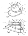
- the Figures 1 and 2 1 shows an embodiment of a shielding element 10 according to the invention.
- the shielding element 10 has a tubular metal mold part 14 defining a longitudinal axis 12.
- a first end 19 associated first end portion 20 of the metal mold part 14, a rubber-elastic inner ring 16 is inserted under frictional engagement.
- the inner ring 16 has an annular body part 22 with an approximately rectangular cross section and an annular disk-shaped stop ring part 26.
- the stop ring part 26 is arranged at an end 24 of the body part 22 which has been executed to the first end 19.
- the stop ring part 26 projects radially inwards in the direction of the longitudinal axis 12 with respect to the body part 22.
- a lying in the interior of the shield 10 stop surface 27.
- the stop surface 27 is directed away from the first end 19 and is perpendicular to the longitudinal axis 12.
- On the executed to the first end 19 side forms the Stop ring part with respect to the body part 22 widened first end surface 28th
- support studs 30 projecting radially inward in the direction of the longitudinal axis 12 are formed circumferentially. From the support knobs 30, the inner diameter of the inner ring 16 increases as far as the second end face 32 of the inner ring 16. In this way, a conical inner circumferential surface 36 of an end portion 34 of the inner ring 16 is formed.
- the conical inner surface 36 allows easy centering of the shielding 10 during the assembly.
- Recesses 38 extending from the end face 32 into the inner ring 16 reduce the weight of the shielding element 10.
- the recesses 38 are arranged circumferentially at regular intervals and shaped as conical blind holes.
- the tubular metal shaped part 14 has an approximately circular cylindrical shell section 40.
- annular disk-shaped end wall part 44 is integrally formed at the first end 19 of the metal mold part 14.
- the end wall portion 44 is formed by the inner ring-side end 42 of the skirt portion 40 inwardly toward the longitudinal axis 12 and lies in an imaginary to the longitudinal axis of the first plane 46.
- the inner surface 48 of the end wall portion 44 is located on the side remote from the outer ring 18 end face 28 of the inner ring 16 at and covers the stopper ring portion 26 of the inner ring 16 inwardly flush.
- the outer ring-side end 50 of the metal molding 14 lies in an imaginary second plane 52, which intersects the longitudinal axis 12 obliquely.
- an expanding outwardly directed retaining flange 54 is formed.
- the rubber-elastic outer ring 18 has a sleeve portion 56 placed on the outer ring-side end 50 of the metal molding 14.
- the inner surface 58 of the collar portion 56 abuts against the outer surface 60 of the outer ring side second end portion 62 of the metal mold part 14 with frictional engagement.
- a circumferential retaining groove 64 adjoins the sleeve portion 56 of the outer ring 18.
- the outer ring 18 is additionally secured to the metal mold part 14.
- the outer ring 18 On the side of the retaining groove 64 facing away from the collar section 56, the outer ring 18 forms an oblique truncated cone lateral surface 66, which widens asymmetrically with respect to the longitudinal axis 12 and merges into an outwardly directed flange section 68.
- the flange portion 68 forms the end portion of the outer ring 18 facing away from the metal mold part 14.
- the outer edge 70 of the flange portion 68 is located in an imaginary, oblique to the longitudinal axis 12, third plane 72, which extends approximately parallel to the imaginary second plane 52.
- the outer edge 70 of the flange portion 68 forms an oval, which is arranged eccentrically with respect to the longitudinal axis 12.
- an annular retaining bead 74 is formed, which is high in the direction of the metal mold part 14.
- the metal mold part 14 is preferably made of aluminum and the rubber-elastic inner ring 16 and the rubber-elastic outer ring 18, preferably made of silicone, preferably made of heat-resistant silicone.
- Fig. 3 shows a section through a shielding arrangement in a motor vehicle, wherein the shielding element 10 between a body panel 80 and a steering column 82 is arranged.
- the body panel 80 separates an engine compartment 83 from a passenger compartment 84.
- the shield member 10 surrounds the steering column 82, with the longitudinal axis 12 of the shield 10 superimposed on the longitudinal axis 12a of the steering column 82.
- the steering column 82 consists of a mainly arranged in the passenger compartment 84, projecting into the engine compartment steering shaft 85 and a plugged onto the steering shaft 85 in the engine compartment 83 arranged steering tube 86.
- the connection between the steering shaft 85 and steering tube 86 is secured with a screw 88.
- the steering column 82 is guided through an opening 90 in the body panel.
- a joint 92 enclosing the propeller shaft 85 is arranged via a bearing 92.
- the wrist cuff 94 is secured to the bearing 92 with an end portion 96a projecting into the engine compartment.
- the joint sleeve 94 firmly connected to the body panel and thus rotatably mounted relative to the steering column 82.
- the inner circumferential surface 29 of the annular body part 22, and the support knobs 30 of the inner ring 16 and the longitudinal axis abutment surface 27 of the stop ring portion 26 of the inner ring 16 abut against the outer surface 98 without relative rotational movement between the shield 10 and the joint sleeve 94.
- the end region 96a thus forms a bearing element 96 for the shielding element.
- the flange portion 68 of the outer ring 18 engages with clearance in a receiving space 100 of the body panel 80 a.
- the edge region 81 of the body panel 80 viewed from the engine compartment 83, covers the retaining bead 74 and partially the flange region 68 of the outer ring 18.
- the shielding member protrudes from the passenger compartment 84 into the engine room 83, and mainly the metal mold member 14 shields the heat of the engine room 83 from the wrist cuff 94 and the passenger compartment 84.
- the shielding member 10 covers a remaining annular portion of the opening 90 almost completely.
Landscapes
- Engineering & Computer Science (AREA)
- Mechanical Engineering (AREA)
- Chemical & Material Sciences (AREA)
- Combustion & Propulsion (AREA)
- Transportation (AREA)
- Physics & Mathematics (AREA)
- Acoustics & Sound (AREA)
- Steering Controls (AREA)
- Sealing Devices (AREA)
- Casings For Electric Apparatus (AREA)
- Materials For Medical Uses (AREA)
- Burglar Alarm Systems (AREA)
Claims (16)
- Elément (10) de protection comprenant une pièce (14) métallique façonnée, tubulaire et définissant un axe (12) longitudinal, un anneau (16) intérieur ayant l'élasticité du caoutchouc et inséré dans une première partie (20) d'extrémité de la pièce (14) métallique façonnée et un anneau (18) extérieur ayant l'élasticité du caoutchouc, qui est enfilé par une section (56) annulaire de manchette sur une deuxième partie (62) d'extrémité de la pièce (14) métallique façonnée et qui a, à son extrémité éloignée de la pièce (14) métallique façonnée, une section (68) de bride en saillie vers l'extérieur par rapport à l'axe (12) longitudinal, l'élément (10) de protection étant destiné à entourer une tôle (80) de carrosserie d'une colonne (82) de direction traversant un véhicule automobile, l'anneau (16) intérieur s'appliquant sur une partie (96) de palier monté sur la colonne (82) de direction et pénétrant par la section (68) de bride dans un espace (100) de réception associé à la tôle (80) de carrosserie.
- Elément (10) de protection suivant la revendication 1, caractérisé en ce que le bord (70) extérieur de la section (68) de bride se trouve au moins à peu près dans un plan (72) s'étendant de manière inclinée par rapport à l'axe (12) longitudinal.
- Elément (10) de protection suivant la revendication 2, caractérisé en ce que l'extrémité se trouvant du côté de l'anneau extérieur de la pièce (14) métallique façonnée a au moins un autre plan (52) incliné par rapport à l'axe (12) longitudinal, s'étendant de préférence au moins à peu près parallèlement au plan (72).
- Elément (10) de protection suivant la revendication 2 ou 3, caractérisé en ce que le bord (70) extérieur de la section (68) de bride n'est pas circulaire, en étant constitué de préférence au moins à peu près de manière ovale et s'étend de manière excentrée par rapport à l'axe (12) longitudinal.
- Elément (10) de protection suivant l'une des revendications 2 à 4, caractérisé en ce que sur la section (68) de bride est formé, un bourrelet (74) de maintien, annulaire et s'étendant le long du bord (70) extérieur.
- Elément (10) de protection suivant l'une des revendications 1 à 5, caractérisé en ce que sur la pièce (14) métallique façonnée, à son extrémité (50) du côté de l'anneau extérieur, est formée une bride (54) de maintien, qui est dirigée vers l'extérieur par rapport à l'axe (12) longitudinal et qui pénètre dans une rainure (64) de maintien formée sur la section (56) de manchette.
- Elément (10) de protection suivant l'une des revendications 1 à 6, caractérisé en ce que la pièce (14) métallique façonnée a une section (40) de surface latérale, à peu près au moins en forme de cylindre circulaire, s'étendant au moins approximativement coaxialement à l'axe (12) longitudinal et comprenant la première et la deuxième parties d'extrémité.
- Elément (10) de protection suivant l'une des revendications 1 à 7, caractérisé en ce que sur la pièce (14) métallique façonnée, à son extrémité (42) du côté de l'anneau intérieur est formée une partie (44) de paroi frontale en forme de disque annulaire, qui est dirigée vers l'intérieur et qui se trouve de préférence dans un plan (46) s'étendant au moins à peu près perpendiculairement à l'axe (12) longitudinal.
- Elément (10) de protection suivant la revendication 8, caractérisé en ce que l'anneau (16) intérieur est inséré à frottement dans la pièce (14) métallique façonnée et s'applique à la partie (44) de paroi frontale.
- Elément (10) de protection suivant l'une des revendications 1 à 9, caractérisé en ce que l'anneau (16) intérieur a une partie (22) de corps annulaire ayant une section transversale au moins à peu près rectangulaire et une partie (26) annulaire de butée, en forme de disque annulaire, en saillie de la partie (22) de corps par rapport à l'axe (12) longitudinal dans la direction vers l'intérieur et pour une extrémité (24) éloignée de l'anneau (18) extérieur, partie (26) qui est destinée à s'appliquer sur la partie (96) de palier axialement et qui s'applique, le cas échéant, d'autre part, à la partie (44) de paroi frontale.
- Elément (10) de protection suivant l'une des revendications 1 à 10, caractérisé en ce que l'anneau (16) intérieur a une surface (29) latérale intérieure radialement par rapport à l'axe (12) longitudinal, à partir de laquelle font saillie dans la direction de l'axe (12) longitudinal des bossages (30) d'appui, qui sont destinés à s'appliquer radialement à la partie (96) de palier.
- Elément (10) de protection suivant l'une des revendications 1 à 11, caractérisé en ce que l'anneau (16) intérieur a une surface (32) frontale à partir de laquelle s'étendent des évidement (38) en forme de trou borgne dans l'anneau (16) intérieur.
- Elément (10) de protection suivant l'une des revendications 1 à 12, caractérisé en ce que la pièce (14) métallique façonnée est en aluminium et l'anneau (16) intérieur et/ou l'anneau (18) extérieur sont de préférence en silicone.
- Agencement de protection ayant un élément (10) de protection suivant l'une des revendications 1 à 13, qui entoure une colonne (82) de direction traversant une tôle (80) de carrosserie d'un véhicule automobile, qui s'applique par l'anneau (18) intérieur sur une partie (96) de palier montée sur la colonne (82) de direction et qui pénètre par la section (68) de bride dans un espace (100) de réception associé à la tôle (80) de carrosserie.
- Agencement de protection suivant la revendication 14, caractérisé en ce que la tôle (80) de carrosserie sépare un espace (83) moteur d'un espace (84) réservé aux passagers et l'élément (10) de protection est en saillie de la tôle (80) de carrosserie dans la direction de l'espace (83) moteur.
- Agencement de protection suivant la revendication 14 ou 15, caractérisé en ce que l'élément (96) de palier est formé par une manchette (94) d'articulation montée sur la colonne (82) de direction.
Priority Applications (3)
| Application Number | Priority Date | Filing Date | Title |
|---|---|---|---|
| AT07016410T ATE461092T1 (de) | 2007-08-22 | 2007-08-22 | Abschirmelement und abschirmanordnung |
| EP07016410A EP2028079B1 (fr) | 2007-08-22 | 2007-08-22 | Elément de blindage et agencement de blindage |
| DE502007003165T DE502007003165D1 (de) | 2007-08-22 | 2007-08-22 | Abschirmelement und Abschirmanordnung |
Applications Claiming Priority (1)
| Application Number | Priority Date | Filing Date | Title |
|---|---|---|---|
| EP07016410A EP2028079B1 (fr) | 2007-08-22 | 2007-08-22 | Elément de blindage et agencement de blindage |
Publications (2)
| Publication Number | Publication Date |
|---|---|
| EP2028079A1 EP2028079A1 (fr) | 2009-02-25 |
| EP2028079B1 true EP2028079B1 (fr) | 2010-03-17 |
Family
ID=38565533
Family Applications (1)
| Application Number | Title | Priority Date | Filing Date |
|---|---|---|---|
| EP07016410A Not-in-force EP2028079B1 (fr) | 2007-08-22 | 2007-08-22 | Elément de blindage et agencement de blindage |
Country Status (3)
| Country | Link |
|---|---|
| EP (1) | EP2028079B1 (fr) |
| AT (1) | ATE461092T1 (fr) |
| DE (1) | DE502007003165D1 (fr) |
Families Citing this family (4)
| Publication number | Priority date | Publication date | Assignee | Title |
|---|---|---|---|---|
| DE102009053760A1 (de) | 2009-11-18 | 2010-06-24 | Daimler Ag | Abschirmvorrichtung für eine Lenkspindel |
| DE102009055759A1 (de) | 2009-11-25 | 2011-05-26 | Daimler Ag | Befestigungsystem und Verfahren zum Befestigen einer Abschirmungsmanschette an einem Faltenbalg |
| DE102010013823A1 (de) | 2010-04-03 | 2010-11-11 | Daimler Ag | Lenkspindel-Abschirmvorrichtung und Montageverfahren hierfür |
| DE102010053847A1 (de) | 2010-12-08 | 2011-07-28 | Daimler AG, 70327 | Lenkspindelanordnung eines Kraftfahrzeugs |
Family Cites Families (3)
| Publication number | Priority date | Publication date | Assignee | Title |
|---|---|---|---|---|
| DE1580321A1 (de) | 1965-03-20 | 1970-05-14 | Augsburg Nuernberg Ag Zweignie | Vorrichtung zum Durchfuehren der Lenksaeule eines Kraftfahrzeuges und mehrerer neben der Lenksaeule parallel zu dieser verlaufender Leitungen u.dgl.durch den Fahrzeugboden |
| JPS5950861A (ja) | 1982-09-14 | 1984-03-24 | Nissan Motor Co Ltd | ステアリングジヨイントカバ−構造 |
| DE102006002992B4 (de) | 2006-01-21 | 2010-06-02 | Kwh Automobiltechnik Gmbh | Herstellprozess zur Produktion von kegelförmigen halbseitig geöffneten Produkten |
-
2007
- 2007-08-22 EP EP07016410A patent/EP2028079B1/fr not_active Not-in-force
- 2007-08-22 DE DE502007003165T patent/DE502007003165D1/de active Active
- 2007-08-22 AT AT07016410T patent/ATE461092T1/de active
Also Published As
| Publication number | Publication date |
|---|---|
| EP2028079A1 (fr) | 2009-02-25 |
| ATE461092T1 (de) | 2010-04-15 |
| DE502007003165D1 (de) | 2010-04-29 |
Similar Documents
| Publication | Publication Date | Title |
|---|---|---|
| DE10137320B4 (de) | Faltenbalganordnung für ein Gleichlaufgelenk | |
| DE69727480T2 (de) | Schallisolierungsschicht mit integriertem schutzbalg | |
| DE4436879A1 (de) | Dichtungseinheit, insbesondere für eine Wasserpumpe | |
| DE10058935B4 (de) | Vorrichtung zur Befestigung einer Ventilatorschraube an einer Antriebswelle | |
| EP2028079B1 (fr) | Elément de blindage et agencement de blindage | |
| DE60132054T2 (de) | Schutzbalg für Gleichlaufgelenke | |
| DE102017108386A1 (de) | Dichtungsanordnung eines Radlagers | |
| DE102015012505B4 (de) | Dichtungsanordnung für eine Anschlussvorrichtung und Anschlussvorrichtung für eine Klimaanlage | |
| EP2431630A2 (fr) | Articulation à billes | |
| EP1048865B1 (fr) | Soufflets flexibles de protection pour pièces de véhicule | |
| DE112006001435C5 (de) | Kupplungsnehmerzylindereinrichtung mit Abdeckeinrichtung | |
| DE10233498A1 (de) | Rohrblende für ein im Heckbereich eines Kraftfahrzeuges endendes Abgasendrohr | |
| EP0317903A1 (fr) | Joint annulaire | |
| DE102012107023B3 (de) | Schutzabdeckung für eine Lenkspindel | |
| DE10233509A1 (de) | Getriebegehäuse | |
| DE2943137A1 (de) | Radblende, insbesondere fuer die raeder von personenkraftwagen | |
| EP3447329B1 (fr) | Dispositif d'étanchéité | |
| DE102017209890A1 (de) | Kugelgelenk für einen Zweipunktlenker sowie Zweipunktlenker mit einem solchen Kugelgelenk | |
| EP0922882B1 (fr) | Etancheité pour amortisseur de vibrations torsionelles | |
| DE19951714C2 (de) | Heizungsanlage eines Kraftfahrzeuges | |
| DE19523309C2 (de) | Bremseinrichtung eines Kraftfahrzeugs | |
| DE19630303B4 (de) | Dichtungsanordnung für eine Öffnung in der Querwand eines Kraftfahrzeuges | |
| DE102015207523B4 (de) | Lageranordnung | |
| DE102017205836A1 (de) | Elastomerlager | |
| WO2022089694A1 (fr) | Ressort pneumatique |
Legal Events
| Date | Code | Title | Description |
|---|---|---|---|
| PUAI | Public reference made under article 153(3) epc to a published international application that has entered the european phase |
Free format text: ORIGINAL CODE: 0009012 |
|
| AK | Designated contracting states |
Kind code of ref document: A1 Designated state(s): AT BE BG CH CY CZ DE DK EE ES FI FR GB GR HU IE IS IT LI LT LU LV MC MT NL PL PT RO SE SI SK TR |
|
| AX | Request for extension of the european patent |
Extension state: AL BA HR MK RS |
|
| 17P | Request for examination filed |
Effective date: 20090214 |
|
| 17Q | First examination report despatched |
Effective date: 20090319 |
|
| AKX | Designation fees paid |
Designated state(s): AT BE BG CH CY CZ DE DK EE ES FI FR GB GR HU IE IS IT LI LT LU LV MC MT NL PL PT RO SE SI SK TR |
|
| GRAP | Despatch of communication of intention to grant a patent |
Free format text: ORIGINAL CODE: EPIDOSNIGR1 |
|
| RIN1 | Information on inventor provided before grant (corrected) |
Inventor name: OLLIGES, DIETER Inventor name: EISENRING, THOMAS, DR. |
|
| GRAS | Grant fee paid |
Free format text: ORIGINAL CODE: EPIDOSNIGR3 |
|
| RAP1 | Party data changed (applicant data changed or rights of an application transferred) |
Owner name: ELRINGKLINGER ABSCHIRMTECHNIK (SCHWEIZ) AG |
|
| GRAA | (expected) grant |
Free format text: ORIGINAL CODE: 0009210 |
|
| AK | Designated contracting states |
Kind code of ref document: B1 Designated state(s): AT BE BG CH CY CZ DE DK EE ES FI FR GB GR HU IE IS IT LI LT LU LV MC MT NL PL PT RO SE SI SK TR |
|
| REG | Reference to a national code |
Ref country code: GB Ref legal event code: FG4D Free format text: NOT ENGLISH |
|
| REG | Reference to a national code |
Ref country code: CH Ref legal event code: NV Representative=s name: PATENTANWAELTE SCHAAD, BALASS, MENZL & PARTNER AG Ref country code: CH Ref legal event code: EP |
|
| REG | Reference to a national code |
Ref country code: IE Ref legal event code: FG4D |
|
| REF | Corresponds to: |
Ref document number: 502007003165 Country of ref document: DE Date of ref document: 20100429 Kind code of ref document: P |
|
| REG | Reference to a national code |
Ref country code: NL Ref legal event code: VDEP Effective date: 20100317 |
|
| PG25 | Lapsed in a contracting state [announced via postgrant information from national office to epo] |
Ref country code: LT Free format text: LAPSE BECAUSE OF FAILURE TO SUBMIT A TRANSLATION OF THE DESCRIPTION OR TO PAY THE FEE WITHIN THE PRESCRIBED TIME-LIMIT Effective date: 20100317 |
|
| LTIE | Lt: invalidation of european patent or patent extension |
Effective date: 20100317 |
|
| PG25 | Lapsed in a contracting state [announced via postgrant information from national office to epo] |
Ref country code: SI Free format text: LAPSE BECAUSE OF FAILURE TO SUBMIT A TRANSLATION OF THE DESCRIPTION OR TO PAY THE FEE WITHIN THE PRESCRIBED TIME-LIMIT Effective date: 20100317 Ref country code: FI Free format text: LAPSE BECAUSE OF FAILURE TO SUBMIT A TRANSLATION OF THE DESCRIPTION OR TO PAY THE FEE WITHIN THE PRESCRIBED TIME-LIMIT Effective date: 20100317 Ref country code: LV Free format text: LAPSE BECAUSE OF FAILURE TO SUBMIT A TRANSLATION OF THE DESCRIPTION OR TO PAY THE FEE WITHIN THE PRESCRIBED TIME-LIMIT Effective date: 20100317 Ref country code: PL Free format text: LAPSE BECAUSE OF FAILURE TO SUBMIT A TRANSLATION OF THE DESCRIPTION OR TO PAY THE FEE WITHIN THE PRESCRIBED TIME-LIMIT Effective date: 20100317 |
|
| REG | Reference to a national code |
Ref country code: IE Ref legal event code: FD4D |
|
| PG25 | Lapsed in a contracting state [announced via postgrant information from national office to epo] |
Ref country code: NL Free format text: LAPSE BECAUSE OF FAILURE TO SUBMIT A TRANSLATION OF THE DESCRIPTION OR TO PAY THE FEE WITHIN THE PRESCRIBED TIME-LIMIT Effective date: 20100317 Ref country code: SE Free format text: LAPSE BECAUSE OF FAILURE TO SUBMIT A TRANSLATION OF THE DESCRIPTION OR TO PAY THE FEE WITHIN THE PRESCRIBED TIME-LIMIT Effective date: 20100317 Ref country code: CY Free format text: LAPSE BECAUSE OF FAILURE TO SUBMIT A TRANSLATION OF THE DESCRIPTION OR TO PAY THE FEE WITHIN THE PRESCRIBED TIME-LIMIT Effective date: 20100317 Ref country code: EE Free format text: LAPSE BECAUSE OF FAILURE TO SUBMIT A TRANSLATION OF THE DESCRIPTION OR TO PAY THE FEE WITHIN THE PRESCRIBED TIME-LIMIT Effective date: 20100317 Ref country code: ES Free format text: LAPSE BECAUSE OF FAILURE TO SUBMIT A TRANSLATION OF THE DESCRIPTION OR TO PAY THE FEE WITHIN THE PRESCRIBED TIME-LIMIT Effective date: 20100628 Ref country code: GR Free format text: LAPSE BECAUSE OF FAILURE TO SUBMIT A TRANSLATION OF THE DESCRIPTION OR TO PAY THE FEE WITHIN THE PRESCRIBED TIME-LIMIT Effective date: 20100618 Ref country code: RO Free format text: LAPSE BECAUSE OF FAILURE TO SUBMIT A TRANSLATION OF THE DESCRIPTION OR TO PAY THE FEE WITHIN THE PRESCRIBED TIME-LIMIT Effective date: 20100317 |
|
| PG25 | Lapsed in a contracting state [announced via postgrant information from national office to epo] |
Ref country code: CZ Free format text: LAPSE BECAUSE OF FAILURE TO SUBMIT A TRANSLATION OF THE DESCRIPTION OR TO PAY THE FEE WITHIN THE PRESCRIBED TIME-LIMIT Effective date: 20100317 Ref country code: BG Free format text: LAPSE BECAUSE OF FAILURE TO SUBMIT A TRANSLATION OF THE DESCRIPTION OR TO PAY THE FEE WITHIN THE PRESCRIBED TIME-LIMIT Effective date: 20100617 Ref country code: IS Free format text: LAPSE BECAUSE OF FAILURE TO SUBMIT A TRANSLATION OF THE DESCRIPTION OR TO PAY THE FEE WITHIN THE PRESCRIBED TIME-LIMIT Effective date: 20100717 Ref country code: SK Free format text: LAPSE BECAUSE OF FAILURE TO SUBMIT A TRANSLATION OF THE DESCRIPTION OR TO PAY THE FEE WITHIN THE PRESCRIBED TIME-LIMIT Effective date: 20100317 |
|
| PLBE | No opposition filed within time limit |
Free format text: ORIGINAL CODE: 0009261 |
|
| STAA | Information on the status of an ep patent application or granted ep patent |
Free format text: STATUS: NO OPPOSITION FILED WITHIN TIME LIMIT |
|
| PG25 | Lapsed in a contracting state [announced via postgrant information from national office to epo] |
Ref country code: PT Free format text: LAPSE BECAUSE OF FAILURE TO SUBMIT A TRANSLATION OF THE DESCRIPTION OR TO PAY THE FEE WITHIN THE PRESCRIBED TIME-LIMIT Effective date: 20100719 Ref country code: IE Free format text: LAPSE BECAUSE OF FAILURE TO SUBMIT A TRANSLATION OF THE DESCRIPTION OR TO PAY THE FEE WITHIN THE PRESCRIBED TIME-LIMIT Effective date: 20100317 Ref country code: DK Free format text: LAPSE BECAUSE OF FAILURE TO SUBMIT A TRANSLATION OF THE DESCRIPTION OR TO PAY THE FEE WITHIN THE PRESCRIBED TIME-LIMIT Effective date: 20100317 |
|
| 26N | No opposition filed |
Effective date: 20101220 |
|
| BERE | Be: lapsed |
Owner name: ELRINGKLINGER ABSCHIRMTECHNIK (SCHWEIZ) A.G. Effective date: 20100831 |
|
| PG25 | Lapsed in a contracting state [announced via postgrant information from national office to epo] |
Ref country code: MC Free format text: LAPSE BECAUSE OF NON-PAYMENT OF DUE FEES Effective date: 20100831 Ref country code: IT Free format text: LAPSE BECAUSE OF FAILURE TO SUBMIT A TRANSLATION OF THE DESCRIPTION OR TO PAY THE FEE WITHIN THE PRESCRIBED TIME-LIMIT Effective date: 20100317 |
|
| PG25 | Lapsed in a contracting state [announced via postgrant information from national office to epo] |
Ref country code: BE Free format text: LAPSE BECAUSE OF NON-PAYMENT OF DUE FEES Effective date: 20100831 |
|
| PG25 | Lapsed in a contracting state [announced via postgrant information from national office to epo] |
Ref country code: MT Free format text: LAPSE BECAUSE OF FAILURE TO SUBMIT A TRANSLATION OF THE DESCRIPTION OR TO PAY THE FEE WITHIN THE PRESCRIBED TIME-LIMIT Effective date: 20100317 |
|
| GBPC | Gb: european patent ceased through non-payment of renewal fee |
Effective date: 20110822 |
|
| PG25 | Lapsed in a contracting state [announced via postgrant information from national office to epo] |
Ref country code: GB Free format text: LAPSE BECAUSE OF NON-PAYMENT OF DUE FEES Effective date: 20110822 |
|
| PG25 | Lapsed in a contracting state [announced via postgrant information from national office to epo] |
Ref country code: HU Free format text: LAPSE BECAUSE OF FAILURE TO SUBMIT A TRANSLATION OF THE DESCRIPTION OR TO PAY THE FEE WITHIN THE PRESCRIBED TIME-LIMIT Effective date: 20100918 Ref country code: LU Free format text: LAPSE BECAUSE OF NON-PAYMENT OF DUE FEES Effective date: 20100822 |
|
| PG25 | Lapsed in a contracting state [announced via postgrant information from national office to epo] |
Ref country code: TR Free format text: LAPSE BECAUSE OF FAILURE TO SUBMIT A TRANSLATION OF THE DESCRIPTION OR TO PAY THE FEE WITHIN THE PRESCRIBED TIME-LIMIT Effective date: 20100317 |
|
| REG | Reference to a national code |
Ref country code: AT Ref legal event code: MM01 Ref document number: 461092 Country of ref document: AT Kind code of ref document: T Effective date: 20120831 |
|
| PG25 | Lapsed in a contracting state [announced via postgrant information from national office to epo] |
Ref country code: AT Free format text: LAPSE BECAUSE OF NON-PAYMENT OF DUE FEES Effective date: 20120831 |
|
| REG | Reference to a national code |
Ref country code: FR Ref legal event code: PLFP Year of fee payment: 10 |
|
| REG | Reference to a national code |
Ref country code: FR Ref legal event code: PLFP Year of fee payment: 11 |
|
| REG | Reference to a national code |
Ref country code: FR Ref legal event code: PLFP Year of fee payment: 12 |
|
| PGFP | Annual fee paid to national office [announced via postgrant information from national office to epo] |
Ref country code: FR Payment date: 20210823 Year of fee payment: 15 |
|
| PGFP | Annual fee paid to national office [announced via postgrant information from national office to epo] |
Ref country code: CH Payment date: 20210824 Year of fee payment: 15 Ref country code: DE Payment date: 20210819 Year of fee payment: 15 |
|
| REG | Reference to a national code |
Ref country code: DE Ref legal event code: R119 Ref document number: 502007003165 Country of ref document: DE |
|
| REG | Reference to a national code |
Ref country code: CH Ref legal event code: PL |
|
| PG25 | Lapsed in a contracting state [announced via postgrant information from national office to epo] |
Ref country code: LI Free format text: LAPSE BECAUSE OF NON-PAYMENT OF DUE FEES Effective date: 20220831 Ref country code: CH Free format text: LAPSE BECAUSE OF NON-PAYMENT OF DUE FEES Effective date: 20220831 |
|
| PG25 | Lapsed in a contracting state [announced via postgrant information from national office to epo] |
Ref country code: FR Free format text: LAPSE BECAUSE OF NON-PAYMENT OF DUE FEES Effective date: 20220831 Ref country code: DE Free format text: LAPSE BECAUSE OF NON-PAYMENT OF DUE FEES Effective date: 20230301 |